| Author |
Message |
|
|
| |
Post subject: |
Re: Project 641 Foxtrot Kit |
 |
|
|
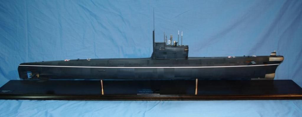
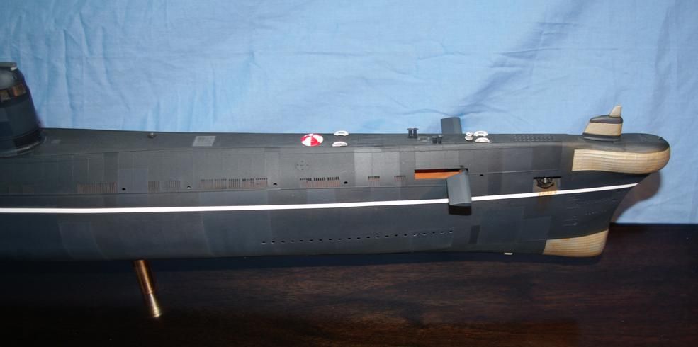
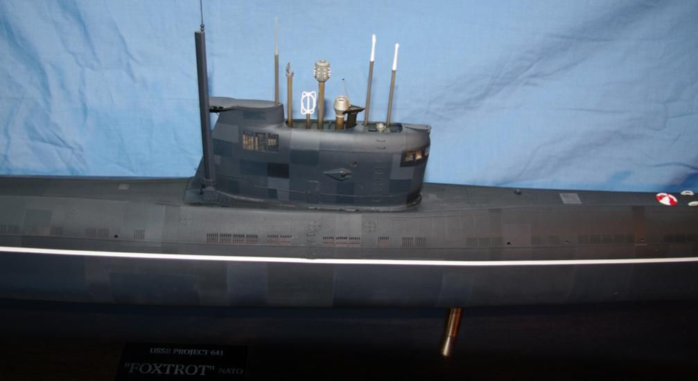
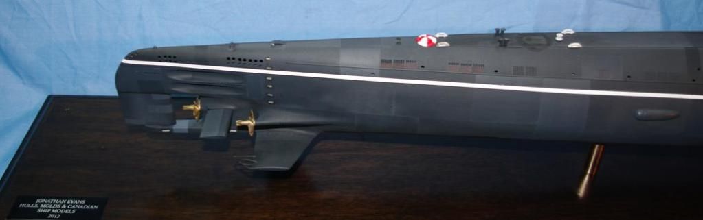
This project had its shares of ups & downs over the past couple years but thought that those who've been following this project since its inception might be interested in the final product of Rick Palumbo & David Meriman's excellent 1:72 Foxtrot kit. This is a static model commission completed by Jon Evans. More information on the build can be found at:
http://forum.sub-driver.com/showthread.php?2120-The-1-72-Foxtrot-by-Jon-Evans
Rick is selling the basic kit direct from his new site while David's fitting kit needs to be purchased separately from Sub-Driver.
http://www.scalemodelcastings.com/Model-kits-RC-and-static_c_1.html
http://www.sub-driver.com/fittings-kits.html
[img]http://i131.photobucket.com/albums/p292/herrmill/Modeling/FOXTROTFlags.jpg[/img]
[img]http://i131.photobucket.com/albums/p292/herrmill/Modeling/FOXTROT01.jpg[/img]
[img]http://i131.photobucket.com/albums/p292/herrmill/Modeling/FOXTROT01b.jpg[/img]
[img]http://i131.photobucket.com/albums/p292/herrmill/Modeling/FOXTROT01m.jpg[/img]
[img]http://i131.photobucket.com/albums/p292/herrmill/Modeling/FOXTROT01s.jpg[/img]
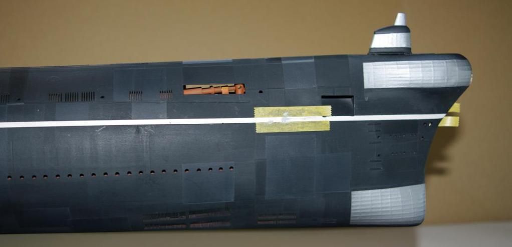
[img]http://i131.photobucket.com/albums/p292/herrmill/Modeling/Foxtrotpaintingbow.jpg[/img]
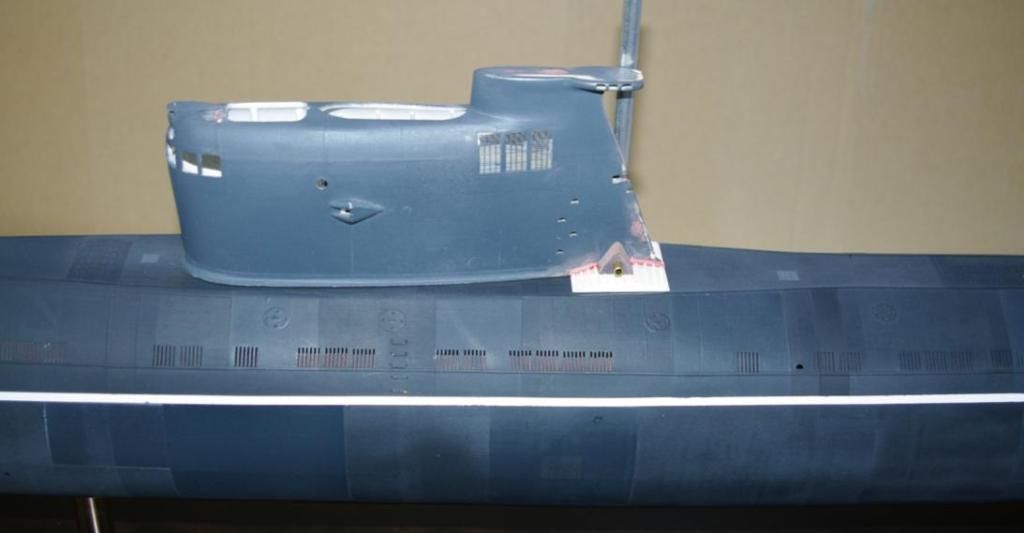
[img]http://i131.photobucket.com/albums/p292/herrmill/Modeling/Foxtrotpaintingconn.jpg[/img]
|
|
|
 |
Posted: Mon Oct 15, 2012 4:31 am |
|
|
 |
|
|
| |
Post subject: |
Re: Project 641 Foxtrot Kit |
|
|
Dear sir, I'm journalist and I write for the french magazine of radiocontroled model boats RC Marine. I'm interested to publich a repport of your Foxtrot russian submarine. Please contact me at the address : eric.bauthier@skynet.beBest regards. Eric Bauthier Dear sir,
I'm journalist and I write for the french magazine of radiocontroled model boats RC Marine. I'm interested to publich a repport of your Foxtrot russian submarine.
Please contact me at the address : eric.bauthier@skynet.be
Best regards.
Eric Bauthier
|
|
|
|
Posted: Wed Sep 21, 2011 2:33 am |
|
|
|
|
|
| |
Post subject: |
Re: Project 641 Foxtrot Kit |
|
|
Well guys, we're in the home stretch now & Project 641 "Foxtrot" is nearing completion. Rick's work on the mold is complete making this, without a doubt, one of the most detailed GRP hulls on the market & kit production has commenced this week, while David's back to finishing his prototype model. More details & photos can be seen at: http://forum.sub-driver.com/showthread.php?1462-Foxtrot-molds-now-ready-for-productionhttp://forum.sub-driver.com/showthread.php?1294-The-RPM-Foxtrot-by-David-Merriman
| Attachments: |
File comment: David's prototype got wet recently & is in the final detailing stage.

060.jpg [ 95.64 KiB | Viewed 3377 times ]
|
File comment: Rick's latest work on the hull shows an amazing level of detail.

P1010002.jpg [ 95.65 KiB | Viewed 3377 times ]
|
Well guys, we're in the home stretch now & Project 641 "Foxtrot" is nearing completion.
Rick's work on the mold is complete making this, without a doubt, one of the most detailed GRP hulls on the market & kit production has commenced this week, while David's back to finishing his prototype model.
More details & photos can be seen at:
[url]http://forum.sub-driver.com/showthread.php?1462-Foxtrot-molds-now-ready-for-production[/url]
[url]http://forum.sub-driver.com/showthread.php?1294-The-RPM-Foxtrot-by-David-Merriman[/url]
|
|
|
|
Posted: Wed May 11, 2011 6:43 pm |
|
|
|
|
|
| |
Post subject: |
Re: Project 641 Foxtrot Kit |
|
|
For those following this thread, the PE is finished & parts are being fabricated for the kit. Rick is currently modifying the hull to make it as upper/lower sections with flange split on the waterline. David Merriman is currently building the prototype hull & will be posting one of his entertaining Cabel Reports on Caswell's Sub-Driver forum in the coming weeks. In the meantime, you can see some of David's work on the Foxtrot in the new Sub-Driver Gazette that's available as a free PDF download via the link below: http://support.caswellplating.com/index.php?/Knowledgebase/List/Index/48/the-sub-driver-gazetteFor those following this thread, the PE is finished & parts are being fabricated for the kit. Rick is currently modifying the hull to make it as upper/lower sections with flange split on the waterline.
David Merriman is currently building the prototype hull & will be posting one of his entertaining Cabel Reports on Caswell's Sub-Driver forum in the coming weeks.
In the meantime, you can see some of David's work on the Foxtrot in the new Sub-Driver Gazette that's available as a free PDF download via the link below:
[url]http://support.caswellplating.com/index.php?/Knowledgebase/List/Index/48/the-sub-driver-gazette[/url]
|
|
|
|
Posted: Mon Mar 21, 2011 5:31 am |
|
|
|
|
|
| |
Post subject: |
Re: Project 641 Foxtrot Kit |
|
|
Yes, isn't it nice to see large scale submarines here on the forum but keep in mind this is a kit in the making thanks to RPM Tech Models & D&E Miniatures. For those interested in the Foxtrot, the kits will be offered by Caswell while the RTR versions will be available direct from RPM Tech. http://www.rpmtech1.comhttp://www.caswellplating.com/models/index.htmlIn the meantime, Rick is redoing his 1:32 Holland & other larger kits as well as his new 1:6 Neger & Marder. I'll start posting some photos of those shortly. Yes, isn't it nice to see large scale submarines here on the forum but keep in mind this is a kit in the making thanks to RPM Tech Models & D&E Miniatures. For those interested in the Foxtrot, the kits will be offered by Caswell while the RTR versions will be available direct from RPM Tech.
http://www.rpmtech1.com
http://www.caswellplating.com/models/index.html
In the meantime, Rick is redoing his 1:32 Holland & other larger kits as well as his new 1:6 Neger & Marder. I'll start posting some photos of those shortly.
|
|
|
|
Posted: Mon Feb 21, 2011 9:09 am |
|
|
|
|
|
| |
Post subject: |
Re: Project 641 Foxtrot Kit |
|
|
Hi Hermill fantastic job is good see a submarine model here.   Hi Hermill
fantastic job is good see a submarine model here. :thumbs_up_1: :wave_1:
|
|
|
|
Posted: Mon Feb 21, 2011 7:53 am |
|
|
|
|
|
| |
Post subject: |
Re: Project 641 Foxtrot Kit |
|
|
|
For those of you interested in the 1:72 torpedo launchers shown in the earlier update, you'll find detailed specifications & all the information you'll need in the Torpedo section over Caswell's Sub-Driver forum:
http://forum.sub-driver.com/forumdis...p?42-TORPEDOES
[img]http://i131.photobucket.com/albums/p292/herrmill/000_000_001_001_Wireless013.jpg[/img]
[img]http://i131.photobucket.com/albums/p292/herrmill/279.jpg[/img]
[img]http://i131.photobucket.com/albums/p292/herrmill/DSCN0144.jpg[/img]
[img]http://i131.photobucket.com/albums/p292/herrmill/DSCN0036.jpg[/img]
[img]http://i131.photobucket.com/albums/p292/herrmill/DSCN0138.jpg[/img]
[img]http://i131.photobucket.com/albums/p292/herrmill/046-1.jpg[/img]
[img]http://i131.photobucket.com/albums/p292/herrmill/050-1.jpg[/img]
[img]http://i131.photobucket.com/albums/p292/herrmill/034.jpg[/img]
[img]http://i131.photobucket.com/albums/p292/herrmill/059.jpg[/img]
[img]http://i131.photobucket.com/albums/p292/herrmill/030-1.jpg[/img]
[img]http://i131.photobucket.com/albums/p292/herrmill/040.jpg[/img]
|
|
|
|
Posted: Sun Feb 20, 2011 10:16 pm |
|
|
|
|
|
| |
Post subject: |
Re: Project 641 Foxtrot Kit - D&E SubDriver |
|
|
Here's David's cabel report along with photos of the new SubDriver for the Foxtrot.  Last week I spent my time developing a purpose built SubDriver (SD, some of you call them WTC's) for the Rick Palumbo 1/72 FOXTROT kit. This thing will be marketed through Caswell Inc., Rick's kit represents what I consider one of the most beautiful boats of the cold-war. The model is just the right size to crame in a full bridge and periscope-antenna array and deck items A detail freaks dream boat!. But, this beast will not be so big as to be a storage, display, and transportation burden. Two things drove the design of this SD: the anticipated weight and displacement of the models above waterline structure. And the need to keep the SD as short as possible in order to leave room for the inclusion of a six tube nest forward, and a four tube nest aft. I was able to achieve those requirements through use of a 2.5" Lexan cylinder -- big enough to accommodate a lot of gear in a short package, but presenting a cylinder small enough in diameter to keep the entire unit in the wet with the boat bobbing along in surfaced trim.  Atop is a completely outfitted, operational 2.5 FOXTROT SD. Below is a broken down FOXTROT SD, showing off the bulkheads, mounting hardware, seals, and fittings that goes into the manufacture of this SubDriver. As is my practice, the SD is divided internally into three spaces: The forward dry space, relatively short, houses the mission switch and high-capacity Lithium-polymer battery; the middle space, forming the ballast tank, containing the emergency 'come-home' propellant gas bottle, conduit tube (that passes the power cable from the forward dry space to the after dry space), blow valve, and vent valve; and, finally, the after dry space where the propulsion and control devices are. A unique feature of the FOXTROT SD is the use of three 180 size, 7-volt, direct-drive motors, all mounted to the motor bulkhead. The FOXTROT, like some of her sisters, featured three main shafts! The starboard propellers is right-hand pitch (clockwise rotation, looking forward), the center propeller (behind the single rudder) is righ-hand pitch. And the port propeller is left-hand pitch. Go figure?!... ... Russian's! Other than the three-motors, the FOXTROT SD is pretty much a standard layout.  Neither Rick nor I have put an evaluation FOXTROT hull in the water for trials, so right now it's a guess as to how effective differential operation of the port and starboard screws will be in turning the boat. My fear is that without differential use of the propellers, the FOXTROT model will turn as poorly as the German Type-21 the FOXTROT was based on! Further, if the two outboard shafts are toed in, like the Type-21, then the yawing force will be opposite to that which is normal, or there won't be any appreciable yawing moment at all. So, to find out how effective differential throttle use will be on the boats turning rate, I produced an evailuation motor bulkhead that has all three motors in parallel (starboard motor turning clockwise, center motor turning clockwise, and the port motor turning counterclockwise -- these motors will be driven through one common ESC. This is the baseline arrangement. I get this one. A second evaluation bulkhead has the starboard and center motors wired together in parallel, and the port motor wired alone. Two ESC's will permit differential use of the starboard (along with the center shaft) and port shafts -- we'll see if differential use of the propellers will effect useful yawing forces. Rick gets that one. The running gear is simple: big motors, directly coupled to the propellers through universal joints. The German's taught me this about matching DC motors to propellers: "Keep the can size of the motor equal to or larger than the diameter of the propeller, and you can direct-drive things without fear of over-heating". Nobody does this game better than those German's. Nobody!  The three 180 sized motors took up so much area on the motor bulkhead that I was forced to employ threaded studs as stand-offs to support the aluminum device securing platforms and bulkheads. Here you see an early version of the bulkheads and platforms within a cylinder, and a motor bulkhead with the three studs installed just forward of that cylinder. Note that I glue three micro-sized servos side-by-side. These will later be secured with a single brass strap to the device platform. Took about two days of trial and error to get an arrangement of bulkheads, and platform to fit all the devices in a tight and coherent arrangement.  And here is a motor bulkhead with all devices installed, and operational. Thank goodness for the Sombra Labs 8-channel receiver! It's not only small, but so selective and noise immune that I can put it in what has to be the most terrible of RF environments: Pushed up close to three screaming propulsion motors (see the spark suppression capacitors on the ass-end of the cans?), and in very close proximity to servos, and other devices that squirt out RF noises of their own. Yet, when I turn on the transmitter and receiver, everything works with out so much as a solitary glitch! The guy who designed and markets that receiver should get a Noble Prize! In this shot the motor bulkhead is upside down. Aft is the Caswell-Merriman LPB/Snort ballast sub-system -- used to empty the ballast tank, Kevin McLeod's fantastic little ADF (angle-keeper and fail-safe) -- the new version is smaller and so adaptive that you can mount it in any orientation within the SD because it is programmed to sense the gravity line, regardless of the devices orientation within the model submarine. (Kevin also designed and markets the Lipo-guard, low voltage detector, needed to protect the Lithium-polymer battery from damage as it approaches the critical low-voltage state).  Next to the ADF is the bullet-proof little MTronic's ESC. Though small it has the capacity to keep current going to the nearly stalled motors without breaking into a sweat. At the after end of the after bulkhead you see the green circuit-board of Kevin McLeod's little LPB controller. The white wire making up to the forward face of the motor bulkhead is the receiver antenna. The lug it mounts too extends through the bulkhead to the wet face of the motor bulkhead where the external antenna makes up to it. The battery cable connects to the battery and switch after it passes through the conduit tube within the ballast tank. The cable makes up, in parallel, to the ESC, Lipo-Guard, and LPB motor controller. The ESC has a BEC that feeds the receiver bus, that powers up all the devices connected to the receiver.  Looking down on the top of the motor bulkhead The red thing is Kevin's Lipo-guard battery protection circuit, under it is the Sombra Labs 8-channel, synthetic crystal receiver -- the brains of the SD! Just behind the motors, and strapped to the aluminum platform, are the three mini servos that operate the stern planes, bow planes, and rudder. Pretty tight packaging, huh?!  The device mounting is pretty sophisticated! three motor bulkheads here and the aluminum bulkheads, platform, and brass strap that secures the devices in place tightly, but with good access for adjustment, repair, and or replacement. There is a method to the madness!  Use of production templates, holding fixtures, and jigs insures speed of manufacture and uniformity of part fit.  A snorkel induction tube atop the FOXTROT SD will run up into the after fairing atop the FOXTROTS sail. Induction air will be pulled from atop the sail as it broaching the surface. That air, pushed into the ballast tank by the LPB, empties it, pushing the boat to surfaced trim. The on-board bottle, with its charge of liquefied gas, is only used in emergency -- when, for whatever reason, the boat can not broach the sail. The emergency blow ballast sub-system is either actuated remotely, through the transmitter, or locally, through Kevin's missing pulse detector -- an element of the ADF device.  As tightly as I packaged things in the FOXTROT SD's after dry space, I still left a two inch space between the devices and the after ballast bulkhead. This space for 'future growth'. Who knows?!  My FOXTROT SD. Rick's goes out Tuesday! Here's David's cabel report along with photos of the new SubDriver for the Foxtrot.
[img]http://i131.photobucket.com/albums/p292/herrmill/001.jpg[/img]
Last week I spent my time developing a purpose built SubDriver (SD, some of you call them WTC's) for the Rick Palumbo 1/72 FOXTROT kit. This thing will be marketed through Caswell Inc., Rick's kit represents what I consider one of the most beautiful boats of the cold-war. The model is just the right size to crame in a full bridge and periscope-antenna array and deck items A detail freaks dream boat!. But, this beast will not be so big as to be a storage, display, and transportation burden.
Two things drove the design of this SD: the anticipated weight and displacement of the models above waterline structure. And the need to keep the SD as short as possible in order to leave room for the inclusion of a six tube nest forward, and a four tube nest aft. I was able to achieve those requirements through use of a 2.5" Lexan cylinder -- big enough to accommodate a lot of gear in a short package, but presenting a cylinder small enough in diameter to keep the entire unit in the wet with the boat bobbing along in surfaced trim.
[img]http://i131.photobucket.com/albums/p292/herrmill/002-2.jpg[/img]
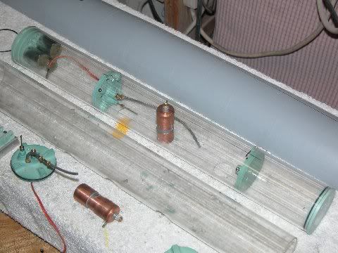
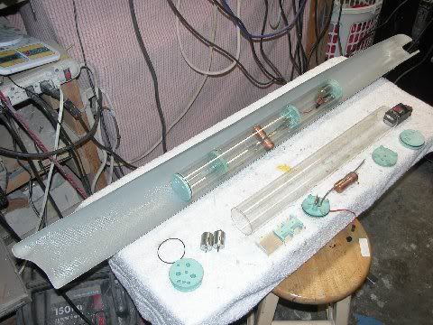
Atop is a completely outfitted, operational 2.5 FOXTROT SD. Below is a broken down FOXTROT SD, showing off the bulkheads, mounting hardware, seals, and fittings that goes into the manufacture of this SubDriver.
As is my practice, the SD is divided internally into three spaces: The forward dry space, relatively short, houses the mission switch and high-capacity Lithium-polymer battery; the middle space, forming the ballast tank, containing the emergency 'come-home' propellant gas bottle, conduit tube (that passes the power cable from the forward dry space to the after dry space), blow valve, and vent valve; and, finally, the after dry space where the propulsion and control devices are.
A unique feature of the FOXTROT SD is the use of three 180 size, 7-volt, direct-drive motors, all mounted to the motor bulkhead. The FOXTROT, like some of her sisters, featured three main shafts! The starboard propellers is right-hand pitch (clockwise rotation, looking forward), the center propeller (behind the single rudder) is righ-hand pitch. And the port propeller is left-hand pitch.
Go figure?!...
... Russian's!
Other than the three-motors, the FOXTROT SD is pretty much a standard layout.
[img]http://i131.photobucket.com/albums/p292/herrmill/003-2.jpg[/img]
Neither Rick nor I have put an evaluation FOXTROT hull in the water for trials, so right now it's a guess as to how effective differential operation of the port and starboard screws will be in turning the boat. My fear is that without differential use of the propellers, the FOXTROT model will turn as poorly as the German Type-21 the FOXTROT was based on! Further, if the two outboard shafts are toed in, like the Type-21, then the yawing force will be opposite to that which is normal, or there won't be any appreciable yawing moment at all.
So, to find out how effective differential throttle use will be on the boats turning rate, I produced an evailuation motor bulkhead that has all three motors in parallel (starboard motor turning clockwise, center motor turning clockwise, and the port motor turning counterclockwise -- these motors will be driven through one common ESC. This is the baseline arrangement. I get this one.
A second evaluation bulkhead has the starboard and center motors wired together in parallel, and the port motor wired alone. Two ESC's will permit differential use of the starboard (along with the center shaft) and port shafts -- we'll see if differential use of the propellers will effect useful yawing forces. Rick gets that one.
The running gear is simple: big motors, directly coupled to the propellers through universal joints. The German's taught me this about matching DC motors to propellers: "Keep the can size of the motor equal to or larger than the diameter of the propeller, and you can direct-drive things without fear of over-heating".
Nobody does this game better than those German's. Nobody!
[img]http://i131.photobucket.com/albums/p292/herrmill/004-2.jpg[/img]
The three 180 sized motors took up so much area on the motor bulkhead that I was forced to employ threaded studs as stand-offs to support the aluminum device securing platforms and bulkheads. Here you see an early version of the bulkheads and platforms within a cylinder, and a motor bulkhead with the three studs installed just forward of that cylinder.
Note that I glue three micro-sized servos side-by-side. These will later be secured with a single brass strap to the device platform. Took about two days of trial and error to get an arrangement of bulkheads, and platform to fit all the devices in a tight and coherent arrangement.
[img]http://i131.photobucket.com/albums/p292/herrmill/006-1.jpg[/img]
And here is a motor bulkhead with all devices installed, and operational. Thank goodness for the Sombra Labs 8-channel receiver! It's not only small, but so selective and noise immune that I can put it in what has to be the most terrible of RF environments: Pushed up close to three screaming propulsion motors (see the spark suppression capacitors on the ass-end of the cans?), and in very close proximity to servos, and other devices that squirt out RF noises of their own. Yet, when I turn on the transmitter and receiver, everything works with out so much as a solitary glitch!
The guy who designed and markets that receiver should get a Noble Prize!
In this shot the motor bulkhead is upside down. Aft is the Caswell-Merriman LPB/Snort ballast sub-system -- used to empty the ballast tank, Kevin McLeod's fantastic little ADF (angle-keeper and fail-safe) -- the new version is smaller and so adaptive that you can mount it in any orientation within the SD because it is programmed to sense the gravity line, regardless of the devices orientation within the model submarine.
(Kevin also designed and markets the Lipo-guard, low voltage detector, needed to protect the Lithium-polymer battery from damage as it approaches the critical low-voltage state).
[img]http://i131.photobucket.com/albums/p292/herrmill/007.jpg[/img]
Next to the ADF is the bullet-proof little MTronic's ESC. Though small it has the capacity to keep current going to the nearly stalled motors without breaking into a sweat.
At the after end of the after bulkhead you see the green circuit-board of Kevin McLeod's little LPB controller.
The white wire making up to the forward face of the motor bulkhead is the receiver antenna. The lug it mounts too extends through the bulkhead to the wet face of the motor bulkhead where the external antenna makes up to it.
The battery cable connects to the battery and switch after it passes through the conduit tube within the ballast tank. The cable makes up, in parallel, to the ESC, Lipo-Guard, and LPB motor controller. The ESC has a BEC that feeds the receiver bus, that powers up all the devices connected to the receiver.
[img]http://i131.photobucket.com/albums/p292/herrmill/008.jpg[/img]
Looking down on the top of the motor bulkhead The red thing is Kevin's Lipo-guard battery protection circuit, under it is the Sombra Labs 8-channel, synthetic crystal receiver -- the brains of the SD! Just behind the motors, and strapped to the aluminum platform, are the three mini servos that operate the stern planes, bow planes, and rudder.
Pretty tight packaging, huh?!
[img]http://i131.photobucket.com/albums/p292/herrmill/022-2.jpg[/img]
The device mounting is pretty sophisticated! three motor bulkheads here and the aluminum bulkheads, platform, and brass strap that secures the devices in place tightly, but with good access for adjustment, repair, and or replacement. There is a method to the madness!
[img]http://i131.photobucket.com/albums/p292/herrmill/036-1.jpg[/img]
Use of production templates, holding fixtures, and jigs insures speed of manufacture and uniformity of part fit.
[img]http://i131.photobucket.com/albums/p292/herrmill/049.jpg[/img]
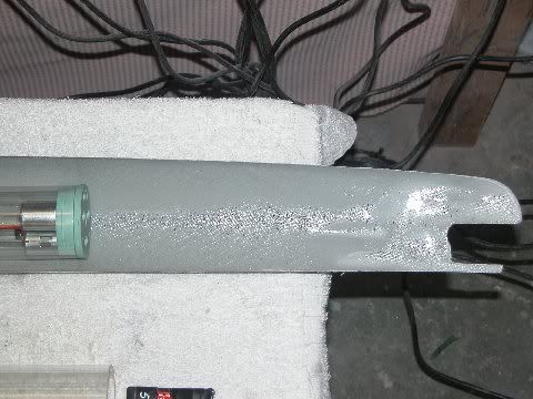
A snorkel induction tube atop the FOXTROT SD will run up into the after fairing atop the FOXTROTS sail. Induction air will be pulled from atop the sail as it broaching the surface. That air, pushed into the ballast tank by the LPB, empties it, pushing the boat to surfaced trim. The on-board bottle, with its charge of liquefied gas, is only used in emergency -- when, for whatever reason, the boat can not broach the sail. The emergency blow ballast sub-system is either actuated remotely, through the transmitter, or locally, through Kevin's missing pulse detector -- an element of the ADF device.
[img]http://i131.photobucket.com/albums/p292/herrmill/053.jpg[/img]
As tightly as I packaged things in the FOXTROT SD's after dry space, I still left a two inch space between the devices and the after ballast bulkhead. This space for 'future growth'. Who knows?!
[img]http://i131.photobucket.com/albums/p292/herrmill/056-1.jpg[/img]
My FOXTROT SD. Rick's goes out Tuesday!
|
|
|
|
Posted: Sun Feb 20, 2011 10:14 pm |
|
|
|
|
|
| |
Post subject: |
Re: Project 641 Foxtrot Kit |
|
|
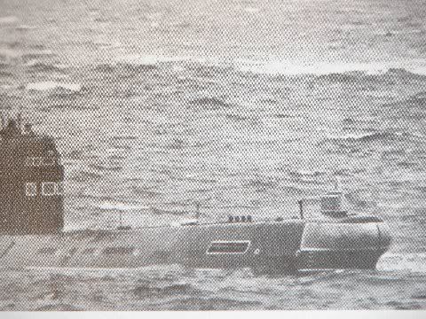
Jimmy, glad to hear you're enjoying the show. Our reference info & plans are primarily from several sources who've been interested in seeing this Foxtrot kit come about: Justin S. (ShadowPeo) & Gantu, both of whom can be found on the major RC sub forums. Gantu is one of the best sources anywhere when it comes to submarine reference material & can be contacted via his website: http://www.theplan-z.com. Jimmy, glad to hear you're enjoying the show. :thumbs_up_1:
Our reference info & plans are primarily from several sources who've been interested in seeing this Foxtrot kit come about: Justin S. (ShadowPeo) & Gantu, both of whom can be found on the major RC sub forums. Gantu is one of [i]the[/i] best sources anywhere when it comes to submarine reference material & can be contacted via his website: http://www.theplan-z.com.
|
|
|
|
Posted: Sun Feb 20, 2011 10:12 pm |
|
|
|
|
|
| |
Post subject: |
Re: Project 641 Foxtrot Kit |
|
|
Hi Herrmill, I'm following this fantastic work, watching very carefully. Do you know what kind of plans are being used in the project? Jimmy Hi Herrmill, I'm following this fantastic work, watching very carefully.
Do you know what kind of plans are being used in the project?
:thumbs_up_1: Jimmy
|
|
|
|
Posted: Sun Feb 20, 2011 2:09 pm |
|
|
|
|
|
| |
Post subject: |
Re: Project 641 Foxtrot Kit |
|
|
|
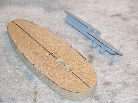
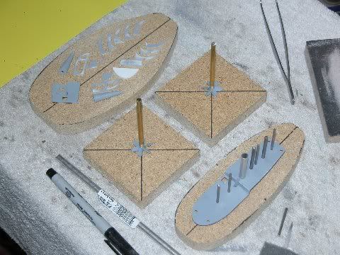
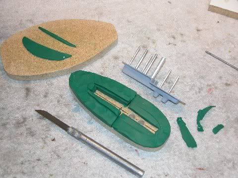
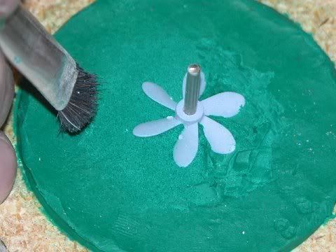
Here are some photos that David sent out today as he preps the hull for running gear & accessories.
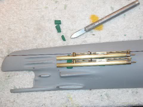
As requested by those who first proposed a kit, the hull will be split horizontally at the waterline to allow full access. As you can see, there will be plenty of room for running gear & torpedo launchers should you want to go all out with this beast.
David's prototype Sub-Driver™ for the Fox with its 3 direct drive motors which will include an ESC on the central shaft that will kick in at 75% power for full ahead & astern applications. Anything under that, the port & starboard shafts would be turning just like the real thing which will also go a long way towards conserving your battery power.
[img]http://i131.photobucket.com/albums/p292/herrmill/009.jpg[/img]
[img]http://i131.photobucket.com/albums/p292/herrmill/010.jpg[/img]
[img]http://i131.photobucket.com/albums/p292/herrmill/013.jpg[/img]
[img]http://i131.photobucket.com/albums/p292/herrmill/017.jpg[/img]
[img]http://i131.photobucket.com/albums/p292/herrmill/018.jpg[/img]
[img]http://i131.photobucket.com/albums/p292/herrmill/019-1.jpg[/img]
[img]http://i131.photobucket.com/albums/p292/herrmill/020-1.jpg[/img]
[img]http://i131.photobucket.com/albums/p292/herrmill/022-1.jpg[/img]
[img]http://i131.photobucket.com/albums/p292/herrmill/023.jpg[/img]
[img]http://i131.photobucket.com/albums/p292/herrmill/002-1.jpg[/img]
[img]http://i131.photobucket.com/albums/p292/herrmill/004-1.jpg[/img]
|
|
|
|
Posted: Tue Feb 15, 2011 8:02 pm |
|
|
|
|
|
| |
Post subject: |
Re: Project 641 Foxtrot Kit |
|
|
Here's a preview of the photo etch for decks & grating. 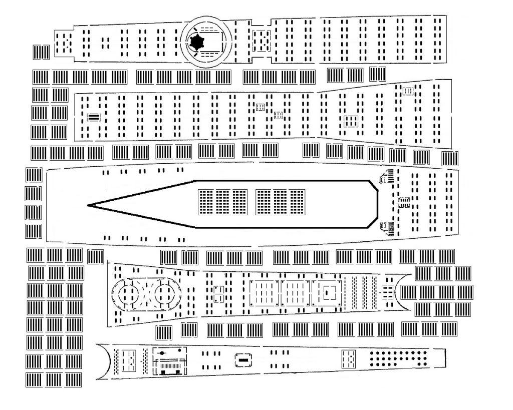 Here's a preview of the photo etch for decks & grating.
[img]http://i131.photobucket.com/albums/p292/herrmill/foxdeckpreview.jpg[/img]
|
|
|
|
Posted: Sun Feb 13, 2011 9:42 pm |
|
|
|
|
|
| |
Post subject: |
Re: Project 641 Foxtrot Kit - Mold Pour |
|
|
|
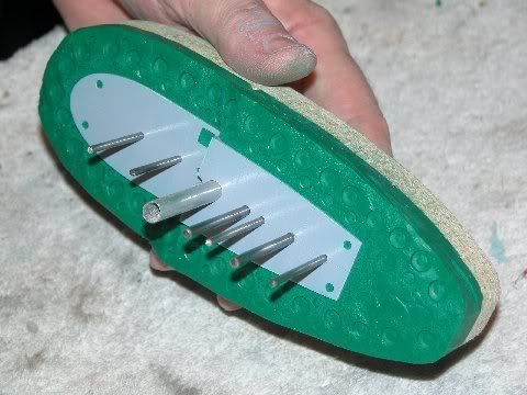
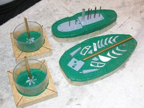
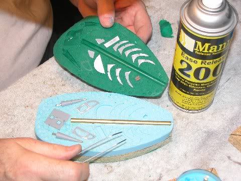
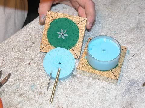
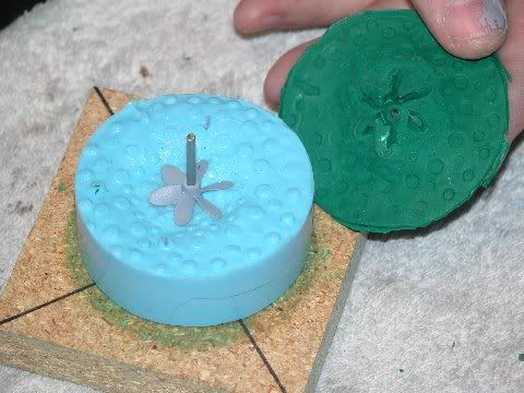
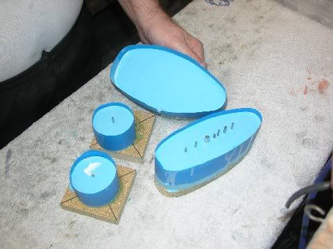
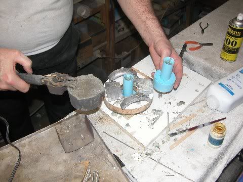
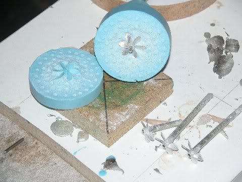
Rick has the tooling from David & is making molds. Here are some pics of the retracting scope work & molds for the Fox as well as the pending 1/6 Neger which will be released shortly.
[img]http://i131.photobucket.com/albums/p292/herrmill/Subs/P1010001-1.jpg[/img]
[img]http://i131.photobucket.com/albums/p292/herrmill/Subs/P1010002-1.jpg[/img]
[img]http://i131.photobucket.com/albums/p292/herrmill/Subs/P1010003-1.jpg[/img]
|
|
|
|
Posted: Tue Feb 01, 2011 8:54 pm |
|
|
|
|
|
| |
Post subject: |
Re: Project 641 Foxtrot Kit - Dive Planes & Pitch Mechanism |
|
|
|
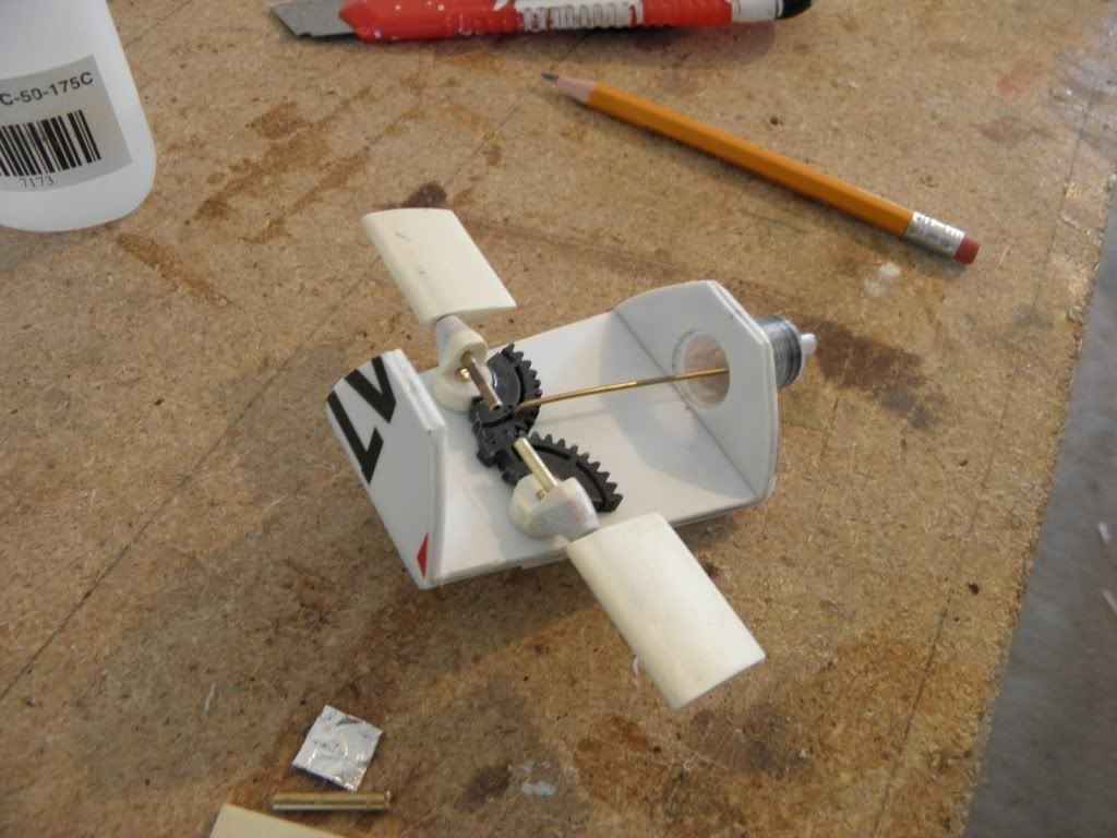
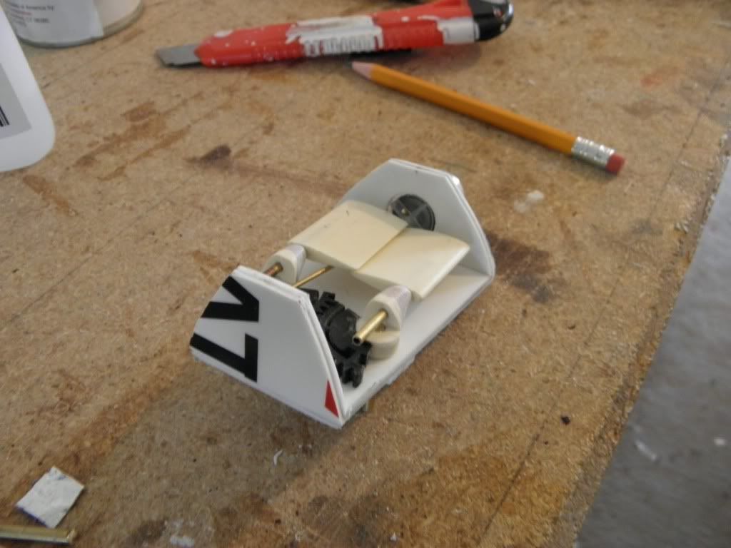
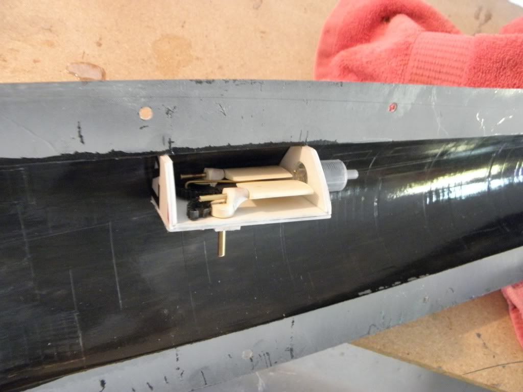
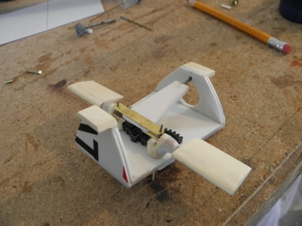
And here are a few that came in from Rick today of the prototype dive planes & pitch mechanism.
[img]http://i131.photobucket.com/albums/p292/herrmill/P1010001.jpg[/img]
[img]http://i131.photobucket.com/albums/p292/herrmill/P1010002.jpg[/img]
[img]http://i131.photobucket.com/albums/p292/herrmill/P1010003.jpg[/img]
[img]http://i131.photobucket.com/albums/p292/herrmill/P1010004.jpg[/img]
[img]http://i131.photobucket.com/albums/p292/herrmill/P1010006.jpg[/img]
|
|
|
|
Posted: Thu Jan 27, 2011 11:07 pm |
|
|
|
|
|
| |
Post subject: |
Re: Project 641 Foxtrot Kit - Test Shots |
|
|
|
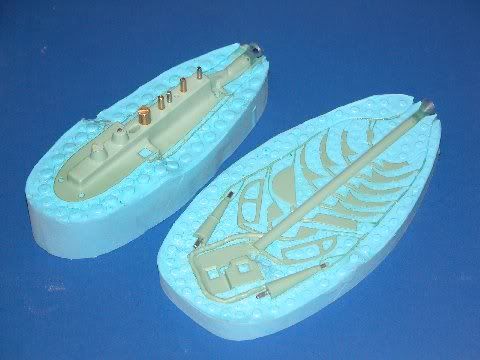
Here are the test shots from David's tooling for the upcoming kit. There's not much of a cabel report today, but plenty of photos to show what modeling craftsmanship looks like. :thumbs_up_1:
After seeing these, I fully understand why RPM Tech chose David to do the fitting package for the Fox. His attention to detail & accuracy is superb, & its no wonder that David has been doing fittings & other detailed parts like this for just about every US-based supplier of model submarines over the years.
[img]http://i131.photobucket.com/albums/p292/herrmill/006.jpg[/img]
[img]http://i131.photobucket.com/albums/p292/herrmill/011.jpg[/img]
[img]http://i131.photobucket.com/albums/p292/herrmill/012.jpg[/img]
[img]http://i131.photobucket.com/albums/p292/herrmill/014.jpg[/img]
[img]http://i131.photobucket.com/albums/p292/herrmill/015.jpg[/img]
[img]http://i131.photobucket.com/albums/p292/herrmill/016.jpg[/img]
[img]http://i131.photobucket.com/albums/p292/herrmill/019.jpg[/img]
[img]http://i131.photobucket.com/albums/p292/herrmill/020.jpg[/img]
[img]http://i131.photobucket.com/albums/p292/herrmill/021.jpg[/img]
[img]http://i131.photobucket.com/albums/p292/herrmill/022.jpg[/img]
[img]http://i131.photobucket.com/albums/p292/herrmill/025.jpg[/img]
[img]http://i131.photobucket.com/albums/p292/herrmill/026.jpg[/img]
[img]http://i131.photobucket.com/albums/p292/herrmill/029.jpg[/img]
[img]http://i131.photobucket.com/albums/p292/herrmill/030.jpg[/img]
[img]http://i131.photobucket.com/albums/p292/herrmill/032.jpg[/img]
[img]http://i131.photobucket.com/albums/p292/herrmill/035.jpg[/img]
[img]http://i131.photobucket.com/albums/p292/herrmill/035.jpg[/img]
[img]http://i131.photobucket.com/albums/p292/herrmill/036.jpg[/img]
[img]http://i131.photobucket.com/albums/p292/herrmill/038.jpg[/img]
[img]http://i131.photobucket.com/albums/p292/herrmill/039.jpg[/img]
[img]http://i131.photobucket.com/albums/p292/herrmill/047.jpg[/img]
[img]http://i131.photobucket.com/albums/p292/herrmill/050.jpg[/img]
[img]http://i131.photobucket.com/albums/p292/herrmill/054.jpg[/img]
[img]http://i131.photobucket.com/albums/p292/herrmill/056.jpg[/img]
[img]http://i131.photobucket.com/albums/p292/herrmill/058.jpg[/img]
[img]http://i131.photobucket.com/albums/p292/herrmill/060.jpg[/img]
[img]http://i131.photobucket.com/albums/p292/herrmill/061.jpg[/img]
[img]http://i131.photobucket.com/albums/p292/herrmill/062.jpg[/img]
|
|
|
|
Posted: Thu Jan 27, 2011 11:06 pm |
|
|
|
|
|
| |
Post subject: |
Re: Project 641 Foxtrot Kit SubDriver Prototype |
|
|
Here's David's latest installment as be begins work on a new SubDriver WTC designed specifically for the Fox. OK, guys, here's another look at the work I'm doing on the FOXTROT project. I have every confidence that you will have no problem following along, as I'm fond of observing to others: My readers are a pretty sharp group of guys, the cream of the crop, actually. I can't say that enough ... honestly!

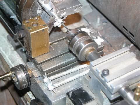
Desperate situations demand desperate measures! The damn Taig lathe belt broke last week and I can't do any heavy turning with it till the replacement belt arrives. I've been making do with rubber bands ... that's right, rubber-bands! ... but when the time came today to turn a RenShape master of the FOXTROT motor bulkhead, sized to fit a 2.5" Lexan cylinder, the Taig was simply not up to it.
So, I put the little drill press on its side, pressed a gel-cell battery into service as the foundation of a tool rest, chucked up a 1/4-20 machine-bolt used to hold the work, and spun a hunk of RenShape into shape. It isn't pretty, boys and girls, but it works!

OSHA standards?! ... we don't need no stinking OSHA standard!

Using the shop drawing I prepared of the FOXTROT SubDriver motor bulkhead to guide me as I took the work to the critical diameters.

Turning work on the drill press... err ... lath requires the insertion of a good firm mandrel through the work -- that was accomplished by drilling a hole through the center of a RenShape blank hacked out on the band saw, taping the hole for a 1/4-20 bolt, inserting the bolt, and making things fast at each end so the mandrel can't rotate within the work. Then its a simple matter to spin the work and do your worst.
This is a close-up of the shop drawing of the proposed FOXTROT motor bulkhead. The trick was to come up with a three-motor arrangement. It turned out that a motor bulkhead sized to fit a 2.5" cylinder would be big enough to accommodate three 280 sized motors. And the good news was that these motors -- employing the German formula: you can direct-drive a propeller providing the propeller diameter does not exceed the motor can diameter significantly -- were only a tad smaller in diameter than the propeller each would spin. Simplicity at its finest!

Showing off the ass-end of Rick's magnificent hull -- this is the business end where the three propellers swing in the breeze. Above, you see some of the components that go into the WTC/SubDriver that will be developed specifically for Rick's FOXTROT. The one unique item, to what will in all other characteristics be a 'standard' 2.5" SubDriver, is the use of the three-motor motor bulkhead -- seen here in the form of a tooling master. Tonight the first half of that rubber tool is curing -- tomorrow morning will see creation of the second half of that tool, And by late afternoon I'll have some pre-production cast resin parts in hand.
Tomorrow night I'll have the first pre-production FOXTROT SubDriver in hand.

The SubDriver I'm producing is but one option for the eventual FOXTROT customer: Rick will produce his own WTC, featuring an ingenious floating-piston ballast sub-system and hoists for retractable masts.
Now, it's back to the Caswell work and a long promised re-visit of a RTR USS MIAMI, and some SKY-DIVER master making.
Busy, busy ...Here's David's latest installment as be begins work on a new SubDriver WTC designed specifically for the Fox.
[i]OK, guys, here's another look at the work I'm doing on the FOXTROT project. I have every confidence that you will have no problem following along, as I'm fond of observing to others: My readers are a pretty sharp group of guys, the cream of the crop, actually. I can't say that enough ... honestly!
[img]http://i131.photobucket.com/albums/p292/herrmill/Subs/005-1.jpg[/img]
Desperate situations demand desperate measures! The damn Taig lathe belt broke last week and I can't do any heavy turning with it till the replacement belt arrives. I've been making do with rubber bands ... that's right, rubber-bands! ... but when the time came today to turn a RenShape master of the FOXTROT motor bulkhead, sized to fit a 2.5" Lexan cylinder, the Taig was simply not up to it.
So, I put the little drill press on its side, pressed a gel-cell battery into service as the foundation of a tool rest, chucked up a 1/4-20 machine-bolt used to hold the work, and spun a hunk of RenShape into shape. It isn't pretty, boys and girls, but it works!
[img]http://i131.photobucket.com/albums/p292/herrmill/Subs/008-1.jpg[/img]
OSHA standards?! ... we don't need no stinking OSHA standard!
[img]http://i131.photobucket.com/albums/p292/herrmill/Subs/009.jpg[/img]
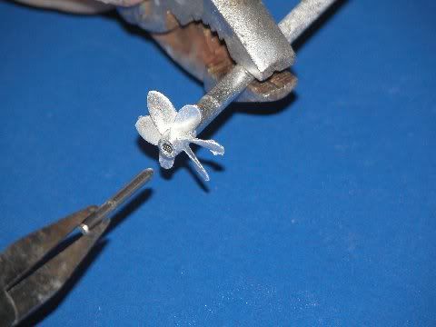
Using the shop drawing I prepared of the FOXTROT SubDriver motor bulkhead to guide me as I took the work to the critical diameters.
[img]http://i131.photobucket.com/albums/p292/herrmill/Subs/012-1.jpg[/img]
Turning work on the drill press... err ... lath requires the insertion of a good firm mandrel through the work -- that was accomplished by drilling a hole through the center of a RenShape blank hacked out on the band saw, taping the hole for a 1/4-20 bolt, inserting the bolt, and making things fast at each end so the mandrel can't rotate within the work. Then its a simple matter to spin the work and do your worst.
This is a close-up of the shop drawing of the proposed FOXTROT motor bulkhead. The trick was to come up with a three-motor arrangement. It turned out that a motor bulkhead sized to fit a 2.5" cylinder would be big enough to accommodate three 280 sized motors. And the good news was that these motors -- employing the German formula: you can direct-drive a propeller providing the propeller diameter does not exceed the motor can diameter significantly -- were only a tad smaller in diameter than the propeller each would spin. Simplicity at its finest!
[img]http://i131.photobucket.com/albums/p292/herrmill/Subs/015.jpg[/img]
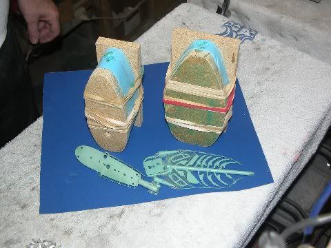
Showing off the ass-end of Rick's magnificent hull -- this is the business end where the three propellers swing in the breeze. Above, you see some of the components that go into the WTC/SubDriver that will be developed specifically for Rick's FOXTROT. The one unique item, to what will in all other characteristics be a 'standard' 2.5" SubDriver, is the use of the three-motor motor bulkhead -- seen here in the form of a tooling master. Tonight the first half of that rubber tool is curing -- tomorrow morning will see creation of the second half of that tool, And by late afternoon I'll have some pre-production cast resin parts in hand.
Tomorrow night I'll have the first pre-production FOXTROT SubDriver in hand.
[img]http://i131.photobucket.com/albums/p292/herrmill/Subs/020-1.jpg[/img]
The SubDriver I'm producing is but one option for the eventual FOXTROT customer: Rick will produce his own WTC, featuring an ingenious floating-piston ballast sub-system and hoists for retractable masts.
Now, it's back to the Caswell work and a long promised re-visit of a RTR USS MIAMI, and some SKY-DIVER master making.
Busy, busy ...[/i]
|
|
|
|
Posted: Tue Jan 04, 2011 11:40 pm |
|
|
|
|
|
| |
Post subject: |
Re: Project 641 Foxtrot Kit |
|
|
Thanks Dave. I'll be sure to pass that along to Rick & David who, in my humble opinion are some of the best commercial, ie, craftsmen, model makers around. They're getting some nice praise over on the German forums as well. I'm been cheerleading this project ever since one member over at SubPirates tried to get it started with Vladimir at Scale Ships. I can assure you with what we've been discussing, there will be many more projects down the road that will cater to the serious modelers with a level of detail should impress even the hard-core static fans. I'll be posting more photos of the Fox as they come in. Thanks Dave. I'll be sure to pass that along to Rick & David who, in my humble opinion are some of the best commercial, ie, craftsmen, model makers around. They're getting some nice praise over on the German forums as well. :thumbs_up_1:
I'm been cheerleading this project ever since one member over at SubPirates tried to get it started with Vladimir at Scale Ships. I can assure you with what we've been discussing, there will be many more projects down the road that will cater to the serious modelers with a level of detail should impress even the hard-core static fans.
I'll be posting more photos of the Fox as they come in.
|
|
|
|
Posted: Mon Jan 03, 2011 7:21 am |
|
|
|
|
|
| |
Post subject: |
Re: Project 641 Foxtrot Kit |
|
|
|
This shows some superb and ingenious building work . Thanks for posting
Dave Wooley
This shows some superb and ingenious building work . Thanks for posting
Dave Wooley
|
|
|
|
Posted: Mon Jan 03, 2011 7:05 am |
|
|
|
|
|
| |
Post subject: |
Re: Project 641 Foxtrot Kit |
|
|
And here are shots of Rick's prototype for retract mechanism for the bow planes based on what he's done earlier for Kilo. Fox retract is shown on the right of the Kilo's & in the second photo.   And here are shots of Rick's prototype for retract mechanism for the bow planes based on what he's done earlier for Kilo. Fox retract is shown on the right of the Kilo's & in the second photo.
[img]http://i131.photobucket.com/albums/p292/herrmill/Subs/P1010002.jpg[/img]
[img]http://i131.photobucket.com/albums/p292/herrmill/Subs/P1010003.jpg[/img]
|
|
|
|
Posted: Mon Jan 03, 2011 4:01 am |
|
|
|
|
|
| |
Post subject: |
Re: Project 641 Foxtrot Kit |
|
|
|
Some new pics from David of today's work on the bridge.
[img]http://i131.photobucket.com/albums/p292/herrmill/Subs/013.jpg[/img]
[img]http://i131.photobucket.com/albums/p292/herrmill/Subs/012.jpg[/img]
[img]http://i131.photobucket.com/albums/p292/herrmill/Subs/042.jpg[/img]
[img]http://i131.photobucket.com/albums/p292/herrmill/Subs/032.jpg[/img]
[img]http://i131.photobucket.com/albums/p292/herrmill/Subs/024.jpg[/img]
[img]http://i131.photobucket.com/albums/p292/herrmill/Subs/038.jpg[/img]
[img]http://i131.photobucket.com/albums/p292/herrmill/Subs/037.jpg[/img]
[img]http://i131.photobucket.com/albums/p292/herrmill/Subs/020.jpg[/img]
|
|
|
|
Posted: Mon Jan 03, 2011 4:00 am |
|
|
|
|