| Author |
Message |
|
|
| |
Post subject: |
Re: Model Monkey USS Lexington at Coral Sea Bridge Tower |
 |
|
|
After receiving the curved bulwarks for the LEX 1.1" mounts installed at PHNY from Steve, discussed above, I undertook to review the blueprint in Steve Wiper's WP #33 again just for grins. In the early days (a few years back before WP #33 was published) I saw the "pig pen" style of the bulwarks on several models and a conversion kit and agreed that shape made sense. All flat plates with no messy bending or cutting. Must be right. I now think the curved bulwarks are correct, so I'll state my case and let the splinters fly as they may. It's Sunday, and quiet. Why not? I should add that now that my thoughts have changed, it looks to me that the few photos available agree with me - as you'd suspect, you can start to see you are right when you think you are. Human nature.
Starting with the only hard evidence at hand (photos being softer evidence in this case because of distance or blurring), the drawing in Steve's book has lots of stuff that make it interesting. The drawing tells a story - it is not just a drawing a draftsman knocked out, and was checked and approved, end of story. In my training as an engineer, I've done quite a number of these, so it was fun to go back and reacquaint myself with something I'm glad I don't have to do any more.
The drawing in question is actually two drawings, that is, the first drawing was completed and submitted. Based on feedback from a Navy Bureau, changes were made resulting in the second drawing which Steve published. The first drawing was "Pearl Harbor Plan No. CV2-74/2-1" and titled "USS LEXINGTON (CV-2) General Arrangement New Anti-Aircraft Battery & Fire Control" with an original approval date 3-19-42. The three views of the 1.1" batteries and the curved bulwarks were not drawn on this plan as originally drawn. In the original version of the drawing, the 1.1"s forward of the bridge and aft of the stack / uptake group were arranged as pairs - one mount to port, the adjacent mount to starboard - with another pair forward of the first. In the case of the forward two pairs, all four of those mounts are placed on the deck (01 level) where the #2 8" turret had been removed - none of those four 1.1s was located ON the flight deck. A similar arrangement was implemented in the drawing behind the stack, with the exception that the aftmost pair of side by side mounts were to be located on the flight deck. Adjacent to each group of four 1.1" mounts, the plans also show tubs for pairs of directors for the 1.1s. Other work is called out on the plans, but I'll ignore it for this discussion.
However, change was in the wind. At least in the sections of the drawing relating to the installation of 1.1" mounts and fire control after the 8" turrets were removed. In three places above a previous drawing note describing the above discussed 1.1" mounts' and FC installation, a single line is added "Proposed to Bureau But Not Approved". Presumably this is BuAer "not Approving". Tracy has posted a message dated 17 April from the Navy Yard back to Chief Bureau of Ships which says the reason for the disapproval "was an unacceptable encroachment on the flight deck".
In any event, Plan A was out, and Plan B was proposed. Plan B is detailed in the drawing Steve published which is much the same drawing as before, but with some changes and detail drawings newly added. This drawing (from which those detail vignette drawings of the curved 1.1" bulwarks Steve posted above are extracted) is now called "Pearl Harbor Plan No. CV2-74/2-1, Alt. 1"
The 1.1" mounts are still shown in pairs, but each pair is now arranged fore and aft. The two pairs forward of the bridge are arranged with all four mounts in a single line. The end result of this inline arrangement is that now the forward pair is mounted on the flight deck, not at the 01 level as in the previous drawing. It should be noted that the pair of mounts located on the 01 level where the #2 8" mount was removed are offset to starboard as far as possible so that the mounts thensellves are not on the centerline of that platform. All splinter shields on all the mounts are located no further to port than the outer edge of the already existing stack and bridge structures. Each of these newly added vignette drawings has a short paragraph with some details and is preceded by "(Temporary)". In the vignette drawing of the aft 1.1" (Temporary) drawing the aftmost pair of mounts are arranged fore - aft and mounted on the flight deck. From the message dated 17 April referenced above, it appears the original plan was to have three 1.1" mounts located inline and on the flight deck, but there was insufficient time to remove the third 1.1" mount intended for this threesome from its current position forward of the stack and behind the bridge. When LEX sailed, there were three, not the planned four 1.1" mounts aft of the stack and I suggest the drawing represents the ship as completed when she sailed for Coral Sea.
There's more. See page 39 of WP#33 for the following part of the discussion. The upper right hand corner of the full drawing lists applicable references for the drawing, and they are numbered A - X, with each ref having a drawing number and title. Somewhat below that box is a smaller but similar box marker "Alterations". In between these two boxes is some Text titled "General Notes". And here is where the story becomes a bit clearer when taken in conjunction with Tracy's letter of 17 April 1942, a "Clipper Air Mail" letter from PHNY back to DC telling the Boss what was accomplished to LEX. (This letter was also published in Steve Wiper's earlier WP #11 "LEXINGTON Class Carriers".)
Going back to the original version of the drawing, and taking a closer look at each of the blocks of handwritten text under the "Proposed to Bureau But Not Approved", the very last words in each block of text is "See Ref 'V'" From the list of references, Ref V is P.H.No. CV2-74/2-8 New Proposed Location of 1.1" Guns & Dir Gen'l Arrgmt 'C' - a drawing attached to the Clipper letter of 17 April as Enclosure (B). While that drawing is not any that I've seen, it seems to be a modification of the original drawing we are discussing here before the "Temporary" Plan B was added and (I say) implemented before LEX sailed. Paragraph 4 of the 17 April letter seems to be devoted to convincing the Bureau that the original proposal with port and starboard pairs should not have been disapproved, and should be implemented when the ship is next available. Part of that paragraph: "The Commanding Officer has stated, and this opinion is concurred with by the Yard, that the arrangement shown on Enclosure (B) is much more preferable than an "in line" arrangement, and offers much less restriction to flight operations." There is a reasonable point here since none of the 1.1" tubs would have been on the flight deck forward of the bridge, and only a single pair aft of the stack would be on the flight deck, but offset to starboard and actually partially overhanging the side of the hull.
Applying the same scrutiny to the handwritten blocks of text under the heading "Temporary 1.1" Gun Installation - Ford. / - Aft.", the very last words in each block are "See Ref G". Ref G is titled "P.H.No. CV2 - 74/2-3 Temp Inst'l'n of 7-1.1 A.A.M. Guns". The 7 is not aligned with the other text, almost as though an 8 was erased and a 7 put in its place. Yeah, I know some will roll there eyes on that one.
Finally to the General Notes section. There is a triangular flag labelled Alt 1. with two arrows drawn from it. The first arrow points to this text: 1 - Work to be installed at a later date includes references U, V, T, W, X. The second arrow points to: 2. Work now installed includes references L,I,G,A,B,D,E,F,C,H,M,Q,P,R,O,S.
In the Alterations block, next to Alt 1. it states "Added General Notes # 1. & 2." followed by two sets of initials and dated 4/15/42.
While I certainly believe there are times when blueprints are not necessarily indicative of work actually completed, in this case I do believe these blueprint drawings show work actually completed on LEX. The dated drawings would seem to be documents showing what had already been accomplished rather than the proposed work. I'm even betting that the number 7 was changed from an 8 in ref g. indicating the lack of time to complete the installation of all 8 for reasons described in para 3 of the 17 April Clipper letter. OBTW, I suspect LEX was out of the PHNY by 15 April, if so these drawings and correspondence represent after the fact documentation vice proposed or as yet uncompleted work.
By extension, this line of reasoning supports, in my view, the shape of the 1.1" splinter shields / bulwarks as being curved at the fore or aft ends as the subject drawing shows.
I always like to say that a picture saves a thousand words. This one didn't.
After receiving the curved bulwarks for the LEX 1.1" mounts installed at PHNY from Steve, discussed above, I undertook to review the blueprint in Steve Wiper's WP #33 again just for grins. In the early days (a few years back before WP #33 was published) I saw the "pig pen" style of the bulwarks on several models and a conversion kit and agreed that shape made sense. All flat plates with no messy bending or cutting. Must be right. I now think the curved bulwarks are correct, so I'll state my case and let the splinters fly as they may. It's Sunday, and quiet. Why not? I should add that now that my thoughts have changed, it looks to me that the few photos available agree with me - as you'd suspect, you can start to see you are right when you think you are. Human nature.
Starting with the only hard evidence at hand (photos being softer evidence in this case because of distance or blurring), the drawing in Steve's book has lots of stuff that make it interesting. The drawing tells a story - it is not just a drawing a draftsman knocked out, and was checked and approved, end of story. In my training as an engineer, I've done quite a number of these, so it was fun to go back and reacquaint myself with something I'm glad I don't have to do any more.
The drawing in question is actually two drawings, that is, the first drawing was completed and submitted. Based on feedback from a Navy Bureau, changes were made resulting in the second drawing which Steve published. The first drawing was "Pearl Harbor Plan No. CV2-74/2-1" and titled "USS LEXINGTON (CV-2) General Arrangement New Anti-Aircraft Battery & Fire Control" with an original approval date 3-19-42. The three views of the 1.1" batteries and the curved bulwarks were not drawn on this plan as originally drawn. In the original version of the drawing, the 1.1"s forward of the bridge and aft of the stack / uptake group were arranged as pairs - one mount to port, the adjacent mount to starboard - with another pair forward of the first. In the case of the forward two pairs, all four of those mounts are placed on the deck (01 level) where the #2 8" turret had been removed - [i]none [/i]of those four 1.1s was located ON the flight deck. A similar arrangement was implemented in the drawing behind the stack, with the exception that the aftmost pair of side by side mounts were to be located on the flight deck. Adjacent to each group of four 1.1" mounts, the plans also show tubs for pairs of directors for the 1.1s. Other work is called out on the plans, but I'll ignore it for this discussion.
However, change was in the wind. At least in the sections of the drawing relating to the installation of 1.1" mounts and fire control after the 8" turrets were removed. In three places above a previous drawing note describing the above discussed 1.1" mounts' and FC installation, a single line is added "Proposed to Bureau But Not Approved". Presumably this is BuAer "not Approving". Tracy has posted a message dated 17 April from the Navy Yard back to Chief Bureau of Ships which says the reason for the disapproval "was an unacceptable encroachment on the flight deck".
In any event, Plan A was out, and Plan B was proposed. Plan B is detailed in the drawing Steve published which is much the same drawing as before, but with some changes and detail drawings newly added. This drawing (from which those detail vignette drawings of the curved 1.1" bulwarks Steve posted above are extracted) is now called "Pearl Harbor Plan No. CV2-74/2-1, Alt. 1"
The 1.1" mounts are still shown in pairs, but each pair is now arranged fore and aft. The two pairs forward of the bridge are arranged with all four mounts in a single line. The end result of this inline arrangement is that now the forward pair is mounted on the flight deck, not at the 01 level as in the previous drawing. It should be noted that the pair of mounts located on the 01 level where the #2 8" mount was removed are offset to starboard as far as possible so that the mounts thensellves are not on the centerline of that platform. All splinter shields on all the mounts are located no further to port than the outer edge of the already existing stack and bridge structures. Each of these newly added vignette drawings has a short paragraph with some details and is preceded by "(Temporary)". In the vignette drawing of the aft 1.1" (Temporary) drawing the aftmost pair of mounts are arranged fore - aft and mounted on the flight deck. From the message dated 17 April referenced above, it appears the original plan was to have three 1.1" mounts located inline and on the flight deck, but there was insufficient time to remove the third 1.1" mount intended for this threesome from its current position forward of the stack and behind the bridge. When LEX sailed, there were three, not the planned four 1.1" mounts aft of the stack and I suggest the drawing represents the ship as completed when she sailed for Coral Sea.
There's more. See page 39 of WP#33 for the following part of the discussion. The upper right hand corner of the full drawing lists applicable references for the drawing, and they are numbered A - X, with each ref having a drawing number and title. Somewhat below that box is a smaller but similar box marker "Alterations". In between these two boxes is some Text titled "General Notes". And here is where the story becomes a bit clearer when taken in conjunction with Tracy's letter of 17 April 1942, a "Clipper Air Mail" letter from PHNY back to DC telling the Boss what was accomplished to LEX. (This letter was also published in Steve Wiper's earlier WP #11 "LEXINGTON Class Carriers".)
Going back to the original version of the drawing, and taking a closer look at each of the blocks of handwritten text under the "Proposed to Bureau But Not Approved", the very last words in each block of text is "See Ref 'V'" From the list of references, Ref V is P.H.No. CV2-74/2-8 New Proposed Location of 1.1" Guns & Dir Gen'l Arrgmt 'C' - a drawing attached to the Clipper letter of 17 April as Enclosure (B). While that drawing is not any that I've seen, it seems to be a modification of the original drawing we are discussing here before the "Temporary" Plan B was added and (I say) implemented before LEX sailed. Paragraph 4 of the 17 April letter seems to be devoted to convincing the Bureau that the original proposal with port and starboard pairs should not have been disapproved, and should be implemented when the ship is next available. Part of that paragraph: "The Commanding Officer has stated, and this opinion is concurred with by the Yard, that the arrangement shown on Enclosure (B) is much more preferable than an "in line" arrangement, and offers much less restriction to flight operations." There is a reasonable point here since none of the 1.1" tubs would have been on the flight deck forward of the bridge, and only a single pair aft of the stack would be on the flight deck, but offset to starboard and actually partially overhanging the side of the hull.
Applying the same scrutiny to the handwritten blocks of text under the heading "Temporary 1.1" Gun Installation - Ford. / - Aft.", the very last words in each block are "See Ref G". Ref G is titled "P.H.No. CV2 - 74/2-3 Temp Inst'l'n of 7-1.1 A.A.M. Guns". The 7 is not aligned with the other text, almost as though an 8 was erased and a 7 put in its place. Yeah, I know some will roll there eyes on that one.
Finally to the General Notes section. There is a triangular flag labelled Alt 1. with two arrows drawn from it. The first arrow points to this text: 1 - Work to be installed at a later date includes references U, [b][u]V[/u][/b], T, W, X. The second arrow points to: 2. Work now installed includes references L,I,[b][i][u]G[/u][/i][/b],A,B,D,E,F,C,H,M,Q,P,R,O,S.
In the Alterations block, next to Alt 1. it states "Added General Notes # 1. & 2." followed by two sets of initials and dated 4/15/42.
While I certainly believe there are times when blueprints are not necessarily indicative of work actually completed, in this case I do believe these blueprint drawings show work actually completed on LEX. The dated drawings would seem to be documents showing what had already been accomplished rather than the proposed work. I'm even betting that the number 7 was changed from an 8 in ref g. indicating the lack of time to complete the installation of all 8 for reasons described in para 3 of the 17 April Clipper letter. OBTW, I suspect LEX was out of the PHNY by 15 April, if so these drawings and correspondence represent after the fact documentation vice proposed or as yet uncompleted work.
By extension, this line of reasoning supports, in my view, the shape of the 1.1" splinter shields / bulwarks as being curved at the fore or aft ends as the subject drawing shows.
I always like to say that a picture [i]saves[/i] a thousand words. This one didn't.
|
|
|
 |
Posted: Sun Nov 15, 2015 1:20 pm |
|
|
 |
|
|
| |
Post subject: |
Re: Model Monkey USS Lexington at Coral Sea Bridge Tower |
|
|
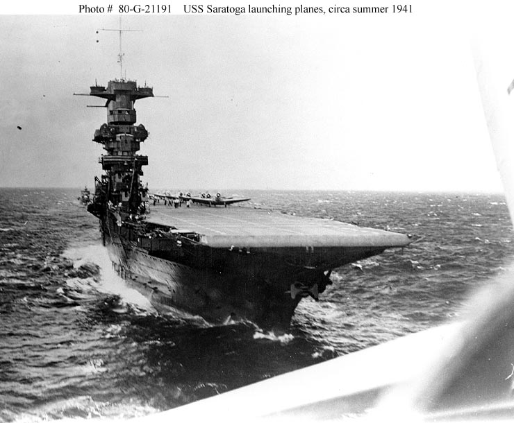
Aaaargh! I thought I had got away without buying a Trumpeter Lexington as I have the Saratoga and that is enough. Now this?  Aaaargh!
I thought I had got away without buying a Trumpeter Lexington as I have the Saratoga and that is enough. Now this?
:tongue:
|
|
|
|
Posted: Fri Nov 13, 2015 10:06 am |
|
|
|
|
|
| |
Post subject: |
Re: Model Monkey USS Lexington at Coral Sea Bridge Tower |
|
|
|
I have bought and received both the Coral Sea island structure and the curved splinter shields / bulwarks for the 1.1"s. I am very impressed, something to which I am not automatically inclined generally. I think Steve has done a great job here. There is a problem, of course. A few years back I put the LEX aside while the final configuration debate continued. I took my best shot at scratching the structure, and it turned out to be pretty well right with what is more or less agreed at this point. But now I have these other projects already in work . . . ..
When I get a chance, I will paint the #D printed parts and take some pix if someone else doesn't do it first. First I'll have to buy some acrylic 5N then learn how to shoot it. Sigh. This is never easy. Still, This is a really good looking product - hopefully there are enough folks currently working on a 1942 LEX to benefit from it (and for Steve to benefit).
Dick, or anyone else - are there any photos of the 5" director top above the forward island structure - something that shows the Mk 19 and the circular shields that look like 20MM tubs? I'm also a bit fuzzy on the center section of the top where the second half of both Mk 19s reside on some sort of platform. I have Stern's book, Wiper's two LEX class books, a Polish book, and a SARA book by Fry. I saw only one photo of the outboard section of the Mk 19 with three crewmen in attendance in Stern's book, and the director was surrounded by three bar railing, not plating. I realize it would take some doing to get a photo of that area, but I thought maybe I might be overlooking something obvious.
I assume, without any likelihood that I'm wrong, that no one makes any Mk 19 directors in 1/350th.
|
|
|
|
Posted: Tue Nov 10, 2015 10:28 pm |
|
|
|
|
|
| |
Post subject: |
Re: Model Monkey USS Lexington at Coral Sea Bridge Tower |
|
|
|
I just bought the set in 1/350th. Nice job!
I just bought the set in 1/350th. Nice job!
|
|
|
|
Posted: Sun Nov 08, 2015 5:33 pm |
|
|
|
|
|
| |
Post subject: |
Re: Model Monkey USS Lexington at Coral Sea Bridge Tower |
|
|
Dick J wrote: I would like to make a couple of points while you are still early in the project. Thanks! Your opinions and help are very valued! Dick J wrote: First, the MK-19 directors had two parts. The main director portion was on a circular raised platform as seen in this shot of Northampton. http://www.navsource.org/archives/04/026/0402626.jpg Note that in this picture that the rangefinders are still absent from the semicircular projections of the deck that supports the raised platforms for the main part of the director. Similarly, on the Lexington's, the main portion of the director was on a raised circular platform. Two were in the center of the upper fore top. The rangefinders were in the lower outboard positions. Agreed. From the perspective of the 3D model's design, as a general principle, there are some features of a 3D printed model that would be more realistically replicated by other materials. The Lexington and Saratoga bridge towers (because of the separate funnel, not sure that "island" is the more correct term for CV-2 class), are intended to provide the modeler with a good superstructure from which to add details that would not be 3D printable by Shapeways or look more to scale if made in another medium, PE or thin styrene, for example. While the cylindrical Mk.19 Director bases are certainly 3D printable, and their dimensions are generally known, the platform itself is too thin to print realistically. Therefore, I decided to omit the base and platform from the design leaving just subtle locator disks to aid the modeler. Having said that, the directors and their platforms are obviously important features of the ship and your comments are very helpful in informing the modeler what needs to be added and where it goes, and are most appreciated. Dick J wrote: When the extension was added to the front of the upper top, it was at the level of the raised director platforms for the MK-19's. Saratoga had a similar extension after her 1941 refit, before it was all removed in 1942. Agreed. This is a feature that I very much wanted to include and look right. While the height of the extension can be determined, documentation and photos of the shape, extents, dimensions and aft configuration in 2D form are absent. The absence of good 2D documentation was a struggle in developing an acceptable 3D design. Hopefully, better documentation will come forth. If it does, I will adjust the design. Dick J wrote: On the deck level for 8" gun turrets 2 and 3, the access to the turret was on the sides. Since the turrets were the width of the deckhouse, the deck was extended out on either side of the turrets. The outer corners were rounded except for the forward end of the extension to starboard of turret 2, which was beveled. This is a feature captured in the 3D design. Dick J wrote: The deck did not extend forward of the deckhouse for turret 2 nor aft of the deckhouse for turret 3. There was no need there, and it would have interfered with turrets 1 and 4. Did they extend those decks to support the end bulwarks of the splinter screens? The photos are unclear on that point. So extending the decks fore and aft is an assumption on your part. (Not totally beyond reason, but not actually mentioned in the documentation.) Respectfully disagree. While the 1936 & 1941 Booklets of General Plans for Lexington are drawn with no fore-aft extension, the 1944 Booklet of General Plans for Saratoga does show a measureable extension, as do numerous photos of both ships throughout their lives. The photos confirm Sara's drawings as essentially correct and show that Lex's drawings are incorrect as built. Therefore, I have discounted Lex's drawings of this feature in favor of Sara's drawings and the numerous Lexington and Saratoga photos of these fore-aft extensions. Lex: see Wiper's Warship Pictorial 33 USS Lexington CV-2, pages 11, 13, 14, 24, 30, and 31. Sara: see Doyle's USS Saratoga Squadron at Sea, pages 47, 49, 50, 54, 73, 77, 89, 103, 104, 111, 116, 131, 134, 135, 141, 151, and 156. Dick J wrote: Also, while the Lexington's staff requested that the flag level be enclosed with the bullet resistant glass, it is not clear if there was either the time or the materials on hand to do so. The last photo before she was sunk is all we have to go on, and what it really shows has been much debated. Just because the protected enclosure was requested doesn't mean the entire request was fulfilled. For all that we do know about her, there is still a lot that we still don't. Agreed. Obviously, the 3D design has no clear features, but the openings are present. As discussed earlier in the thread, the shape and extents of the enclosure and window openings as 3D designed are the best approximation that can be made from the available, limited photographic and documentary evidence we now have. The available evidence was very carefully considered in the design. Dimensions of the enclosure and window openings were either extrapolated or interpolated from known dimensions. New features were logically oriented and joined to known, existing features (enclosure facets match and meet splinter shield facets, for example). In the absence of good facts, assumptions were made in order to complete a reasonable design. One of the beauties of 3D design is that should further evidence come forth, the designs can be adjusted to match new evidence. It is now up to the modeler to determine if the Model Monkey design is more reasonably accurate than Trumpeter's and Fujimi's. [quote="Dick J"]I would like to make a couple of points while you are still early in the project.[/quote]
Thanks! Your opinions and help are very valued!
[quote="Dick J"]First, the MK-19 directors had two parts. The main director portion was on a circular raised platform as seen in this shot of Northampton. http://www.navsource.org/archives/04/026/0402626.jpg Note that in this picture that the rangefinders are still absent from the semicircular projections of the deck that supports the raised platforms for the main part of the director. Similarly, on the Lexington's, the main portion of the director was on a raised circular platform. Two were in the center of the upper fore top. The rangefinders were in the lower outboard positions.[/quote]
Agreed. From the perspective of the 3D model's design, as a general principle, there are some features of a 3D printed model that would be more realistically replicated by other materials. The [i]Lexington[/i] and [i]Saratoga[/i] bridge towers (because of the separate funnel, not sure that "island" is the more correct term for CV-2 class), are intended to provide the modeler with a good superstructure from which to add details that would not be 3D printable by Shapeways or look more to scale if made in another medium, PE or thin styrene, for example. While the cylindrical Mk.19 Director bases are certainly 3D printable, and their dimensions are generally known, the platform itself is too thin to print realistically. Therefore, I decided to omit the base and platform from the design leaving just subtle locator disks to aid the modeler. Having said that, the directors and their platforms are obviously important features of the ship and your comments are very helpful in informing the modeler what needs to be added and where it goes, and are most appreciated.
[quote="Dick J"]When the extension was added to the front of the upper top, it was at the level of the raised director platforms for the MK-19's. Saratoga had a similar extension after her 1941 refit, before it was all removed in 1942.[/quote]
Agreed. This is a feature that I very much wanted to include and look right. While the height of the extension can be determined, documentation and photos of the shape, extents, dimensions and aft configuration in 2D form are absent. The absence of good 2D documentation was a struggle in developing an acceptable 3D design. Hopefully, better documentation will come forth. If it does, I will adjust the design.
[quote="Dick J"]On the deck level for 8" gun turrets 2 and 3, the access to the turret was on the sides. Since the turrets were the width of the deckhouse, the deck was extended out on either side of the turrets. The outer corners were rounded except for the forward end of the extension to starboard of turret 2, which was beveled. [/quote]
This is a feature captured in the 3D design.
[quote="Dick J"]The deck did not extend forward of the deckhouse for turret 2 nor aft of the deckhouse for turret 3. There was no need there, and it would have interfered with turrets 1 and 4. Did they extend those decks to support the end bulwarks of the splinter screens? The photos are unclear on that point. So extending the decks fore and aft is an assumption on your part. (Not totally beyond reason, but not actually mentioned in the documentation.)[/quote]
Respectfully disagree. While the 1936 & 1941 Booklets of General Plans for [i]Lexington[/i] are drawn with no fore-aft extension, the 1944 Booklet of General Plans for [i]Saratoga[/i] does show a measureable extension, as do numerous photos of both ships throughout their lives. The photos confirm [i]Sara[/i]'s drawings as essentially correct and show that Lex's drawings are incorrect as built. Therefore, I have discounted[i] Lex[/i]'s drawings of this feature in favor of [i]Sara[/i]'s drawings and the numerous [i]Lexington[/i] and [i]Saratoga[/i] photos of these fore-aft extensions.
[i]Lex[/i]: see Wiper's Warship Pictorial 33 [i]USS Lexington CV-2[/i], pages 11, 13, 14, 24, 30, and 31.
[i]Sara[/i]: see Doyle's [i]USS Saratoga Squadron at Sea[/i], pages 47, 49, 50, 54, 73, 77, 89, 103, 104, 111, 116, 131, 134, 135, 141, 151, and 156.
[quote="Dick J"]Also, while the Lexington's staff requested that the flag level be enclosed with the bullet resistant glass, it is not clear if there was either the time or the materials on hand to do so. The last photo before she was sunk is all we have to go on, and what it really shows has been much debated. Just because the protected enclosure was requested doesn't mean the entire request was fulfilled. For all that we do know about her, there is still a lot that we still don't.[/quote]
Agreed. Obviously, the 3D design has no clear features, but the openings are present. As discussed earlier in the thread, the shape and extents of the enclosure and window openings as 3D designed are the best approximation that can be made from the available, limited photographic and documentary evidence we now have. The available evidence was very carefully considered in the design. Dimensions of the enclosure and window openings were either extrapolated or interpolated from known dimensions. New features were logically oriented and joined to known, existing features (enclosure facets match and meet splinter shield facets, for example). In the absence of good facts, assumptions were made in order to complete a reasonable design. One of the beauties of 3D design is that should further evidence come forth, the designs can be adjusted to match new evidence.
It is now up to the modeler to determine if the Model Monkey design is more reasonably accurate than Trumpeter's and Fujimi's.
|
|
|
|
Posted: Fri Nov 06, 2015 10:52 am |
|
|
|
|
|
| |
Post subject: |
Re: Model Monkey USS Lexington at Coral Sea Bridge Tower |
|
|
I would like to make a couple of points while you are still early in the project. First, the MK-19 directors had two parts. The main director portion was on a circular raised platform as seen in this shot of Northampton. http://www.navsource.org/archives/04/026/0402626.jpg Note that in this picture that the rangefinders are still absent from the semicircular projections of the deck that supports the raised platforms for the main part of the director. Similarly, on the Lexington's, the main portion of the director was on a raised circular platform. Two were in the center of the upper fore top. The rangefinders were in the lower outboard positions. Aft of the stack, the main directors were forward, closer to the stack (on their circular platforms) with the rangefinders slightly lower aft of them. So the Lexington's were built with 4 sets of MK-19 gear. When the extension was added to the front of the upper top, it was at the level of the raised director platforms for the MK-19's. Saratoga had a similar extension after her 1941 refit, before it was all removed in 1942. http://www.navsource.org/archives/02/020355.jpgOn the deck level for 8" gun turrets 2 and 3, the access to the turret was on the sides. Since the turrets were the width of the deckhouse, the deck was extended out on either side of the turrets. The outer corners were rounded except for the forward end of the extension to starboard of turret 2, which was beveled. The deck did not extend forward of the deckhouse for turret 2 nor aft of the deckhouse for turret 3. There was no need there, and it would have interfered with turrets 1 and 4. Did they extend those decks to support the end bulwarks of the splinter screens? The photos are unclear on that point. So extending the decks fore and aft is an assumption on your part. (Not totally beyond reason, but not actually mentioned in the documentation.) Also, while the Lexington's staff requested that the flag level be enclosed with the bullet resistant glass, it is not clear if there was either the time or the materials on hand to do so. The last photo before she was sunk is all we have to go on, and what it really shows has been much debated. Just because the protected enclosure was requested doesn't mean the entire request was fulfilled. For all that we do know about her, there is still a lot that we still don't. I would like to make a couple of points while you are still early in the project. First, the MK-19 directors had two parts. The main director portion was on a circular raised platform as seen in this shot of Northampton. http://www.navsource.org/archives/04/026/0402626.jpg Note that in this picture that the rangefinders are still absent from the semicircular projections of the deck that supports the raised platforms for the main part of the director. Similarly, on the Lexington's, the main portion of the director was on a raised circular platform. Two were in the center of the upper fore top. The rangefinders were in the lower outboard positions. Aft of the stack, the main directors were forward, closer to the stack (on their circular platforms) with the rangefinders slightly lower aft of them. So the Lexington's were built with 4 sets of MK-19 gear. When the extension was added to the front of the upper top, it was at the level of the raised director platforms for the MK-19's. Saratoga had a similar extension after her 1941 refit, before it was all removed in 1942. http://www.navsource.org/archives/02/020355.jpg
On the deck level for 8" gun turrets 2 and 3, the access to the turret was on the sides. Since the turrets were the width of the deckhouse, the deck was extended out on either side of the turrets. The outer corners were rounded except for the forward end of the extension to starboard of turret 2, which was beveled. The deck did not extend forward of the deckhouse for turret 2 nor aft of the deckhouse for turret 3. There was no need there, and it would have interfered with turrets 1 and 4. Did they extend those decks to support the end bulwarks of the splinter screens? The photos are unclear on that point. So extending the decks fore and aft is an assumption on your part. (Not totally beyond reason, but not actually mentioned in the documentation.)
Also, while the Lexington's staff requested that the flag level be enclosed with the bullet resistant glass, it is not clear if there was either the time or the materials on hand to do so. The last photo before she was sunk is all we have to go on, and what it really shows has been much debated. Just because the protected enclosure was requested doesn't mean the entire request was fulfilled. For all that we do know about her, there is still a lot that we still don't.
|
|
|
|
Posted: Fri Nov 06, 2015 2:48 am |
|
|
|
|
|
| |
Post subject: |
Re: Model Monkey USS Lexington at Coral Sea Bridge Tower |
|
|
|
|
|
|
Posted: Thu Nov 05, 2015 8:54 am |
|
|
|
|
|
| |
Post subject: |
Re: Model Monkey USS Lexington at Coral Sea Bridge Tower |
|
|
Those interested in what the curved-end splinter shields suggested by the blueprint in Steve Wiper's WP #33 would probably have looked like should check the Shapeways Model Monkey's last page (5). Moderator edit: Or click here: http://www.shapeways.com/product/T3HE5Q ... d=58239817Those interested in what the curved-end splinter shields suggested by the blueprint in Steve Wiper's WP #33 would probably have looked like should check the Shapeways Model Monkey's last page (5).
Moderator edit: Or click here: http://www.shapeways.com/product/T3HE5QSW2/1-350-lexington-1942-alternative-splinter-shields?li=shop-results&optionId=58239817
|
|
|
|
Posted: Mon Nov 02, 2015 11:16 pm |
|
|
|
|
|
| |
Post subject: |
Re: Model Monkey USS Lexington at Coral Sea Bridge Tower |
|
|
|
Steve -
Thanks for considering that. It's like a birthday present. Looking forward to the product.
Steve -
Thanks for considering that. It's like a birthday present. Looking forward to the product.
|
|
|
|
Posted: Mon Nov 02, 2015 8:09 am |
|
|
|
|
|
| |
Post subject: |
Re: Model Monkey USS Lexington at Coral Sea Bridge Tower |
|
|
|
Thanks for your order, John!
I'll have the alternate splinter shielding for you shortly.
Thanks for your order, John!
I'll have the alternate splinter shielding for you shortly.
|
|
|
|
Posted: Sun Nov 01, 2015 5:47 pm |
|
|
|
|
|
| |
Post subject: |
Re: Model Monkey USS Lexington at Coral Sea Bridge Tower |
|
|
|
Steve -
Looks Great. In fact, I bought one on Sat. Can I request you consider an "add-on accessory" kit? I think most of the work is done, but could you consider doing (just) the 1.1" splinter shields documented in the blueprint Steve Wiper shows in his WP #33? To be specific, I mean the groups of the 1.1" mounts stepped forward of the bridge structure you've just completed (total four 1.1" mounts), and the the two stepped structures aft of the stack (total three mounts). In both cases I refer to the shields with the rounded fore and aft edges (as appropriate) as shown in the blueprint and labelled as "Temporary 1.1" gun installation", not the "proposed" shield structures running athwartships in the same areas. I personally believe these latter tubs were rejected by BuAer because they impinged on the flight deck more than the removed 8" turrets had done.
Unless there is some photograph that shows these "pens" were actually completely rectangular, I believe the actual ship probably looked like the blueprint. I did not always think this before I saw the blueprint published, but I do now. I would also not be surprised if there was a separator between each of the pair of 1.1" mounts in a group that was also curved. Reason? The racks for the ammo clips would then all be approximately the same distance from the mount. Look at the shape of the forwardmost of the three tubs for the 1.1 mounts behind the stack in the blueprint (upper left of drawing) - it is circular for about 200 degrees of horizontal rotation then has "wings" that lead forward and inward. This would keep the clips close to the mount nearly all the way around as the mount trains. (This is fairly similar to what the #4 1.1" mount on HORNET looked like.)
Others may disagree (and have as I recall when we discussed this in the CASF LEX thread some time back). But absent a photograph showing the fore or aft ends of these "hog pens", I think the best source is the blueprint, especially when it shows a change that conforms to logic (as we used to say) to align the groups of mounts fore and aft. The circular ends are far more pleasing to my eye and would probably create less turbulence over the flight deck.
Thanks for considering this.
Steve -
Looks Great. In fact, I bought one on Sat. Can I request you consider an "add-on accessory" kit? I think most of the work is done, but could you consider doing (just) the 1.1" splinter shields documented in the blueprint Steve Wiper shows in his WP #33? To be specific, I mean the groups of the 1.1" mounts stepped forward of the bridge structure you've just completed (total four 1.1" mounts), and the the two stepped structures aft of the stack (total three mounts). In both cases I refer to the shields with the rounded fore and aft edges (as appropriate) as shown in the blueprint and labelled as "Temporary 1.1" gun installation", not the "proposed" shield structures running athwartships in the same areas. I personally believe these latter tubs were rejected by BuAer because they impinged on the flight deck more than the removed 8" turrets had done.
Unless there is some photograph that shows these "pens" were actually [i]completely[/i] rectangular, I believe the actual ship probably looked like the blueprint. I did not always think this before I saw the blueprint published, but I do now. I would also not be surprised if there was a separator between each of the pair of 1.1" mounts in a group that was also curved. Reason? The racks for the ammo clips would then all be approximately the same distance from the mount. Look at the shape of the forwardmost of the three tubs for the 1.1 mounts behind the stack in the blueprint (upper left of drawing) - it is circular for about 200 degrees of horizontal rotation then has "wings" that lead forward and inward. This would keep the clips close to the mount nearly all the way around as the mount trains. (This is fairly similar to what the #4 1.1" mount on HORNET looked like.)
Others may disagree (and have as I recall when we discussed this in the CASF LEX thread some time back). But absent a photograph showing the fore or aft ends of these "hog pens", I think the best source is the blueprint, especially when it shows a change that conforms to logic (as we used to say) to align the groups of mounts fore and aft. The circular ends are far more pleasing to my eye and would probably create less turbulence over the flight deck.
Thanks for considering this.
|
|
|
|
Posted: Sun Nov 01, 2015 12:25 pm |
|
|
|
|
|
| |
Post subject: |
Re: Model Monkey USS Lexington at Coral Sea Bridge Tower |
|
|
|
Congrats Steve, it looks great! :thumbs_up_1: :thumbs_up_1: :thumbs_up_1:
|
|
|
|
Posted: Sun Nov 01, 2015 1:15 am |
|
|
|
|
|
| |
Post subject: |
Re: Model Monkey USS Lexington at Coral Sea Bridge Tower |
|
|
Thanks to your recommendations, the design for a 3D-printed USS Lexington CV-2 Bridge Tower as it appeared on May 8th, 1942 is complete. Link: http://www.shapeways.com/shops/Model_MonkeyIt is available in 1/350 and 1/700 scales. Features: - fully assembled - overall dimensions taken from US Navy Booklet of General Plans drawings - detail locations confirmed by careful study of photographs of the actual ship - additional, matching splinter shielding for the funnel's aft 1.1-inch antiaircraft mounts (a small protective stiffener at the rear between the two outer walls will need to be removed by the modeler) - proper asymmetrical deck shapes for Lexington (Saratoga's were shaped differently) - accurately shaped Spotting Top with open windows and dropped director platform shutters just as they were on May 8, 1942 - upper top Fire Control Station (the large uppermost platform on top the tripod) includes supporting structural framing with lightening holes, subtle locator disks for rangefinders (not included) and splinter shielding of a slightly different shape than Saratoga's - open doors, ready for your favorite photo etch - open portholes (airports) properly sized and located - detailed interior barbette bulkhead and openings - heavy structural supports included - light structural supports and railing omitted, ready for your favorite photoetch - splinter mats omitted For 1/700 scale only, it is available in both "Frosted Ultra Detail" and "Frosted Extreme Detail" acrylic plastics. Both are printed in the same acrylic plastic using the same $70k printer but at a different resolution. Ultra is the more economical option of the two and is printed in layers 29 microns thick. Extreme is printed in layers just 16 microns thick producing the best detail possible but is more costly because it takes nearly twice as long to print nearly twice as many layers (time = money). This model is intended to reasonably represent the actual ship. It is not designed to fit any specific kit or any other aftermarket manufacturers' products. Minor adjustment of this model, or the kit's parts, may be needed for best fit. Acrylic paints meant specifically for plastics is strongly recommended. Other paints may not harden on 3D printed plastics.
| Attachments: |

USS Lexington 1942.starboard.png [ 199.47 KiB | Viewed 1620 times ]
|

USS Lexington 1942.port.png [ 197.85 KiB | Viewed 1620 times ]
|
[b][color=#008000]Thanks to your recommendations[/color][/b], the design for a 3D-printed [color=#0000FF][b]USS [i]Lexington[/i] CV-2 Bridge Tower as it appeared on May 8th, 1942[/b][/color] is complete.
Link:
http://www.shapeways.com/shops/Model_Monkey
It is available in 1/350 and 1/700 scales.
Features:
- fully assembled
- overall dimensions taken from US Navy Booklet of General Plans drawings
- detail locations confirmed by careful study of photographs of the actual ship
- additional, matching splinter shielding for the funnel's aft 1.1-inch antiaircraft mounts (a small protective stiffener at the rear between the two outer walls will need to be removed by the modeler)
- proper asymmetrical deck shapes for Lexington (Saratoga's were shaped differently)
- accurately shaped Spotting Top with open windows and dropped director platform shutters just as they were on May 8, 1942
- upper top Fire Control Station (the large uppermost platform on top the tripod) includes supporting structural framing with lightening holes, subtle locator disks for rangefinders (not included) and splinter shielding of a slightly different shape than Saratoga's
- open doors, ready for your favorite photo etch
- open portholes (airports) properly sized and located
- detailed interior barbette bulkhead and openings
- heavy structural supports included
- light structural supports and railing omitted, ready for your favorite photoetch
- splinter mats omitted
For 1/700 scale only, it is available in both "Frosted Ultra Detail" and "Frosted Extreme Detail" acrylic plastics. Both are printed in the same acrylic plastic using the same $70k printer but at a different resolution. Ultra is the more economical option of the two and is printed in layers 29 microns thick. Extreme is printed in layers just 16 microns thick producing the best detail possible but is more costly because it takes nearly twice as long to print nearly twice as many layers (time = money).
This model is intended to reasonably represent the actual ship. It is not designed to fit any specific kit or any other aftermarket manufacturers' products. Minor adjustment of this model, or the kit's parts, may be needed for best fit.
Acrylic paints meant specifically for plastics is strongly recommended. Other paints may not harden on 3D printed plastics.
|
|
|
|
Posted: Sat Oct 31, 2015 10:25 am |
|
|
|
|
|
| |
Post subject: |
Re: Model Monkey USS Lexington at Coral Sea Bridge Tower |
|
|
|
And another suggestion for parts for the funnel (which would be great for a number of USN subjects and could therefore be a set on their own!): highly detailed 36' searchlights!
The kit only includes one type for both bridge and funnel sections, which looks like a nice representation of 24' inch searchlights. This is correct for the bridge, but the ones on the .50 platform near the top of the stack were 36'. These are much more bulky, and very much in view on the model. Paper Lab used to have very beautiful ones, but they stopped production and I couldn't locate any.
On my model, I ended up scratchbuilding them. This was fun to do, but I would have gladly bought aftermarket items to save me that time. I'm happy enough with how they turned out, but mine ended up slightly oversized, so 3D-printed items would probably have given a better result.
Cheers,
Marijn
|
|
|
|
Posted: Sat Oct 31, 2015 9:01 am |
|
|
|
|
|
| |
Post subject: |
Re: Model Monkey USS Saratoga 1936 Bridge Tower |
|
|
MatthewB wrote: ModelMonkey wrote: In that second photo of the side of the stack, where the 20mm AA guns are listed....
I am counting 7 or 8.
The spacing between the 1st and 2nd looks as if there is a gun between them, and at the right end, it looks as if I see another gun-shield for a 20mm Oerlikon.
Or, do we just know that it has/had 6 20mm AA guns in that location???
MB I also don't agree with Steve Wiper's interpretation of this area. To the front, I also see one extra, and I think there is also one in the 'gap' in front of the rearmost gun. Maybe this last one isn't there, or maybe the gun is turned differently so we see it from the side. But 7 or 8 indeed. On my own model, I (probably mistakenly) followed the Trumpeter model by putting 9 however. It is not impossible for one more to be present at the front end, but now I find 8 guns the most plausible. But then again, I also left that platform at the height it is in the kit, which is actually a bit too high…  Cheers, Marijn [quote="MatthewB"][quote="ModelMonkey"]In that second photo of the side of the stack, where the 20mm AA guns are listed....
I am counting 7 or 8.
The spacing between the 1st and 2nd looks as if there is a gun between them, and at the right end, it looks as if I see another gun-shield for a 20mm Oerlikon.
Or, do we just [i]know[/i] that it has/had 6 20mm AA guns in that location???
MB[/quote][/quote]
I also don't agree with Steve Wiper's interpretation of this area. To the front, I also see one extra, and I think there is also one in the 'gap' in front of the rearmost gun. Maybe this last one isn't there, or maybe the gun is turned differently so we see it from the side. But 7 or 8 indeed.
On my own model, I (probably mistakenly) followed the Trumpeter model by putting 9 however. It is not impossible for one more to be present at the front end, but now I find 8 guns the most plausible. But then again, I also left that platform at the height it is in the kit, which is actually a bit too high… :)
Cheers,
Marijn
|
|
|
|
Posted: Sat Oct 31, 2015 8:54 am |
|
|
|
|
|
| |
Post subject: |
Re: Model Monkey USS Lexington at Coral Sea Bridge Tower |
|
|
MartinJQuinn wrote: Steve, the only change I would make at this point would be to eliminate the splinter shielding on the flag plot aft of the newly enclosed section. I think Martin might be right. There was no splinter shield here, but railings, before the refit. And what is visible in the photo's after the refit might very well be splinter mats. And I agree that the rest looks as correct as it can get now. The part of the walkway towards the funnel at the rear of the pilot house level is a nice addition BTW! Cheers, Marijn [quote="MartinJQuinn"]Steve, the only change I would make at this point would be to eliminate the splinter shielding on the flag plot aft of the newly enclosed section.[/quote]
I think Martin might be right. There was no splinter shield here, but railings, before the refit. And what is visible in the photo's after the refit might very well be splinter mats.
And I agree that the rest looks as correct as it can get now. The part of the walkway towards the funnel at the rear of the pilot house level is a nice addition BTW!
Cheers,
Marijn
|
|
|
|
Posted: Sat Oct 31, 2015 5:20 am |
|
|
|
|
|
| |
Post subject: |
Re: Model Monkey USS Lexington at Coral Sea Bridge Tower |
|
|
|
Steve, the only change I would make at this point would be to eliminate the splinter shielding on the flag plot aft of the newly enclosed section.
Steve, the only change I would make at this point would be to eliminate the splinter shielding on the flag plot aft of the newly enclosed section.
|
|
|
|
Posted: Fri Oct 30, 2015 8:02 pm |
|
|
|
|
|
| |
Post subject: |
Re: Model Monkey USS Saratoga 1936 Bridge Tower |
|
|
MatthewB wrote: In that second photo of the side of the stack, where the 20mm AA guns are listed....
I am counting 7 or 8.
The spacing between the 1st and 2nd looks as if there is a gun between them, and at the right end, it looks as if I see another gun-shield for a 20mm Oerlikon.
Or, do we just know that it has/had 6 20mm AA guns in that location???
MB Hopefully any uncertainty of the number of guns won't affect the future 3D funnel design since the modeler can choose the number of Oerlikons to place on the platform. But certainly an interesting question that, hopefully, can be resolved quickly by the great researchers here. Thanks for bringing this up, Matt! In the mean time, if Shapeways printed the 3D tower design today, it would look like this, including additional, matching 1.1" splinter shields for the two positions aft of the funnel:
| Attachments: |

USS Lexington 1942.png [ 194.33 KiB | Viewed 1795 times ]
|
[quote="MatthewB"]In that second photo of the side of the stack, where the 20mm AA guns are listed....
I am counting 7 or 8.
The spacing between the 1st and 2nd looks as if there is a gun between them, and at the right end, it looks as if I see another gun-shield for a 20mm Oerlikon.
Or, do we just [i]know[/i] that it has/had 6 20mm AA guns in that location???
MB[/quote]
Hopefully any uncertainty of the number of guns won't affect the future 3D funnel design since the modeler can choose the number of Oerlikons to place on the platform. But certainly an interesting question that, hopefully, can be resolved quickly by the great researchers here. Thanks for bringing this up, Matt!
In the mean time, if Shapeways printed the 3D tower design today, it would look like this, including additional, matching 1.1" splinter shields for the two positions aft of the funnel:
|
|
|
|
Posted: Fri Oct 30, 2015 5:20 pm |
|
|
|
|
|
| |
Post subject: |
Re: Model Monkey USS Saratoga 1936 Bridge Tower |
|
|
ModelMonkey wrote: MartinJQuinn wrote: Here is how I interpreted the forward superstructure in 2005: Consensus! Thanks, Frank, Martin and Marijn! And another beautiful CV-2 model! More work done on the design. It's getting closer but much more to do. Hopefully ready by Sunday - other work has been promised. The May 8th photos seem to indicate that the Flag Plot was widened, too. Look again at those battle photos and follow the path of the sloped tripod supports. See how they appear to pass inside the Flag Plotting Station? Both Marijn and Martin built their models that way. If the supports pass inside Plot, that means that the Plot was widened like Saratoga's was. If I'm wrong and it was only lengthened, the sloped supports should pass outside the Plotting Station. Thoughts and recommendations, please. In that second photo of the side of the stack, where the 20mm AA guns are listed.... I am counting 7 or 8. The spacing between the 1st and 2nd looks as if there is a gun between them, and at the right end, it looks as if I see another gun-shield for a 20mm Oerlikon. Or, do we just know that it has/had 6 20mm AA guns in that location??? MB [quote="ModelMonkey"][quote="MartinJQuinn"]Here is how I interpreted the forward superstructure in 2005:[/quote]
Consensus! Thanks, Frank, Martin and Marijn!
And another beautiful CV-2 model!
More work done on the design. It's getting closer but much more to do. Hopefully ready by Sunday - other work has been promised.
The May 8th photos seem to indicate that the Flag Plot was widened, too. Look again at those battle photos and follow the path of the sloped tripod supports. See how they appear to pass [i]inside[/i] the Flag Plotting Station? Both Marijn and Martin built their models that way. If the supports pass inside Plot, that means that the Plot was widened like [i]Saratoga[/i]'s was. If I'm wrong and it was only lengthened, the sloped supports should pass [i]outside[/i] the Plotting Station.
Thoughts and recommendations, please.[/quote]
In that second photo of the side of the stack, where the 20mm AA guns are listed....
I am counting 7 or 8.
The spacing between the 1st and 2nd looks as if there is a gun between them, and at the right end, it looks as if I see another gun-shield for a 20mm Oerlikon.
Or, do we just [i]know[/i] that it has/had 6 20mm AA guns in that location???
MB
|
|
|
|
Posted: Fri Oct 30, 2015 4:11 pm |
|
|
|
|
|
| |
Post subject: |
Re: Model Monkey USS Lexington at Coral Sea Bridge Tower |
|
|
Jack Pentz wrote: Hi Steve,
A little off topic. I placed two orders for your products through the Shapeways.com website. Both orders were shipped on October 27 but they are coming from Long Island City, New York and I believe you live just outside of Raleigh, North Carolina which is a little over an hour from me. They are being shipped first class USPS but I would never have chosen this option if I knew they were coming from New York. I would have chosen one of the UPS options as I hate the USPS because they are so slow. Can you please explain why my orders are coming from New York? By the way, the last update on my order is from Flushing, New York. Gosh Darn USPS!!
Best regards,
Jack Pentz Hi, Jack and thanks so much for your orders! Ah, yes, the Shapeways business model can be a little confusing as it is so new. The answer is a bit long, so please bear with me. Here's how it works: Shapeways is a company with two factories where products are printed, one in New York and the other in Holland. It is likely that your orders will always come from New York. Designers, like me, are not employees of the company nor are we contractors. We live anywhere, make our CAD designs independently of Shapeways, and upload them to Shapeways in New York via their website. When a customer orders a product through Shapeways, Shapeways prints the product at one or the other of its two factories and ships from there. Once per month, the designer then receives a fee for each product printed. I have no 3D printer and don't print any products. Because I am the designer, not the producer, I always say on these threads, "The design for such-and-such product is complete..." and show a Shapeways-made computer-generated rendering rather than, "Here is a photo of the actual completed product for such-and-such..." This can be frustrating for some because, as the designer, not the producer, I don't have a sample product to show the customer. Nor can I answer production-related questions. I can indeed answer design-related questions since it is my design, not Shapeways' design. I hold the copyright and through an agreement, Shapeways produces it. Long answer, but I hope it helps you decide how best to order. Thanks again for your orders! I hope they will delight you! A fellow TarHeel, [quote="Jack Pentz"]Hi Steve,
A little off topic. I placed two orders for your products through the Shapeways.com website. Both orders were shipped on October 27 but they are coming from Long Island City, New York and I believe you live just outside of Raleigh, North Carolina which is a little over an hour from me. They are being shipped first class USPS but I would never have chosen this option if I knew they were coming from New York. I would have chosen one of the UPS options as I hate the USPS because they are so slow. Can you please explain why my orders are coming from New York? By the way, the last update on my order is from Flushing, New York. Gosh Darn USPS!!
Best regards,
Jack Pentz[/quote]
Hi, Jack and thanks so much for your orders!
Ah, yes, the Shapeways business model can be a little confusing as it is so new. The answer is a bit long, so please bear with me.
Here's how it works: Shapeways is a company with two factories where products are printed, one in New York and the other in Holland. It is likely that your orders will always come from New York.
Designers, like me, are not employees of the company nor are we contractors. We live anywhere, make our CAD designs independently of Shapeways, and upload them to Shapeways in New York via their website. When a customer orders a product through Shapeways, Shapeways prints the product at one or the other of its two factories and ships from there. Once per month, the designer then receives a fee for each product printed.
I have no 3D printer and don't print any products.
Because I am the designer, not the producer, I always say on these threads, "The [i]design[/i] for such-and-such product is complete..." and show a Shapeways-made computer-generated rendering rather than, "Here is a photo of the actual completed product for such-and-such..." This can be frustrating for some because, as the [i]designer[/i], not the [i]producer[/i], I don't have a sample product to show the customer. Nor can I answer production-related questions.
I can indeed answer [i]design[/i]-related questions since it is my design, not Shapeways' design. I hold the copyright and through an agreement, Shapeways produces it.
Long answer, but I hope it helps you decide how best to order.
Thanks again for your orders! I hope they will delight you!
A fellow TarHeel,
|
|
|
|
Posted: Fri Oct 30, 2015 12:32 pm |
|
|
|
|
