| Author |
Message |
|
|
| |
Post subject: |
Re: 1/350 Goalkeeper close-in weapon system (CIWS) in AutoCa |
 |
|
|
Rdutnell:
When designing for Print table style RP (versus 3 axis milling) I've discovered that despite the Micron resolution, there are still size resolution issues due to the software used to break the .stl files down to layers. There are also casting limitations for fine or thin walled structures.
Some go-bys that have worked well for me so far (many discovered by trial and error):
Minimum proud detail size: 10 thou high, and 10 thou wide (0.01"x0.01") Since masters get scaled up a little to account for resin shrinkage, this means you can get away with 3" x3" for 1/350 and 7"x7" for 1/700. For details smaller than this, like dogs on hatches, its best to go the route of adding photo-etch hatches on the master later.
Minimum scribe depth and width: Again 10 thou x 10 thou. This isn't a whole heck of a lot larger than if it was scribed by hand. When dealing with several scribed details close together, it may require adjusting the spacings between details or the overall size of the detail so as to still leave 10 thou between the scribed lines. For a more fine and scale spacing for, say, a planked deck, it would be best to do a photoetch deck to be added to the master (akin to what we had to do for the Nautilus).
Minimum blind hole size, or proud cylinder size: 14thou diameter x 10 thou deep/high
Minimum pipe trace/cable run diameter: 16 thou. While most cable runs are smaller than this , they may have to be added with microfine wire to the master afterward.
Whenever possible, orient these small details horizontal or vertical to the print plane. For example, if you have a small box on an inclined plane or bulkhead, make the upper or lower sides of the box horizontal for a steep incline, or vertical for a shallow incline. Compare the limber holes on the Gudgeon, with how I punched them on the Albacore and Growler. On Gudgeon punched the holes perfectly perpendicular to the superstructure side, with the result that the upper and lower edges came out soft on the print. Starting with Albacore I started punching them horizontally which tightens things up a bit.
For fine edges such as stems or trailing edges of a foil: Add a minimum 10 thou flat. It will print crisper, and prevent the edge from tearing when removed from the mold. Had this issue with the Worcester hull stem. I made it too fine and many hull casts wound up with chipped bow stems.
For thin walled structures: splinter shields and bulwarks should be minimum 12-13 thou at the base tapered to 10 thou at the top for 1/350 this allows for the appearance of fineness while allowing for releasing from the mold without tearing. For 1/700 you might be able to push this to 12 thou at the bottom to 9 thou at the top (but in all seriousness I haven't tried this yet). I tried to go to flat 8 thou on the bilge keels for the Gudgeon, but they turned out too fragile on the print and had to be stripped and replaced. The more taper you can add to the section, the stronger it will be.
For deep wells and recesses, such as cockpits on the tops of sails, minimum of 20 thou. This, again, is a casting consideration.
For slender items less such as stanchions or scopes: less than a 1/4" 16 thou dia, less than 1/2" 20 thou dia, less than 1" go for 35 thou, and taper a bit at the top if you have to.
For parts fit, such as tab and slot, or post in hole, allow for a minimum of 5 thou clearance on all sides to take into account differences in resin shrinkage.
Hope this helps
|
|
|
 |
Posted: Tue Feb 04, 2014 1:30 pm |
|
|
 |
|
|
| |
Post subject: |
Re: 1/350 Goalkeeper close-in weapon system (CIWS) in AutoCa |
|
|
|
Rdutnell,
Thanks for the reply.
To bad you're not able to share them but I can understand it.
Rdutnell,
Thanks for the reply.
To bad you're not able to share them but I can understand it.
|
|
|
|
Posted: Thu Jan 30, 2014 4:50 am |
|
|
|
|
|
| |
Post subject: |
Re: 1/350 Goalkeeper close-in weapon system (CIWS) in AutoCa |
|
|
|
Hi guys!
I haven't checked this site out in some time, so I apologize for the late response.
To answer your questions...
desjeva, I had not thought about doing a Kashtan system, and to be honest, I had never heard of them before I read your post.
Ikje, the Goalkeeper was made for Admiralty Model Works, who I understand intends to cast them, so unfortunately, I can't share the drawings. If I had done them for myself, I would be happy to share them. As it is though, I don't think I can. Sorry.
|
|
|
|
Posted: Thu Jan 30, 2014 1:31 am |
|
|
|
|
|
| |
Post subject: |
Re: 1/350 Goalkeeper close-in weapon system (CIWS) in AutoCa |
|
|
|
Any possibility for sharing the drawings?
I'm looking for drawings of a goalkeeper system to print a model for a colleague.
Any possibility for sharing the drawings?
I'm looking for drawings of a goalkeeper system to print a model for a colleague.
|
|
|
|
Posted: Mon Jan 27, 2014 5:49 am |
|
|
|
|
|
| |
Post subject: |
Re: 1/350 Goalkeeper close-in weapon system (CIWS) in AutoCa |
|
|
|
Looking good.
Ever consider doing a Kashtan system?
Looking good.
Ever consider doing a Kashtan system?
|
|
|
|
Posted: Thu Sep 12, 2013 11:09 am |
|
|
|
|
|
| |
Post subject: |
Re: 1/350 Goalkeeper close-in weapon system (CIWS) in AutoCa |
|
|
|
This round sure was Brian, but I've redesigned them and we're trying again. The printer he has is a ProJet 3500HD Max, a very expensive Rapid Prototype machine that will do 16 micron layers. I don't know that it gets much better than that.
This round sure was Brian, but I've redesigned them and we're trying again. The printer he has is a ProJet 3500HD Max, a very expensive Rapid Prototype machine that will do 16 micron layers. I don't know that it gets much better than that.
|
|
|
|
Posted: Mon Jul 15, 2013 12:13 pm |
|
|
|
|
|
| |
Post subject: |
Re: 1/350 Goalkeeper close-in weapon system (CIWS) in AutoCa |
|
|
|
The 1/700 ones are unuseable it seems? Did you remove all but the largest detail from them? I'm assuming that PAVEL used an objet printer? What resolution did they print them at? Have you tried to upload to a company that does SLA in really fine detail like fineline just for comparison?
The 1/700 ones are unuseable it seems? Did you remove all but the largest detail from them? I'm assuming that PAVEL used an objet printer? What resolution did they print them at? Have you tried to upload to a company that does SLA in really fine detail like fineline just for comparison?
|
|
|
|
Posted: Mon Jul 15, 2013 10:45 am |
|
|
|
|
|
| |
Post subject: |
Re: 1/350 Goalkeeper close-in weapon system (CIWS) in AutoCa |
|
|
|
[u][b]UPDATE 16[/b][/u]
The first batch of printed parts arrived from Pavel yesterday :woo_hoo: and included the bow piece for my second Greenling model, and Goalkeepers and RAMs in both 1/350 scale and 1/700 scale. Here are a few pictures of the small pieces as they arrived. (Sorry that I didn’t put anything for scale but the weave is from a normal cotton sheet.)
[url=http://s1352.photobucket.com/user/rdutnell/media/Goalkeeper/Goalkeeper-01_zpsb6ec194f.jpg.html][img]http://i1352.photobucket.com/albums/q659/rdutnell/Goalkeeper/Goalkeeper-01_zpsb6ec194f.jpg[/img][/url]
[url=http://s1352.photobucket.com/user/rdutnell/media/Goalkeeper/Goalkeeper-02_zpsb9fb7e86.jpg.html][img]http://i1352.photobucket.com/albums/q659/rdutnell/Goalkeeper/Goalkeeper-02_zpsb9fb7e86.jpg[/img][/url]
[url=http://s1352.photobucket.com/user/rdutnell/media/Goalkeeper/Goalkeeper-03_zps1d81cfb6.jpg.html][img]http://i1352.photobucket.com/albums/q659/rdutnell/Goalkeeper/Goalkeeper-03_zps1d81cfb6.jpg[/img][/url]
[url=http://s1352.photobucket.com/user/rdutnell/media/Goalkeeper/GoalkeepeersampRAMs-01_zps1955bdb6.jpg.html][img]http://i1352.photobucket.com/albums/q659/rdutnell/Goalkeeper/GoalkeepeersampRAMs-01_zps1955bdb6.jpg[/img][/url]
And here are a few pictures of them after I shot them with really bad primer. The dime really shows their small size.
[url=http://s1352.photobucket.com/user/rdutnell/media/Goalkeeper/DSC09681_zpsbf17e21d.jpg.html][img]http://i1352.photobucket.com/albums/q659/rdutnell/Goalkeeper/DSC09681_zpsbf17e21d.jpg[/img][/url]
[url=http://s1352.photobucket.com/user/rdutnell/media/Goalkeeper/DSC09687_zps79c4dcbb.jpg.html][img]http://i1352.photobucket.com/albums/q659/rdutnell/Goalkeeper/DSC09687_zps79c4dcbb.jpg[/img][/url]
[url=http://s1352.photobucket.com/user/rdutnell/media/Goalkeeper/DSC09692_zpsec212886.jpg.html][img]http://i1352.photobucket.com/albums/q659/rdutnell/Goalkeeper/DSC09692_zpsec212886.jpg[/img][/url]
[url=http://s1352.photobucket.com/user/rdutnell/media/Goalkeeper/DSC09698_zps3c43143b.jpg.html][img]http://i1352.photobucket.com/albums/q659/rdutnell/Goalkeeper/DSC09698_zps3c43143b.jpg[/img][/url]
As you can see, the Goalkeepers are close, but they need work. The barrels didn’t even print at 1/700 scale and were so fragile at 1/350 scale that they didn’t make it to me intact. One of the 1/350 scale ones lost the antenna and all of the 1/700 scale antennas were knocked off in shipment.
I have already made alterations, beefing up everything I can, and have sent the files to Pavel for printing. I’ll keep you posted.
CHEERS!!!
:wave_1:
|
|
|
|
Posted: Sun Jul 14, 2013 12:12 am |
|
|
|
|
|
| |
Post subject: |
Re: 1/350 Goalkeeper close-in weapon system (CIWS) in AutoCa |
|
|
Cool! Thanks Timmy!  Cool! Thanks Timmy!
:thumbs_up_1:
|
|
|
|
Posted: Sun Jun 16, 2013 2:10 am |
|
|
|
|
|
| |
Post subject: |
Re: 1/350 Goalkeeper close-in weapon system (CIWS) in AutoCa |
|
|
Not too improbable for a 1/350 unit. Veteran Models' new Block IB Phalanx has separate gun barrels, FLIR/EO, barrel brace, radar/gun, mount, and base. Yours would be very similar if you were to just merge the radar with the "green" part. You can see pics of them in my review of the thing here: viewtopic.php?f=53&t=152043Not too improbable for a 1/350 unit. Veteran Models' new Block IB Phalanx has separate gun barrels, FLIR/EO, barrel brace, radar/gun, mount, and base. Yours would be very similar if you were to just merge the radar with the "green" part. You can see pics of them in my review of the thing here: http://www.shipmodels.info/mws_forum/viewtopic.php?f=53&t=152043
|
|
|
|
Posted: Sun Jun 16, 2013 1:38 am |
|
|
|
|
|
| |
Post subject: |
Re: 1/350 Goalkeeper close-in weapon system (CIWS) in AutoCa |
|
|
UPDATE 15 Hi Guys! I haven’t seen it yet, but the first draft of the Goalkeeper was printed and I understand that it came out pretty good, with just a couple of minor issues that needed to be fixed. This post will describe the corrections that I made to make it better. I also got a crazy idea to make a kit out of it, even t though that probably isn’t feasible at the small scale of 1/350 and 1/700. One of the things that was an issue was the cage near the top of the arm, below the radar. 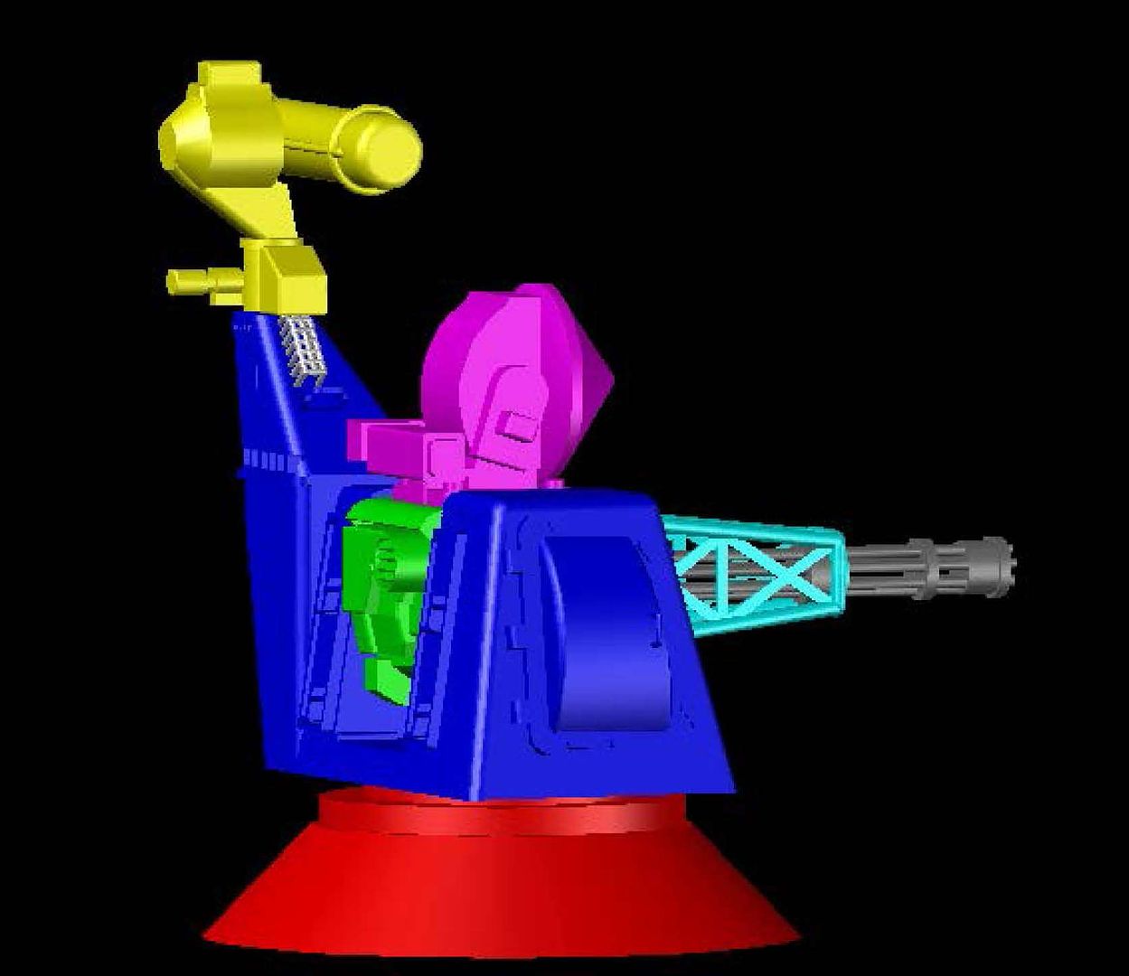 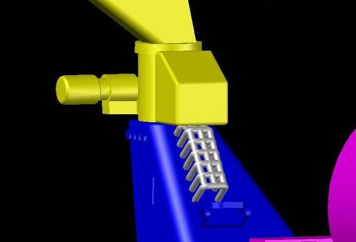 Pavel recommended making it solid. This was easily corrected because I had actually thought about this when I made it and already had the box I need saved on a miscellaneous layer, so I just recovered it…  …And joined it to the cage. 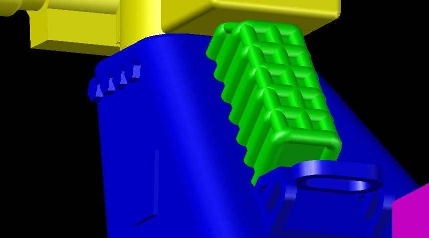 This will provide more support and still give the effect of a cage. 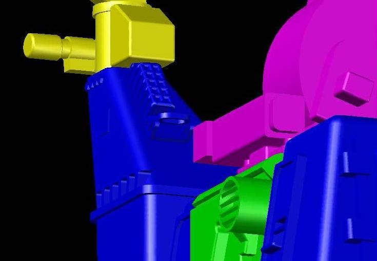 Another issue was the point at the bottom edge of the base, so I squared the edges by extruding a circle that I thought looked like it would cut the right amount off. 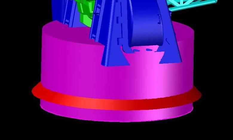 Then used the intersect command, producing the effect I was after. 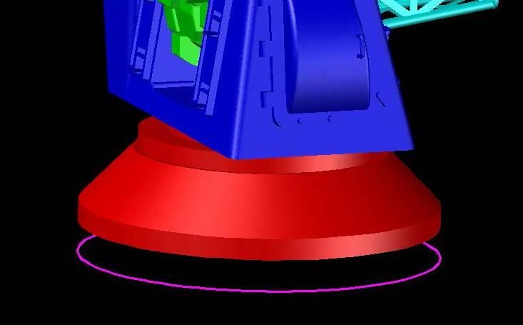 The next issue was the gun barrels that were too thin to be viable. The solution was to extrude a circle down the middle of them.   You can see that the individual barrels still stand out, but now they have internal support. This is when the wild hair hit me, so I extended the barrel spport past the end for attaching to the main gun body.  Thinking kit, I prepared to attach the gun barrels to the cage…  …First cutting out the hole for the barrel support. 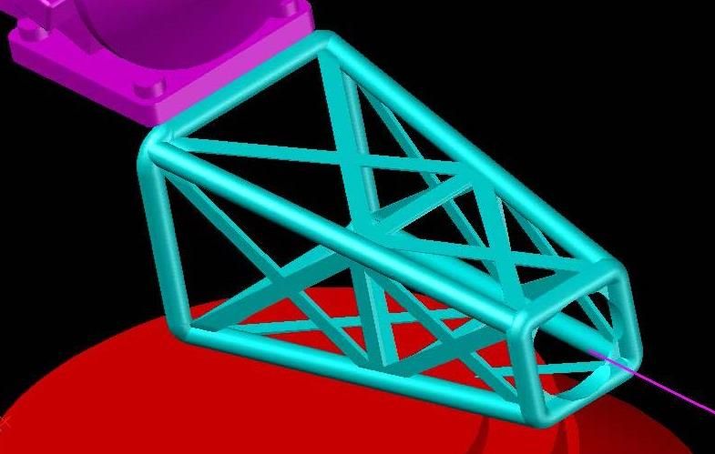 …And accommodating that same support, first with a collar… 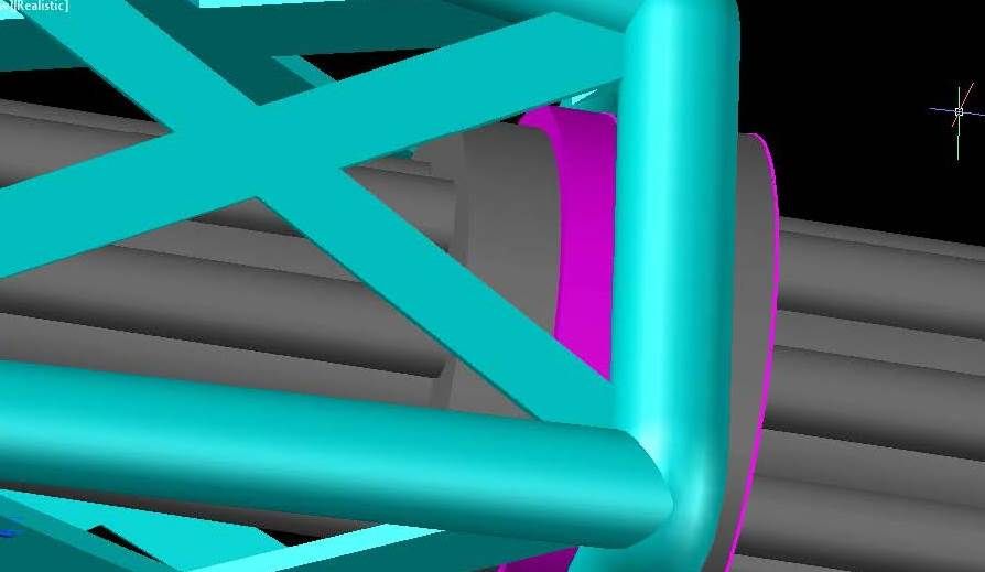 …Then the support for the collar to the cage. 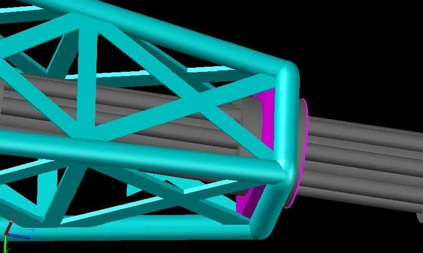  At this point I subtracted the gun from the features I had just added, leaving a socket for the gun to attach to. 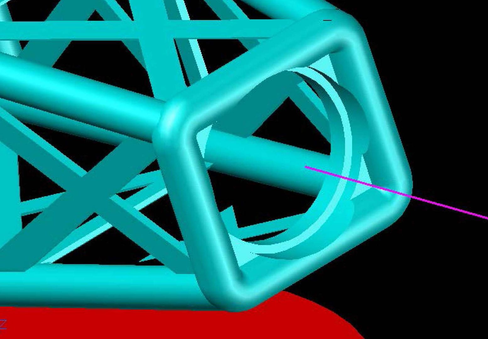 I copied the gun barrels back, and subtracted it again, this time from the gun base… 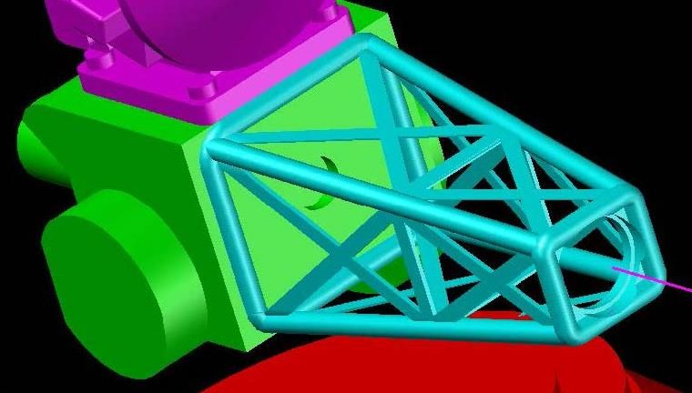 …Then copied the barrels back again. 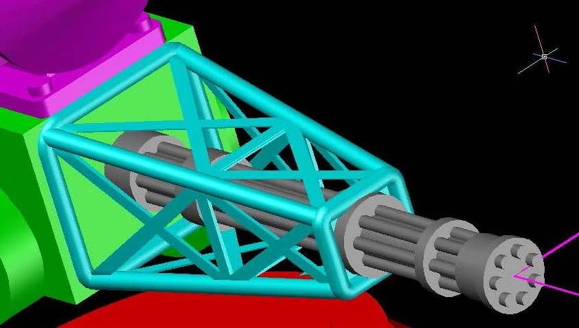 From here on, I made male and female connections for the various pieces, beginning with slots in the base of the radar arm. 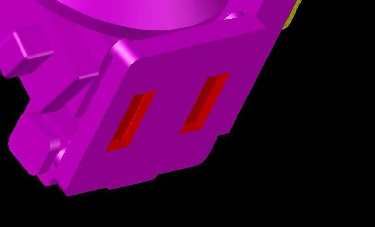 Using these slots, I extruded them out, to use to make the male connections on the gun barrel base. 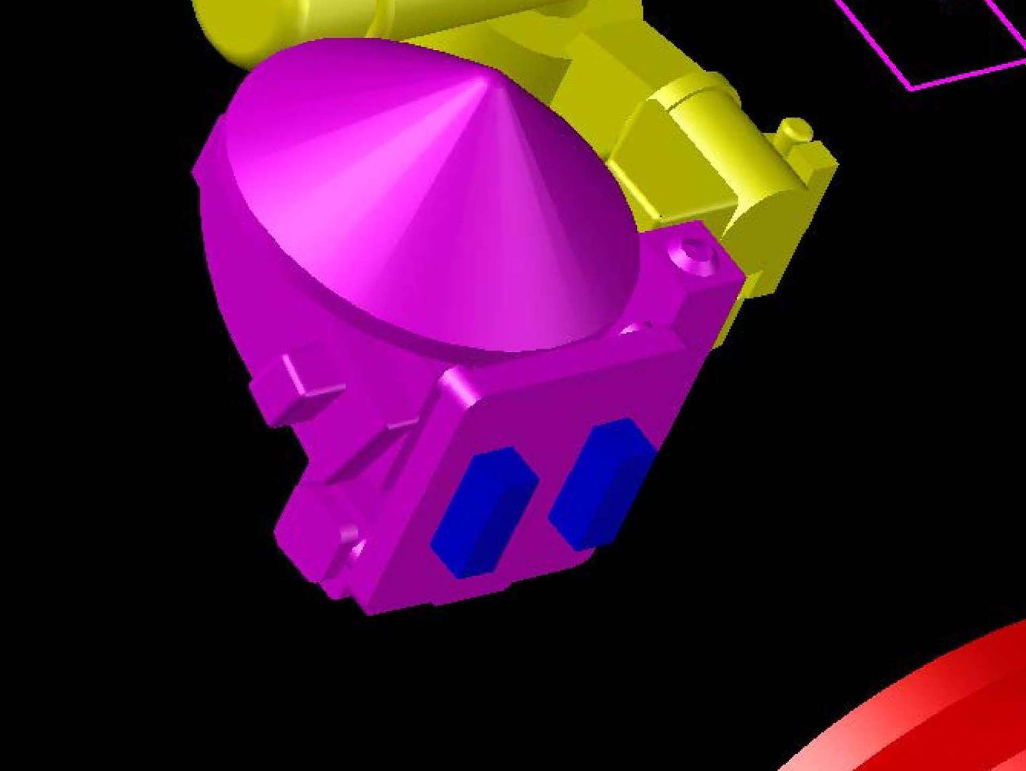 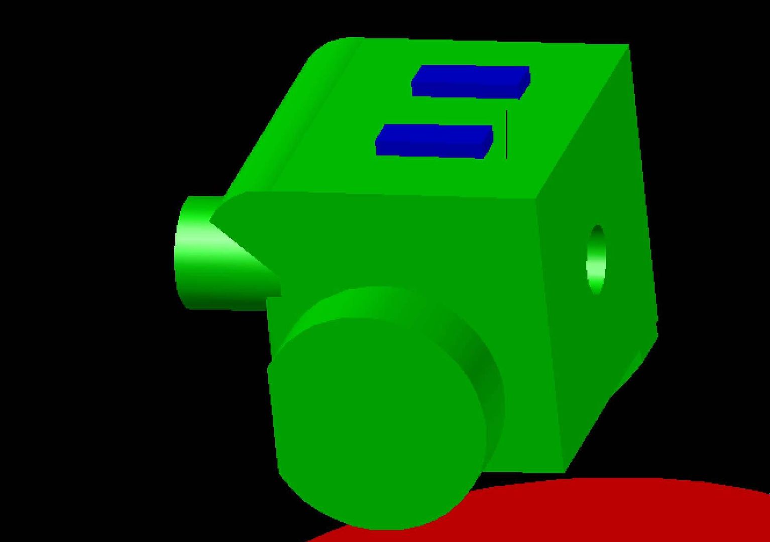 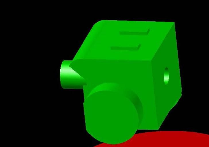 I then prepared to cut the holes in the main body to accommodate the gun base by copying the base to the side. 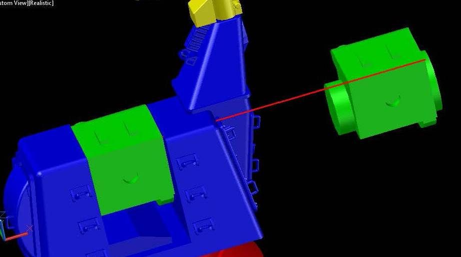 Because the protrusions on the gun body aren’t round I had to create the cylinders to be subtracted from the base. 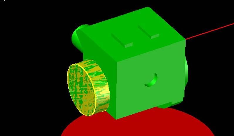 They are different size cylinders on the two sides.  Note in the previous two images that I had the layer that the body was turned off. Turning the layer back on and turning the gun body layer off shows the cylinders in position to be subtracted. 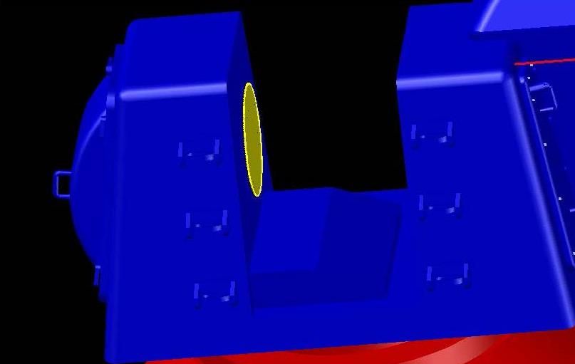 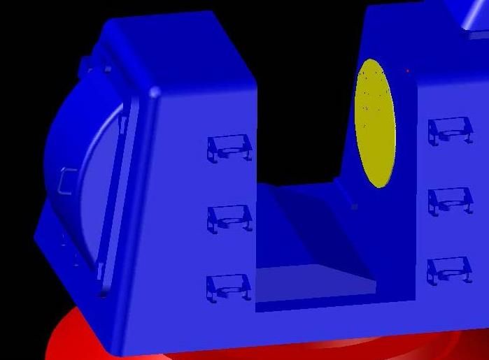 Which they then were. 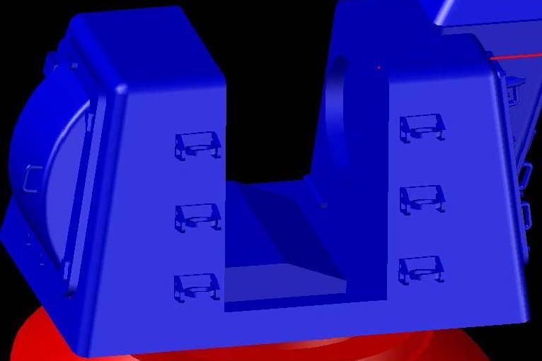 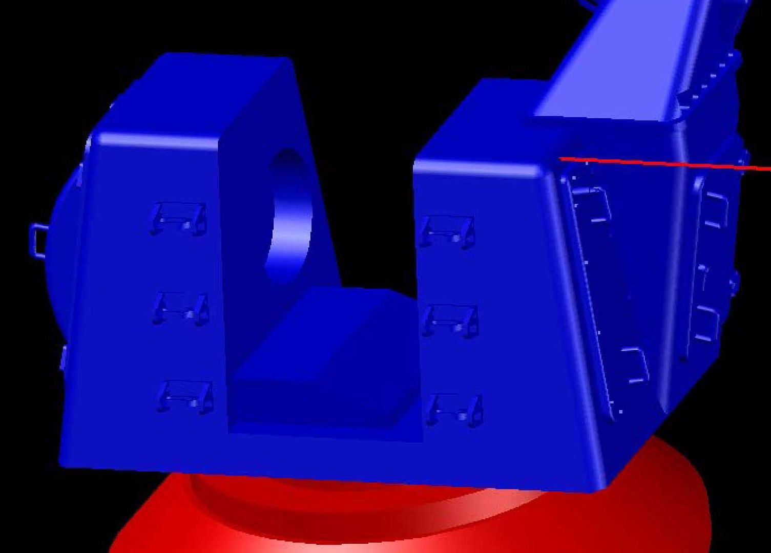 At this point I realized that I needed to divide the base into two parts to accommodate building the gun so the barrel was moveable, so I sliced it off. 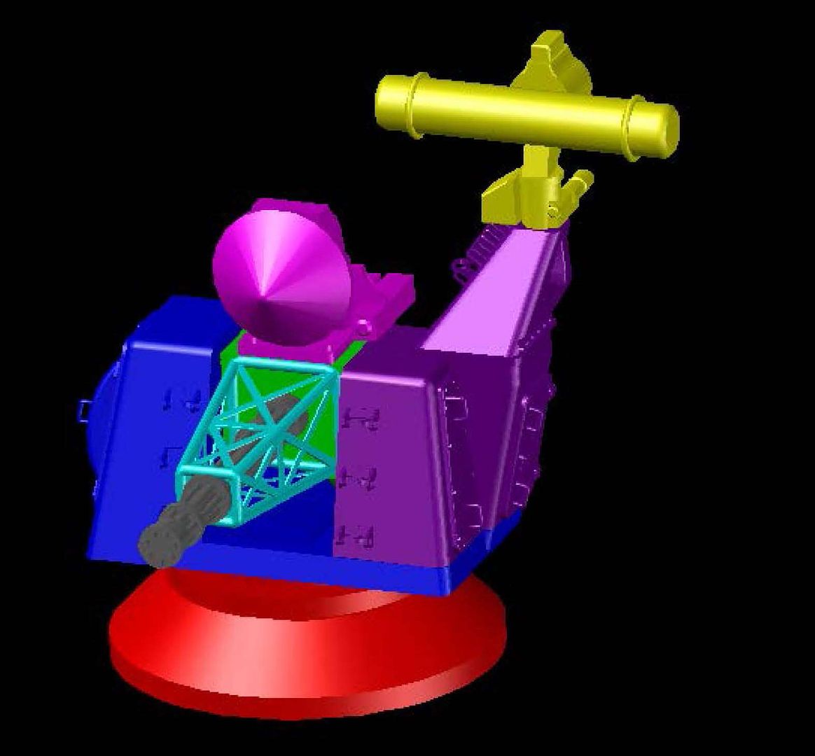 Next I made a female connection on the radar for attaching it to the arm… 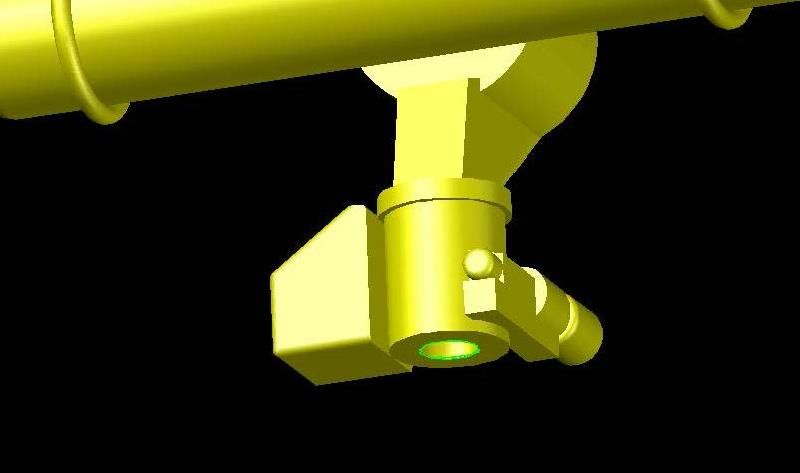 …And a male on the arm. 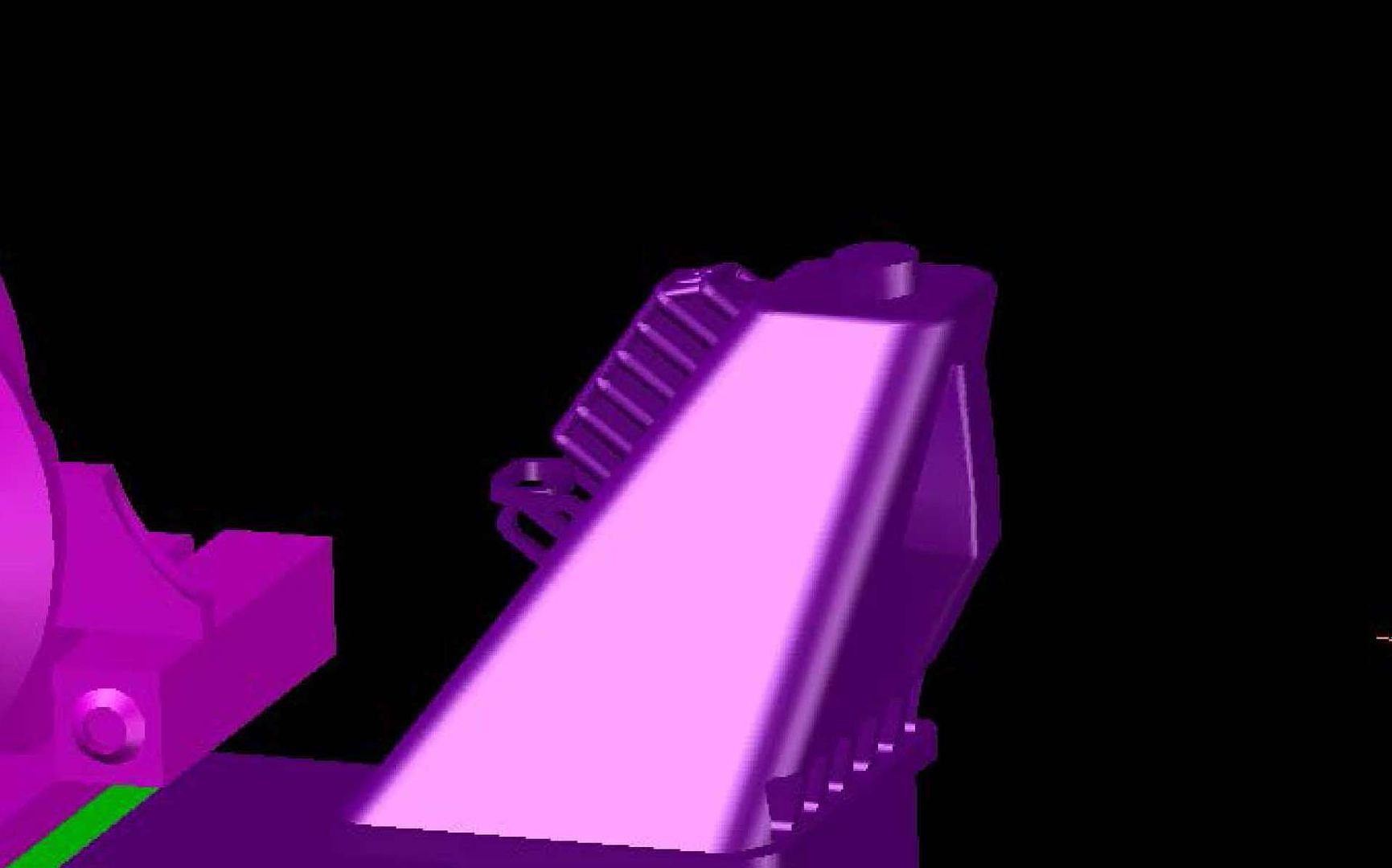 To mount the arm onto the base I first prepared the male portion on the base. 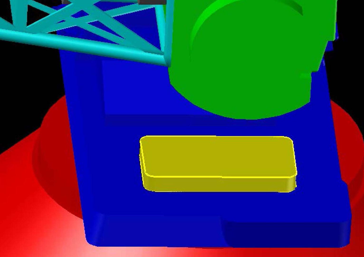 Then using this same shape cut out a female portion on the arm. 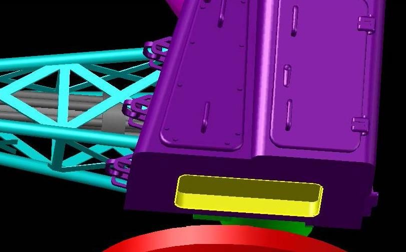 Next I added a male connector on the base in the form of lofted circles. 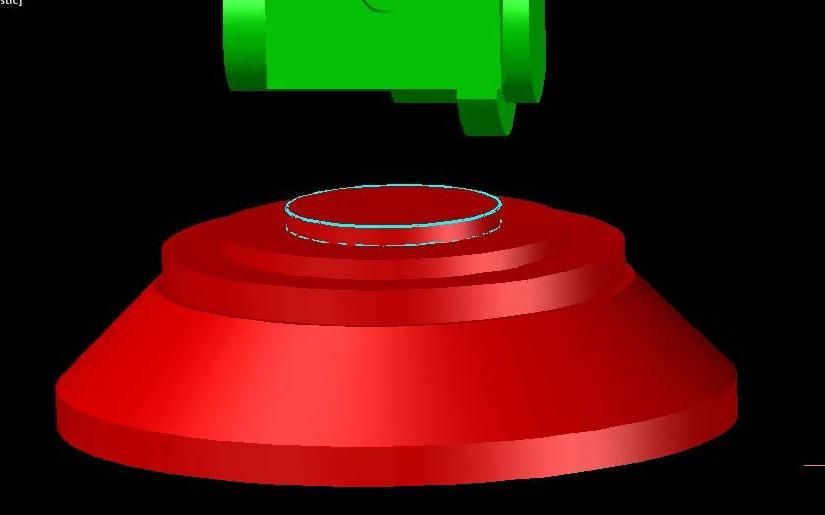 Then I used the same lofted circles to create the female portion on the bottom side of the base ,completing the process. 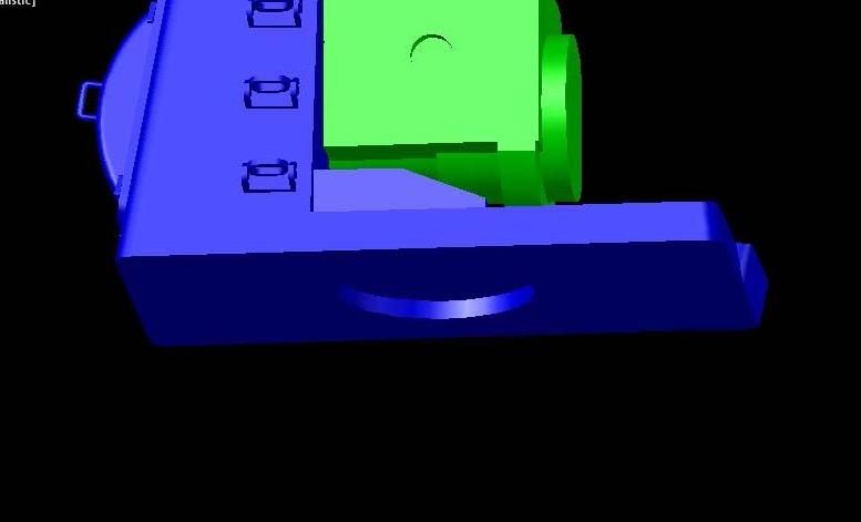 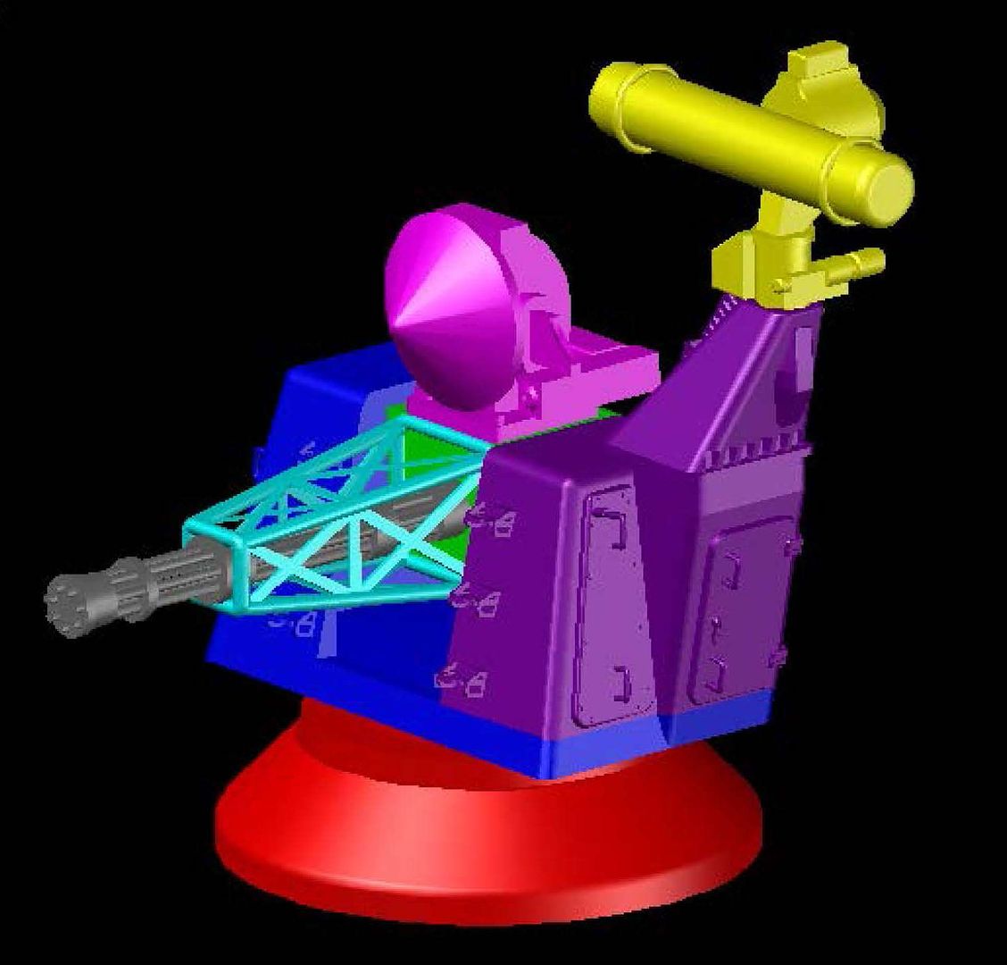 The image below shows the assembly exploded so you can see how everything goes together. 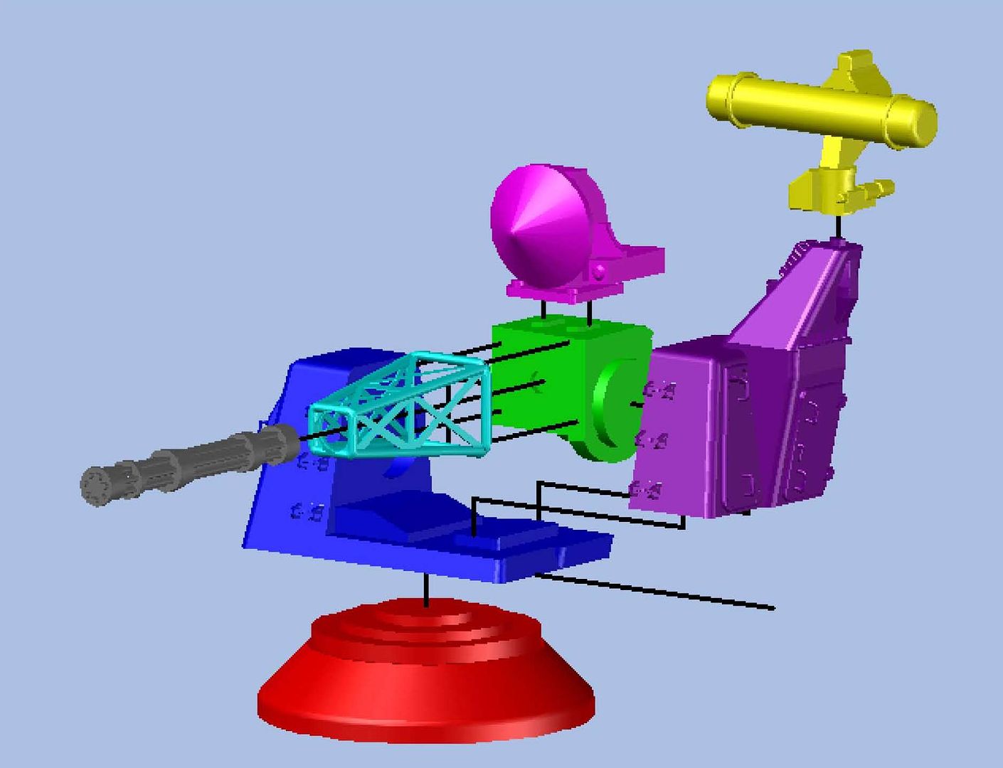 I realize that this is probably not practical at either 1//700 scale or 1/350 scale, but it was a fun exercise nevertheless and could be used at larger scales in the future. UPDATE 15
Hi Guys!
I haven’t seen it yet, but the first draft of the Goalkeeper was printed and I understand that it came out pretty good, with just a couple of minor issues that needed to be fixed. This post will describe the corrections that I made to make it better. I also got a crazy idea to make a kit out of it, even t though that probably isn’t feasible at the small scale of 1/350 and 1/700.
One of the things that was an issue was the cage near the top of the arm, below the radar.
[url=http://s1352.photobucket.com/user/rdutnell/media/Goalkeeper/GoalkeepWip15-Pix_Page_01_zps4d4a77db.jpg.html][img]http://i1352.photobucket.com/albums/q659/rdutnell/Goalkeeper/GoalkeepWip15-Pix_Page_01_zps4d4a77db.jpg[/img][/url]
[url=http://s1352.photobucket.com/user/rdutnell/media/Goalkeeper/GoalkeepWip15-Pix_Page_02_zpsaf3fa641.jpg.html][img]http://i1352.photobucket.com/albums/q659/rdutnell/Goalkeeper/GoalkeepWip15-Pix_Page_02_zpsaf3fa641.jpg[/img][/url]
Pavel recommended making it solid. This was easily corrected because I had actually thought about this when I made it and already had the box I need saved on a miscellaneous layer, so I just recovered it…
[url=http://s1352.photobucket.com/user/rdutnell/media/Goalkeeper/GoalkeepWip15-Pix_Page_03_zps1899586e.jpg.html][img]http://i1352.photobucket.com/albums/q659/rdutnell/Goalkeeper/GoalkeepWip15-Pix_Page_03_zps1899586e.jpg[/img][/url]
…And joined it to the cage.
[url=http://s1352.photobucket.com/user/rdutnell/media/Goalkeeper/GoalkeepWip15-Pix_Page_04_zps453f0dfd.jpg.html][img]http://i1352.photobucket.com/albums/q659/rdutnell/Goalkeeper/GoalkeepWip15-Pix_Page_04_zps453f0dfd.jpg[/img][/url]
This will provide more support and still give the effect of a cage.
[url=http://s1352.photobucket.com/user/rdutnell/media/Goalkeeper/GoalkeepWip15-Pix_Page_05_zpsb1d9f1c5.jpg.html][img]http://i1352.photobucket.com/albums/q659/rdutnell/Goalkeeper/GoalkeepWip15-Pix_Page_05_zpsb1d9f1c5.jpg[/img][/url]
Another issue was the point at the bottom edge of the base, so I squared the edges by extruding a circle that I thought looked like it would cut the right amount off.
[url=http://s1352.photobucket.com/user/rdutnell/media/Goalkeeper/GoalkeepWip15-Pix_Page_06_zpse22bc736.jpg.html][img]http://i1352.photobucket.com/albums/q659/rdutnell/Goalkeeper/GoalkeepWip15-Pix_Page_06_zpse22bc736.jpg[/img][/url]
Then used the intersect command, producing the effect I was after.
[url=http://s1352.photobucket.com/user/rdutnell/media/Goalkeeper/GoalkeepWip15-Pix_Page_07_zpsaea0b43e.jpg.html][img]http://i1352.photobucket.com/albums/q659/rdutnell/Goalkeeper/GoalkeepWip15-Pix_Page_07_zpsaea0b43e.jpg[/img][/url]
The next issue was the gun barrels that were too thin to be viable. The solution was to extrude a circle down the middle of them.
[url=http://s1352.photobucket.com/user/rdutnell/media/Goalkeeper/GoalkeepWip15-Pix_Page_08_zps90267de6.jpg.html][img]http://i1352.photobucket.com/albums/q659/rdutnell/Goalkeeper/GoalkeepWip15-Pix_Page_08_zps90267de6.jpg[/img][/url]
[url=http://s1352.photobucket.com/user/rdutnell/media/Goalkeeper/GoalkeepWip15-Pix_Page_09_zps71cf5455.jpg.html][img]http://i1352.photobucket.com/albums/q659/rdutnell/Goalkeeper/GoalkeepWip15-Pix_Page_09_zps71cf5455.jpg[/img][/url]
You can see that the individual barrels still stand out, but now they have internal support. This is when the wild hair hit me, so I extended the barrel spport past the end for attaching to the main gun body.
[url=http://s1352.photobucket.com/user/rdutnell/media/Goalkeeper/GoalkeepWip15-Pix_Page_10_zpsb24b0ae3.jpg.html][img]http://i1352.photobucket.com/albums/q659/rdutnell/Goalkeeper/GoalkeepWip15-Pix_Page_10_zpsb24b0ae3.jpg[/img][/url]
Thinking kit, I prepared to attach the gun barrels to the cage…
[url=http://s1352.photobucket.com/user/rdutnell/media/Goalkeeper/GoalkeepWip15-Pix_Page_11_zpse014599b.jpg.html][img]http://i1352.photobucket.com/albums/q659/rdutnell/Goalkeeper/GoalkeepWip15-Pix_Page_11_zpse014599b.jpg[/img][/url]
…First cutting out the hole for the barrel support.
[url=http://s1352.photobucket.com/user/rdutnell/media/Goalkeeper/GoalkeepWip15-Pix_Page_12_zpsee3630ed.jpg.html][img]http://i1352.photobucket.com/albums/q659/rdutnell/Goalkeeper/GoalkeepWip15-Pix_Page_12_zpsee3630ed.jpg[/img][/url]
…And accommodating that same support, first with a collar…
[url=http://s1352.photobucket.com/user/rdutnell/media/Goalkeeper/GoalkeepWip15-Pix_Page_13_zpsaa942fea.jpg.html][img]http://i1352.photobucket.com/albums/q659/rdutnell/Goalkeeper/GoalkeepWip15-Pix_Page_13_zpsaa942fea.jpg[/img][/url]
…Then the support for the collar to the cage.
[url=http://s1352.photobucket.com/user/rdutnell/media/Goalkeeper/GoalkeepWip15-Pix_Page_14_zps03b622c7.jpg.html][img]http://i1352.photobucket.com/albums/q659/rdutnell/Goalkeeper/GoalkeepWip15-Pix_Page_14_zps03b622c7.jpg[/img][/url]
[url=http://s1352.photobucket.com/user/rdutnell/media/Goalkeeper/GoalkeepWip15-Pix_Page_15_zps63331049.jpg.html][img]http://i1352.photobucket.com/albums/q659/rdutnell/Goalkeeper/GoalkeepWip15-Pix_Page_15_zps63331049.jpg[/img][/url]
At this point I subtracted the gun from the features I had just added, leaving a socket for the gun to attach to.
[url=http://s1352.photobucket.com/user/rdutnell/media/Goalkeeper/GoalkeepWip15-Pix_Page_16_zps784962b0.jpg.html][img]http://i1352.photobucket.com/albums/q659/rdutnell/Goalkeeper/GoalkeepWip15-Pix_Page_16_zps784962b0.jpg[/img][/url]
I copied the gun barrels back, and subtracted it again, this time from the gun base…
[url=http://s1352.photobucket.com/user/rdutnell/media/Goalkeeper/GoalkeepWip15-Pix_Page_17_zps5ee37888.jpg.html][img]http://i1352.photobucket.com/albums/q659/rdutnell/Goalkeeper/GoalkeepWip15-Pix_Page_17_zps5ee37888.jpg[/img][/url]
…Then copied the barrels back again.
[url=http://s1352.photobucket.com/user/rdutnell/media/Goalkeeper/GoalkeepWip15-Pix_Page_18_zpsabcc40ac.jpg.html][img]http://i1352.photobucket.com/albums/q659/rdutnell/Goalkeeper/GoalkeepWip15-Pix_Page_18_zpsabcc40ac.jpg[/img][/url]
From here on, I made male and female connections for the various pieces, beginning with slots in the base of the radar arm.
[url=http://s1352.photobucket.com/user/rdutnell/media/Goalkeeper/GoalkeepWip15-Pix_Page_19_zps6467e768.jpg.html][img]http://i1352.photobucket.com/albums/q659/rdutnell/Goalkeeper/GoalkeepWip15-Pix_Page_19_zps6467e768.jpg[/img][/url]
Using these slots, I extruded them out, to use to make the male connections on the gun barrel base.
[url=http://s1352.photobucket.com/user/rdutnell/media/Goalkeeper/GoalkeepWip15-Pix_Page_20_zpse468f460.jpg.html][img]http://i1352.photobucket.com/albums/q659/rdutnell/Goalkeeper/GoalkeepWip15-Pix_Page_20_zpse468f460.jpg[/img][/url]
[url=http://s1352.photobucket.com/user/rdutnell/media/Goalkeeper/GoalkeepWip15-Pix_Page_21_zps1f97abdb.jpg.html][img]http://i1352.photobucket.com/albums/q659/rdutnell/Goalkeeper/GoalkeepWip15-Pix_Page_21_zps1f97abdb.jpg[/img][/url]
[url=http://s1352.photobucket.com/user/rdutnell/media/Goalkeeper/GoalkeepWip15-Pix_Page_22_zpsc157f485.jpg.html][img]http://i1352.photobucket.com/albums/q659/rdutnell/Goalkeeper/GoalkeepWip15-Pix_Page_22_zpsc157f485.jpg[/img][/url]
I then prepared to cut the holes in the main body to accommodate the gun base by copying the base to the side.
[url=http://s1352.photobucket.com/user/rdutnell/media/Goalkeeper/GoalkeepWip15-Pix_Page_23_zpsf9b71633.jpg.html][img]http://i1352.photobucket.com/albums/q659/rdutnell/Goalkeeper/GoalkeepWip15-Pix_Page_23_zpsf9b71633.jpg[/img][/url]
Because the protrusions on the gun body aren’t round I had to create the cylinders to be subtracted from the base.
[url=http://s1352.photobucket.com/user/rdutnell/media/Goalkeeper/GoalkeepWip15-Pix_Page_24_zpsbed1ea0c.jpg.html][img]http://i1352.photobucket.com/albums/q659/rdutnell/Goalkeeper/GoalkeepWip15-Pix_Page_24_zpsbed1ea0c.jpg[/img][/url]
They are different size cylinders on the two sides.
[url=http://s1352.photobucket.com/user/rdutnell/media/Goalkeeper/GoalkeepWip15-Pix_Page_25_zpsbeb43cc6.jpg.html][img]http://i1352.photobucket.com/albums/q659/rdutnell/Goalkeeper/GoalkeepWip15-Pix_Page_25_zpsbeb43cc6.jpg[/img][/url]
Note in the previous two images that I had the layer that the body was turned off. Turning the layer back on and turning the gun body layer off shows the cylinders in position to be subtracted.
[url=http://s1352.photobucket.com/user/rdutnell/media/Goalkeeper/GoalkeepWip15-Pix_Page_26_zpse5afd600.jpg.html][img]http://i1352.photobucket.com/albums/q659/rdutnell/Goalkeeper/GoalkeepWip15-Pix_Page_26_zpse5afd600.jpg[/img][/url]
[url=http://s1352.photobucket.com/user/rdutnell/media/Goalkeeper/GoalkeepWip15-Pix_Page_27_zps5743d40e.jpg.html][img]http://i1352.photobucket.com/albums/q659/rdutnell/Goalkeeper/GoalkeepWip15-Pix_Page_27_zps5743d40e.jpg[/img][/url]
Which they then were.
[url=http://s1352.photobucket.com/user/rdutnell/media/Goalkeeper/GoalkeepWip15-Pix_Page_28_zps56117399.jpg.html][img]http://i1352.photobucket.com/albums/q659/rdutnell/Goalkeeper/GoalkeepWip15-Pix_Page_28_zps56117399.jpg[/img][/url]
[url=http://s1352.photobucket.com/user/rdutnell/media/Goalkeeper/GoalkeepWip15-Pix_Page_29_zps47a98194.jpg.html][img]http://i1352.photobucket.com/albums/q659/rdutnell/Goalkeeper/GoalkeepWip15-Pix_Page_29_zps47a98194.jpg[/img][/url]
At this point I realized that I needed to divide the base into two parts to accommodate building the gun so the barrel was moveable, so I sliced it off.
[url=http://s1352.photobucket.com/user/rdutnell/media/Goalkeeper/GoalkeepWip15-Pix_Page_30_zps375ba0ba.jpg.html][img]http://i1352.photobucket.com/albums/q659/rdutnell/Goalkeeper/GoalkeepWip15-Pix_Page_30_zps375ba0ba.jpg[/img][/url]
Next I made a female connection on the radar for attaching it to the arm…
[url=http://s1352.photobucket.com/user/rdutnell/media/Goalkeeper/GoalkeepWip15-Pix_Page_31_zps20e0fed6.jpg.html][img]http://i1352.photobucket.com/albums/q659/rdutnell/Goalkeeper/GoalkeepWip15-Pix_Page_31_zps20e0fed6.jpg[/img][/url]
…And a male on the arm.
[url=http://s1352.photobucket.com/user/rdutnell/media/Goalkeeper/GoalkeepWip15-Pix_Page_32_zpse7a91b45.jpg.html][img]http://i1352.photobucket.com/albums/q659/rdutnell/Goalkeeper/GoalkeepWip15-Pix_Page_32_zpse7a91b45.jpg[/img][/url]
To mount the arm onto the base I first prepared the male portion on the base.
[url=http://s1352.photobucket.com/user/rdutnell/media/Goalkeeper/GoalkeepWip15-Pix_Page_33_zps603aba13.jpg.html][img]http://i1352.photobucket.com/albums/q659/rdutnell/Goalkeeper/GoalkeepWip15-Pix_Page_33_zps603aba13.jpg[/img][/url]
Then using this same shape cut out a female portion on the arm.
[url=http://s1352.photobucket.com/user/rdutnell/media/Goalkeeper/GoalkeepWip15-Pix_Page_34_zpsf3edb246.jpg.html][img]http://i1352.photobucket.com/albums/q659/rdutnell/Goalkeeper/GoalkeepWip15-Pix_Page_34_zpsf3edb246.jpg[/img][/url]
Next I added a male connector on the base in the form of lofted circles.
[url=http://s1352.photobucket.com/user/rdutnell/media/Goalkeeper/GoalkeepWip15-Pix_Page_35_zps378de7d9.jpg.html][img]http://i1352.photobucket.com/albums/q659/rdutnell/Goalkeeper/GoalkeepWip15-Pix_Page_35_zps378de7d9.jpg[/img][/url]
Then I used the same lofted circles to create the female portion on the bottom side of the base ,completing the process.
[url=http://s1352.photobucket.com/user/rdutnell/media/Goalkeeper/GoalkeepWip15-Pix_Page_36_zpse2209ace.jpg.html][img]http://i1352.photobucket.com/albums/q659/rdutnell/Goalkeeper/GoalkeepWip15-Pix_Page_36_zpse2209ace.jpg[/img][/url]
[url=http://s1352.photobucket.com/user/rdutnell/media/Goalkeeper/GoalkeepWip15-Pix_Page_37_zps2798ba4f.jpg.html][img]http://i1352.photobucket.com/albums/q659/rdutnell/Goalkeeper/GoalkeepWip15-Pix_Page_37_zps2798ba4f.jpg[/img][/url]
The image below shows the assembly exploded so you can see how everything goes together.
[url=http://s1352.photobucket.com/user/rdutnell/media/Goalkeeper/GoalkeepWip15-Pix_Page_38_zpsa6cf3bb1.jpg.html][img]http://i1352.photobucket.com/albums/q659/rdutnell/Goalkeeper/GoalkeepWip15-Pix_Page_38_zpsa6cf3bb1.jpg[/img][/url]
I realize that this is probably not practical at either 1//700 scale or 1/350 scale, but it was a fun exercise nevertheless and could be used at larger scales in the future.
|
|
|
|
Posted: Sun Jun 16, 2013 1:05 am |
|
|
|
|
|
| |
Post subject: |
Re: 1/350 Goalkeeper close-in weapon system (CIWS) in AutoCa |
|
|
Thanks Michael! I’m glad you liked it. As I said in the introduction, I post my projects because it helps me build a better model, through reflection, and often times great input, although I didn’t really receive much on this project. (That’s good, right?) I also post because I always enjoy looking at other people’s posts and figure that others, such as yourself, would enjoy seeing the steps I follow. As for your printing question, I did this project for Admiralty Model Works ( http://www.admiraltymodelworks.com/admiral/) in exchange for printing some of my detailed Greenling model. They have a new state-of-the-art ProJet 3500HD Max, a very expensive Rapid Prototype machine that will do 16 micron layers. Give them a shout. They may be able to help you with your 3D printing needs. CHEERS!!! Thanks Michael! I’m glad you liked it.
As I said in the introduction, I post my projects because it helps me build a better model, through reflection, and often times great input, although I didn’t really receive much on this project. (That’s good, right?) I also post because I always enjoy looking at other people’s posts and figure that others, such as yourself, would enjoy seeing the steps I follow.
As for your printing question, I did this project for Admiralty Model Works (http://www.admiraltymodelworks.com/admiral/) in exchange for printing some of my detailed Greenling model. They have a new state-of-the-art ProJet 3500HD Max, a very expensive Rapid Prototype machine that will do 16 micron layers. Give them a shout. They may be able to help you with your 3D printing needs.
CHEERS!!!
|
|
|
|
Posted: Mon Jun 03, 2013 6:32 pm |
|
|
|
|
|
| |
Post subject: |
Re: 1/350 Goalkeeper close-in weapon system (CIWS) in AutoCa |
|
|
|
Amazing work, congratulations! I particularly appreciated the step by step presentation throughout. Have you in mind a 3D printing supplier? I would like to learn who could do this type of work. Michael
Amazing work, congratulations! I particularly appreciated the step by step presentation throughout. Have you in mind a 3D printing supplier? I would like to learn who could do this type of work. Michael
|
|
|
|
Posted: Mon Jun 03, 2013 2:37 pm |
|
|
|
|
|
| |
Post subject: |
Re: 1/350 Goalkeeper close-in weapon system (CIWS) in AutoCa |
|
|
|
[u][b]UPDATE 14[/b][/u]
Hi Guys!
Here are the images of the completed Goalkeeper as I promised. I hope you enjoyed this little adventure as much as I did. Enjoy!
[url=http://s1352.photobucket.com/user/rdutnell/media/Goalkeeper/pix14_Page_01_zps6e212473.jpg.html][img]http://i1352.photobucket.com/albums/q659/rdutnell/Goalkeeper/pix14_Page_01_zps6e212473.jpg[/img][/url]
[url=http://s1352.photobucket.com/user/rdutnell/media/Goalkeeper/pix14_Page_02_zps5a0a3687.jpg.html][img]http://i1352.photobucket.com/albums/q659/rdutnell/Goalkeeper/pix14_Page_02_zps5a0a3687.jpg[/img][/url]
[url=http://s1352.photobucket.com/user/rdutnell/media/Goalkeeper/pix14_Page_03_zps16345ca5.jpg.html][img]http://i1352.photobucket.com/albums/q659/rdutnell/Goalkeeper/pix14_Page_03_zps16345ca5.jpg[/img][/url]
[url=http://s1352.photobucket.com/user/rdutnell/media/Goalkeeper/pix14_Page_04_zps19a7cc4b.jpg.html][img]http://i1352.photobucket.com/albums/q659/rdutnell/Goalkeeper/pix14_Page_04_zps19a7cc4b.jpg[/img][/url]
[url=http://s1352.photobucket.com/user/rdutnell/media/Goalkeeper/pix14_Page_05_zpsf7a46291.jpg.html][img]http://i1352.photobucket.com/albums/q659/rdutnell/Goalkeeper/pix14_Page_05_zpsf7a46291.jpg[/img][/url]
[url=http://s1352.photobucket.com/user/rdutnell/media/Goalkeeper/pix14_Page_06_zps7fc495a8.jpg.html][img]http://i1352.photobucket.com/albums/q659/rdutnell/Goalkeeper/pix14_Page_06_zps7fc495a8.jpg[/img][/url]
[url=http://s1352.photobucket.com/user/rdutnell/media/Goalkeeper/pix14_Page_07_zps9e16b1a8.jpg.html][img]http://i1352.photobucket.com/albums/q659/rdutnell/Goalkeeper/pix14_Page_07_zps9e16b1a8.jpg[/img][/url]
[url=http://s1352.photobucket.com/user/rdutnell/media/Goalkeeper/pix14_Page_08_zps09c2260a.jpg.html][img]http://i1352.photobucket.com/albums/q659/rdutnell/Goalkeeper/pix14_Page_08_zps09c2260a.jpg[/img][/url]
[url=http://s1352.photobucket.com/user/rdutnell/media/Goalkeeper/pix14_Page_09_zpsae5c9360.jpg.html][img]http://i1352.photobucket.com/albums/q659/rdutnell/Goalkeeper/pix14_Page_09_zpsae5c9360.jpg[/img][/url]
[url=http://s1352.photobucket.com/user/rdutnell/media/Goalkeeper/pix14_Page_10_zps92acc16f.jpg.html][img]http://i1352.photobucket.com/albums/q659/rdutnell/Goalkeeper/pix14_Page_10_zps92acc16f.jpg[/img][/url]
[url=http://s1352.photobucket.com/user/rdutnell/media/Goalkeeper/pix14_Page_11_zps7804e36b.jpg.html][img]http://i1352.photobucket.com/albums/q659/rdutnell/Goalkeeper/pix14_Page_11_zps7804e36b.jpg[/img][/url]
[url=http://s1352.photobucket.com/user/rdutnell/media/Goalkeeper/pix14_Page_12_zps179e2bb7.jpg.html][img]http://i1352.photobucket.com/albums/q659/rdutnell/Goalkeeper/pix14_Page_12_zps179e2bb7.jpg[/img][/url]
I also promised you a little surprise. Click on the image below to see a short video of the Goalkeeper.
[url=http://i1352.photobucket.com/albums/q659/rdutnell/Goalkeeper/GoalKeeperVideo1_zpsdac5ab7f.mp4][img]http://i1352.photobucket.com/albums/q659/rdutnell/Goalkeeper/th_GoalKeeperVideo1_zpsdac5ab7f.jpg[/img][/url]
If you see anything missing or something that isn’t correct, please let me know.
CHEERS!!!
|
|
|
|
Posted: Mon Jun 03, 2013 11:56 am |
|
|
|
|
|
| |
Post subject: |
Re: 1/350 Goalkeeper close-in weapon system (CIWS) in AutoCa |
|
|
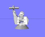
UPDATE 13Hi guys! I got on a roll last night and completed the Goalkeeper, or I should say that I completed the first draft of it. I could have missed something, or done something wrong, or perhaps get pictures to better show a couple of areas that I adlibbed due to lack of good images of them. The grabs on the front and the wing nuts on the side come to mind. Anyway, here is the rest of the build. It’s quite a long post, so sit back and enjoy. Here is the way the back looked based on the line drawings I used. 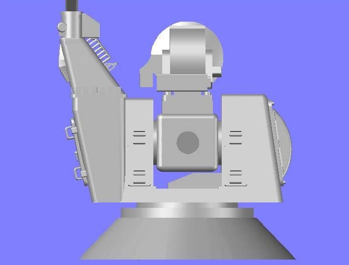 The first thing I noticed is that the barrel was too low, so I moved it up. 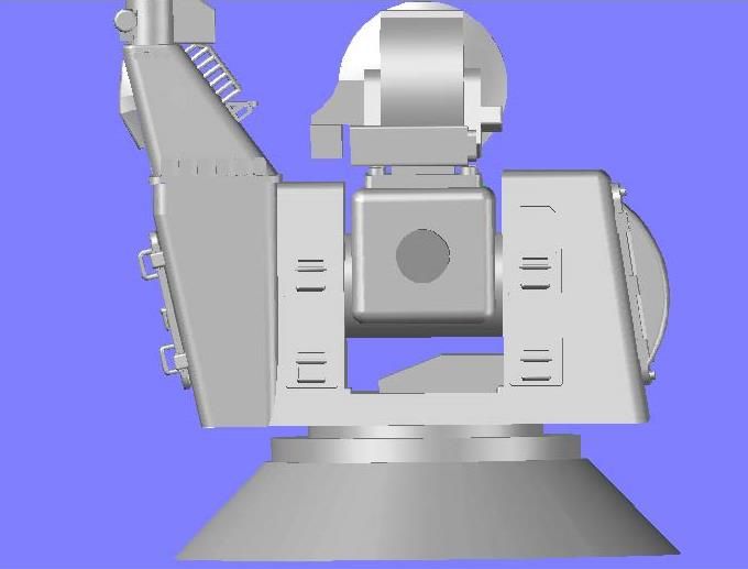 The next thing I did was slice the back of the barrel off even with the back edge of the top plate. 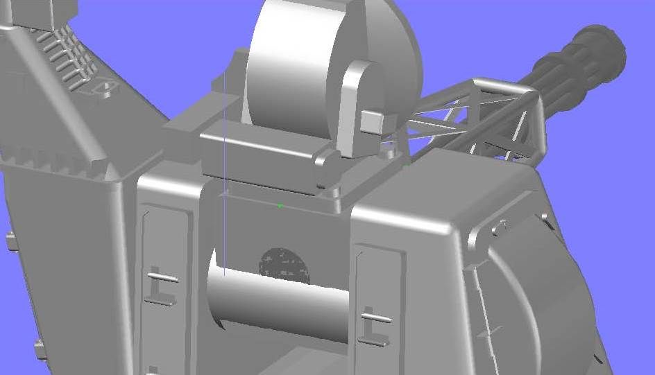 Also, the barrel seemed too thin, so I widened it. Well, I didn’t actually widen it, I made a new one with the same height, but wider. 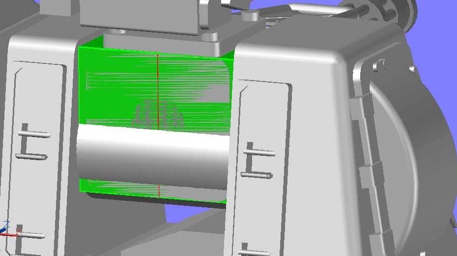 I also sliced off the shaft. 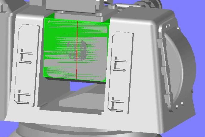 I built the back up in layers, with the exception of the exhaust tube on the upper right, which I drew first, followed by the outline of the first level. 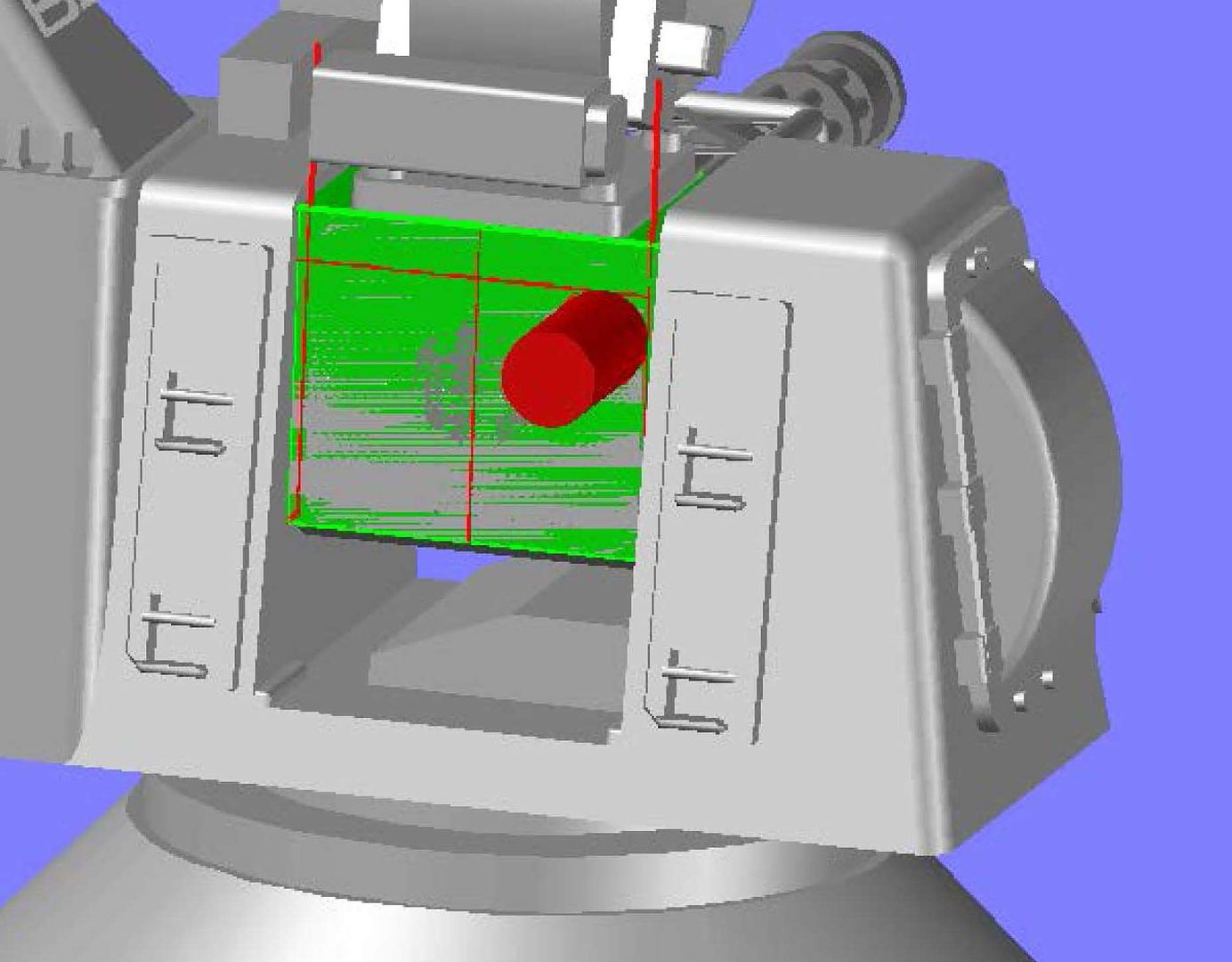 I then extruded the first level… 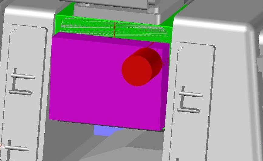 The upper right corner of the first level follows the outline of the exhaust tube, so I filleted the edge to match. 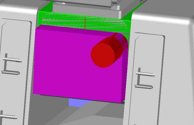 The first level actually has a notch cut in the bottom right corner, so I cut it out to match the photo. 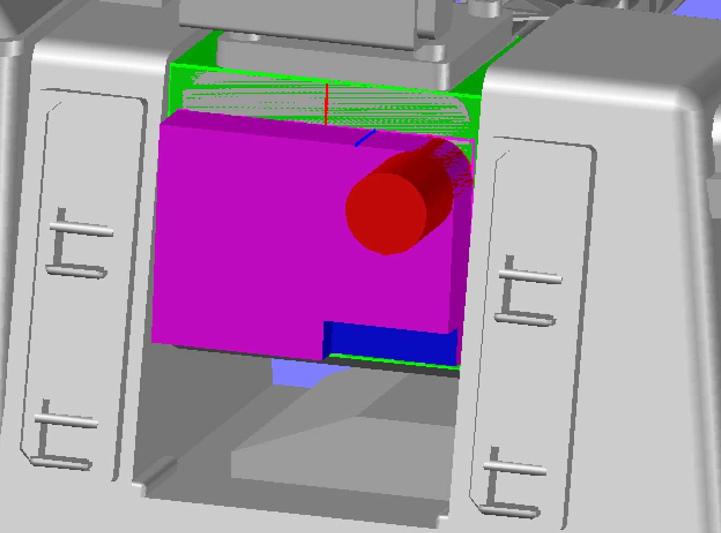 Next, I traced out the outline of the second level and extruded it. As I was doing this I realized that the exhaust vent was too small so I made it larger. 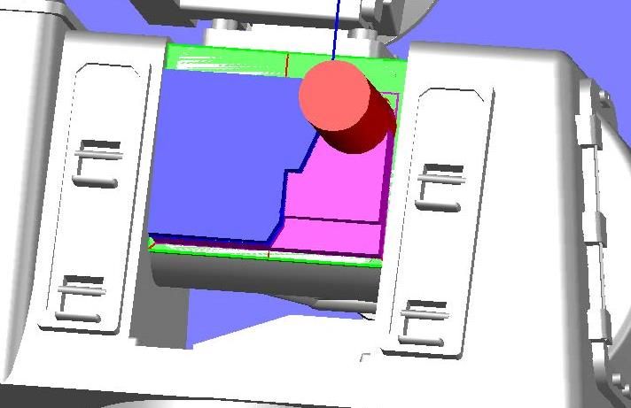 The lower part of the second level is sloped, so I sliced off the end. 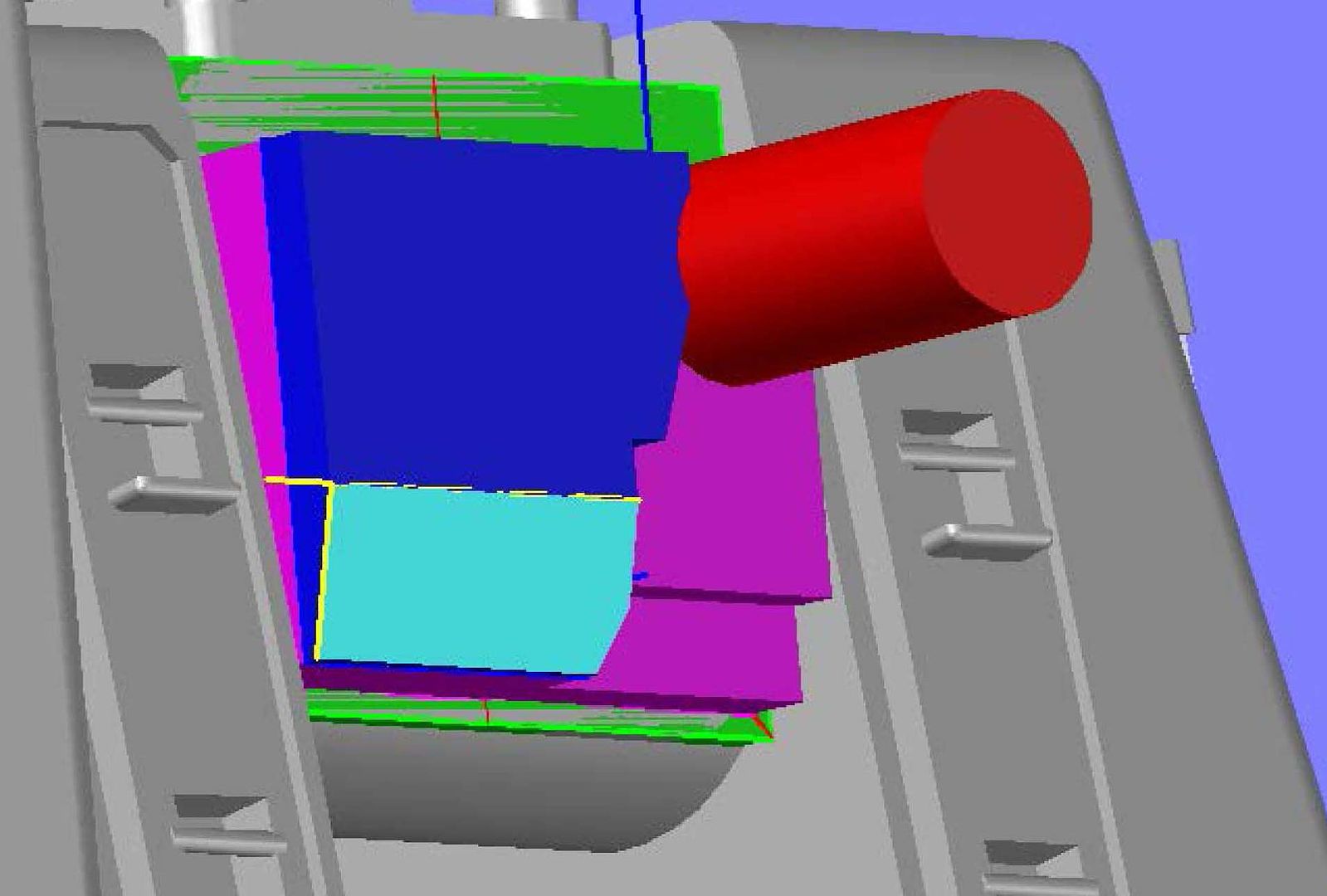 About this time I realized that my layers were too thick, so I sliced them thinner. 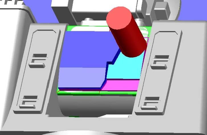 The last level was the most difficult to do, but I started by extruding the outline shown below in yellow. 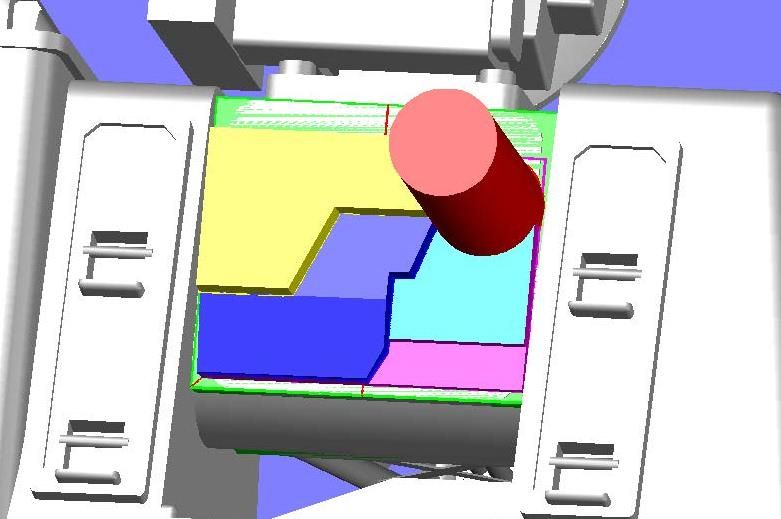 A section on the lower right of the top level slopes down to the second level, so I prepared to do this by drawing a properly sized rectangle at the top of the slope and copied it down to the location of the bottom of the slope… 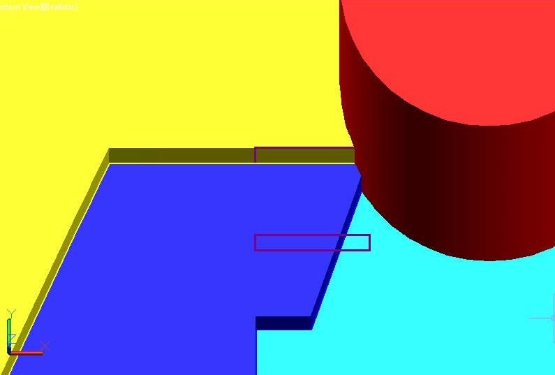 …Moved the lower one into the lower level and lofted them. 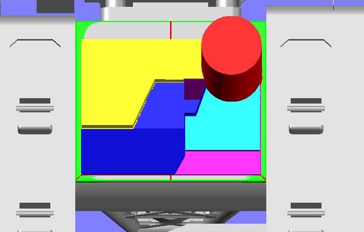 The top level also has a cutout at the top. I created this by drawing a polygon, filleting the corners, extruding the shape… 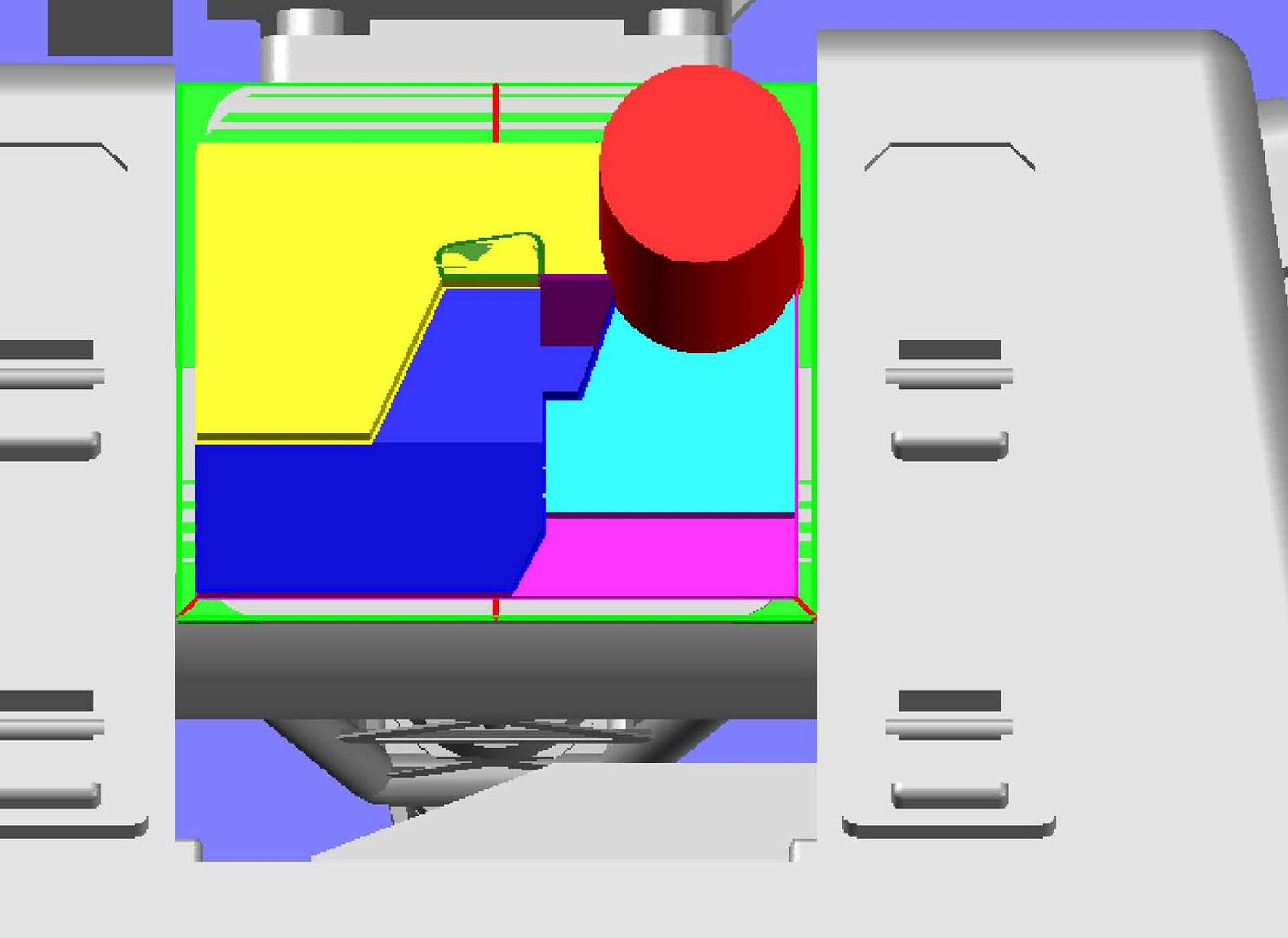 …And subtracting it. 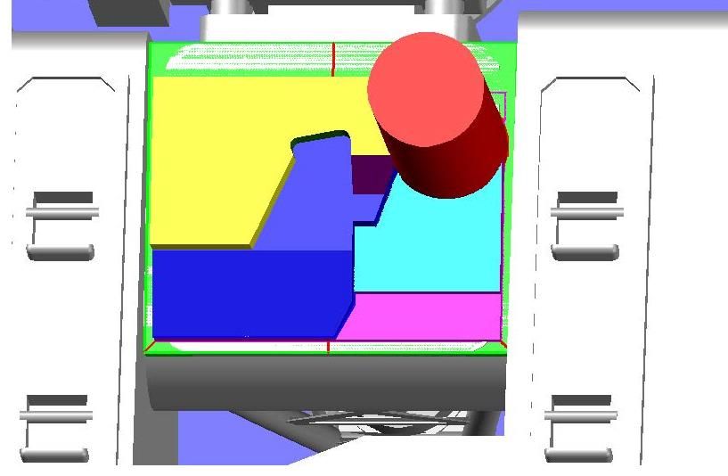 In the bottom left hand corner, there is a plate that extrudes up from the second level, but not all the way up to the third level. It is sloped like the lower part of the second level. Once I got the coordinate system lined up properly this was easily done by drawing a rectangle on the face of the slope and extruding it up. 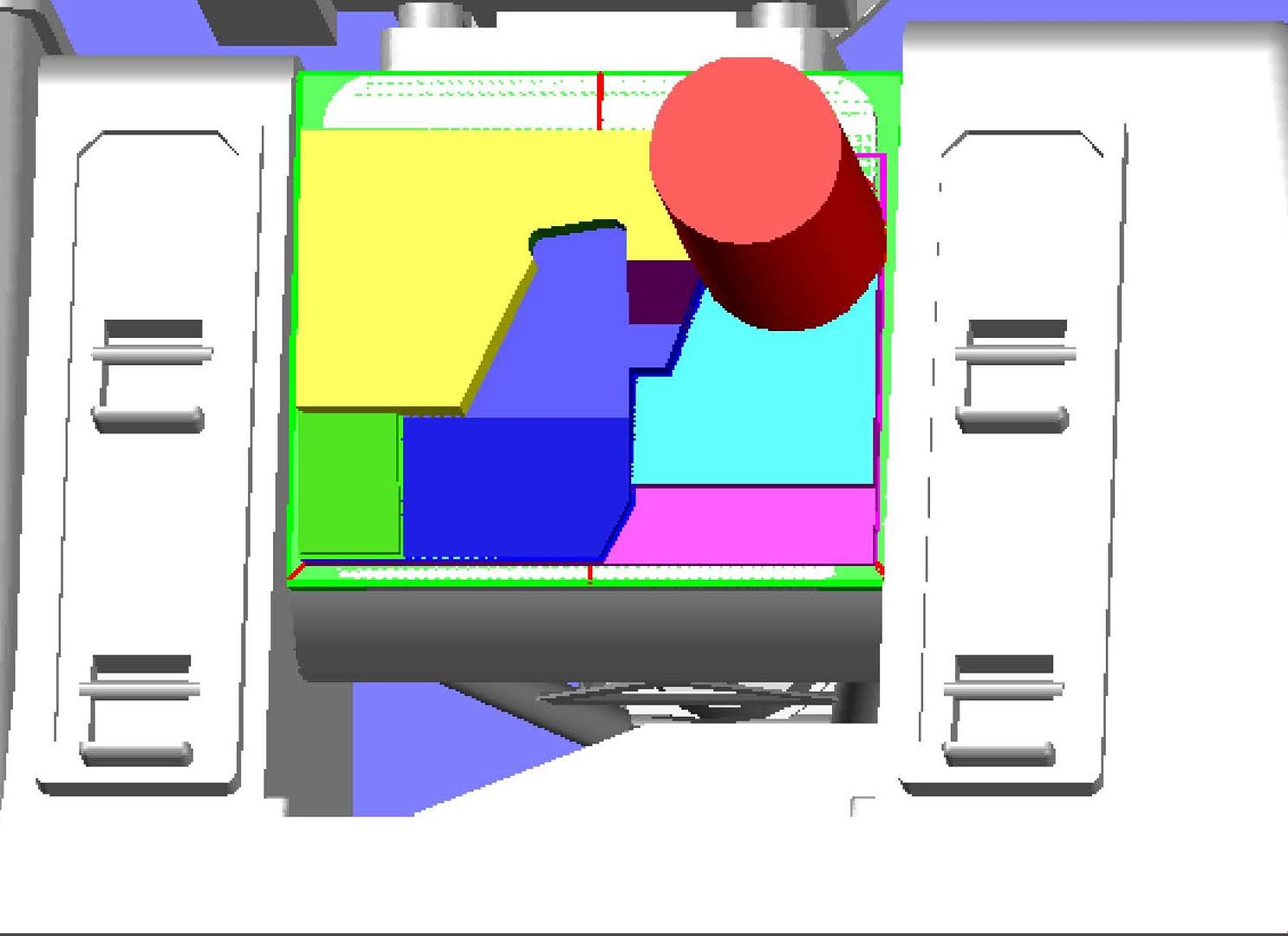 I then filleted all of the edges… 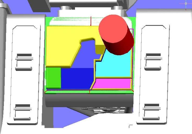 …And although I failed to document it, I added the visor on the top. 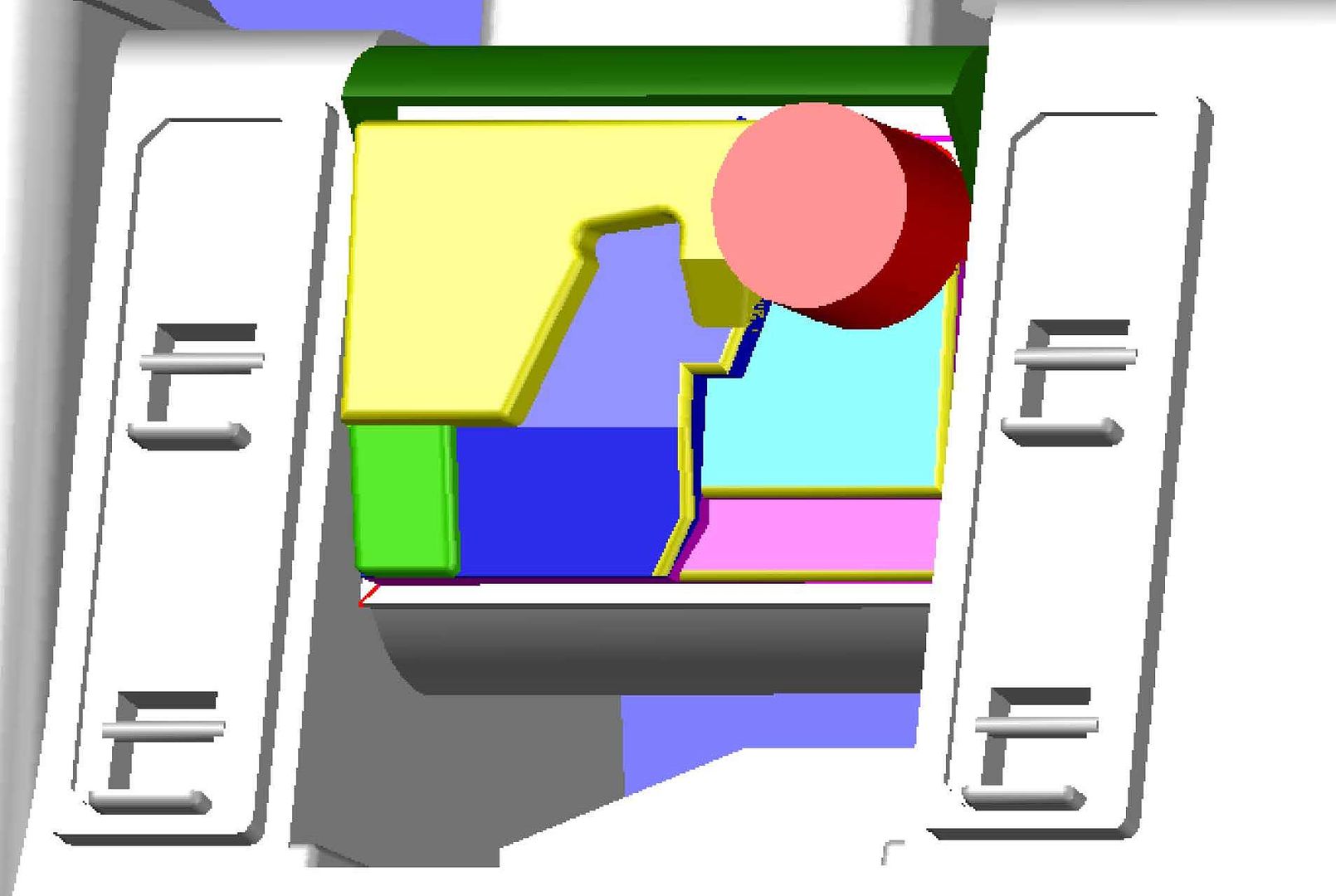 At this point I colored it all gray and turned my attention to the exhaust vent. I started by drawing a circle 0.1 mm less in diameter than the original, extruding it… 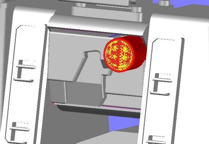 …And subtracting it leaving walls that are 0.05 mm thick. 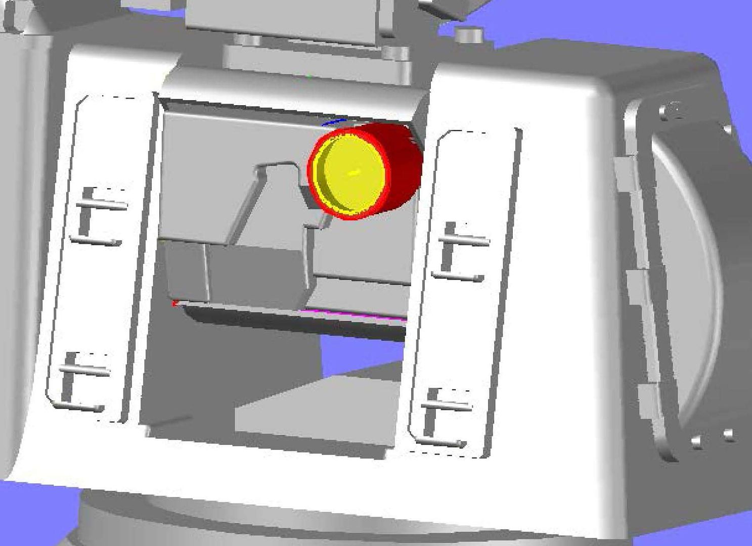 To make the vent slats, I extruded a 0.05 mm thick rectangle flush with the outside edge of the vent through the pipe. 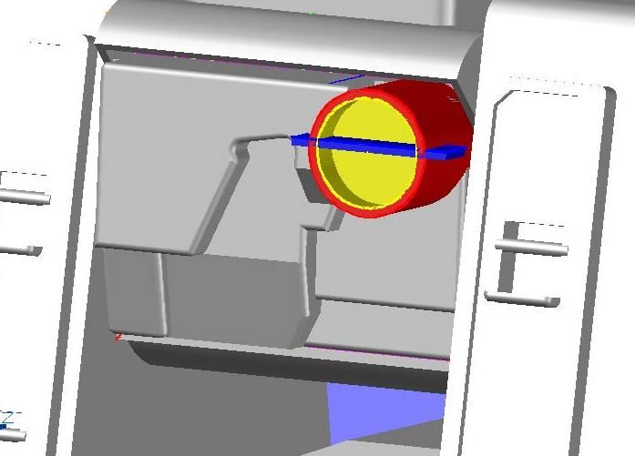 The slats aren’t straight though, so I rotated it until I thought it looked right. 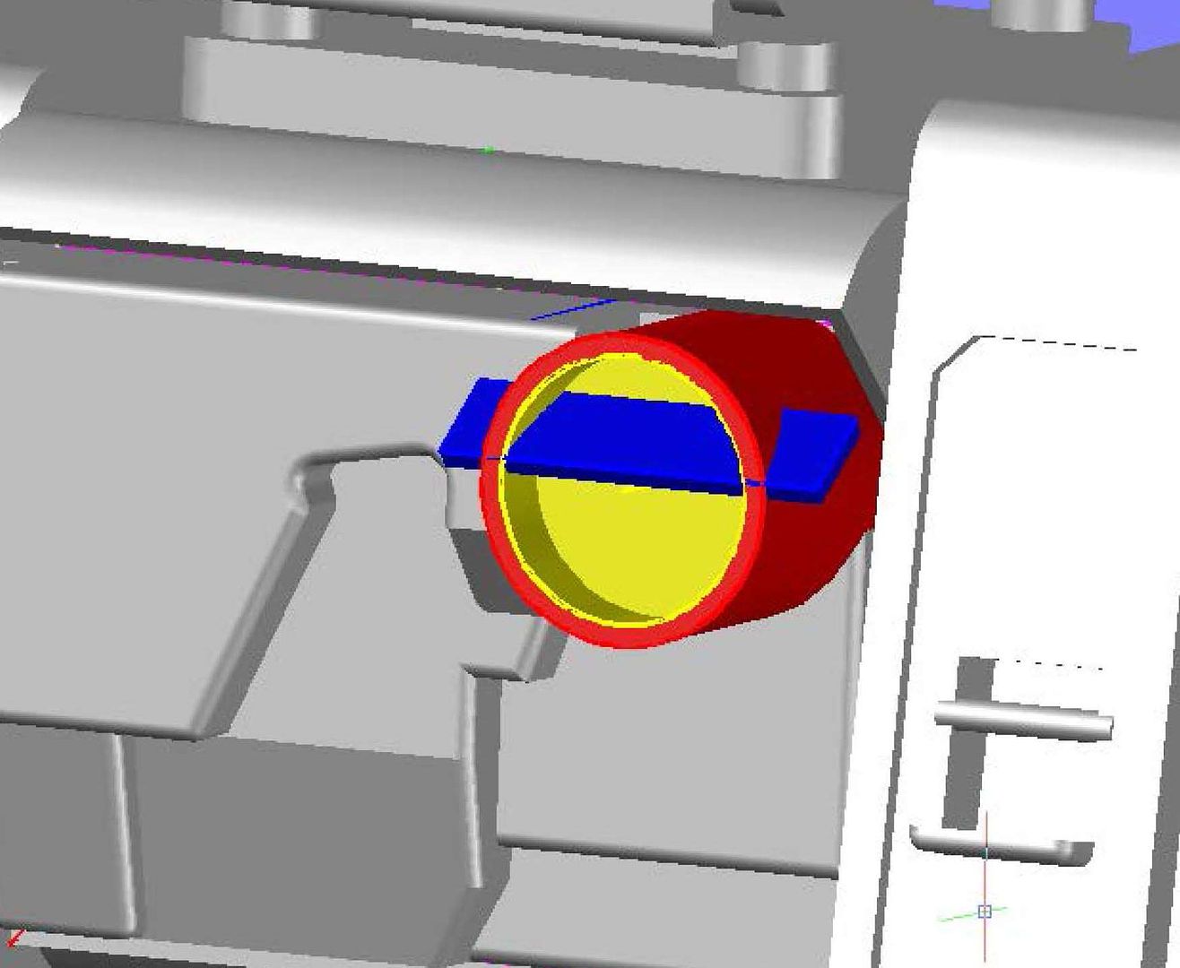 The picture shows 5 slats so I arrayed them to look like the picture. 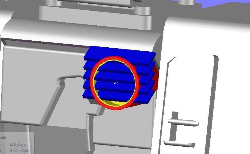 Next, I lofted a circle with the ID diameter of the pipe… 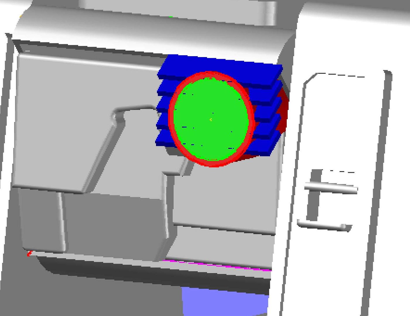 …And used the intersect command to remove the parts I didn’t want, leaving a pretty nice vent. 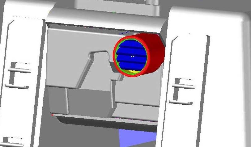 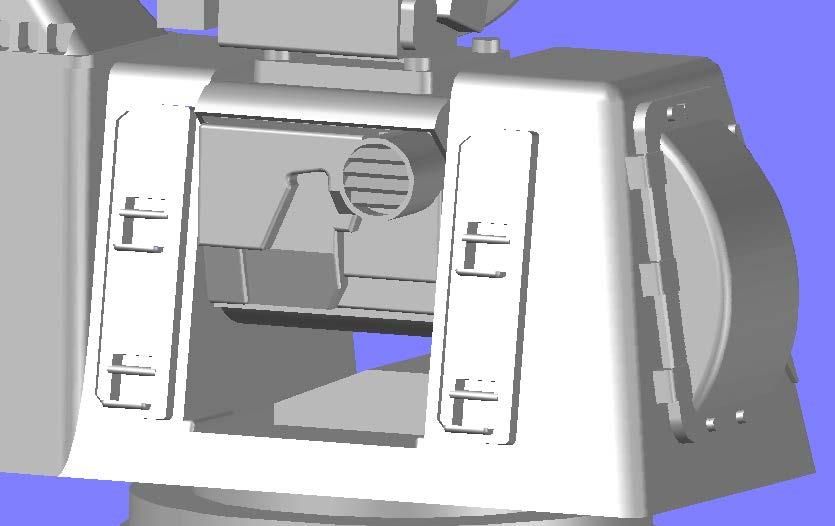 With the back of the barrel completed, I added a block on top to somewhat replicate the picture, although there was enough deviation between the line drawings and what I can decipher from the pictures I have that I can’t match it exactly without a major overhaul, which isn’t really justified by this small detail. 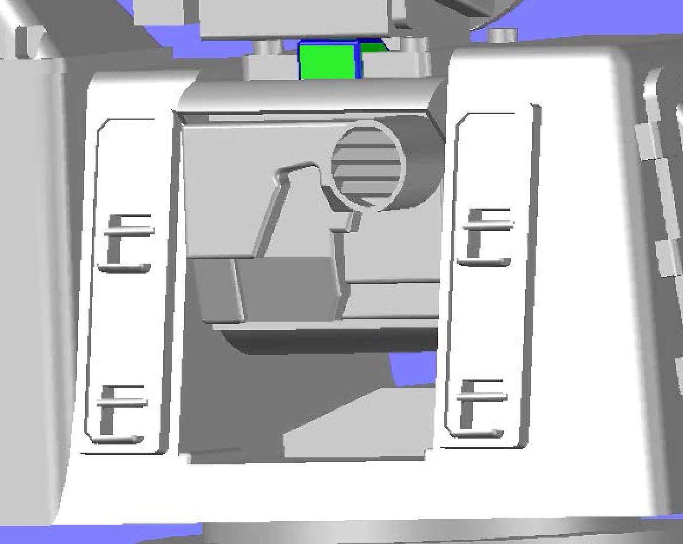 Next, I turned my attention to the variable diameter shaft, starting with the middle one, which I extruded to the left end of the shaft and sliced even with the back face of the barrel frame (at the bottom of the lower level). 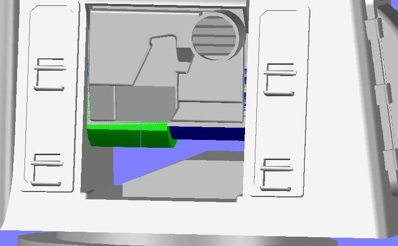 This was followed by the left most part of the shaft, which is considerably larger. The extruded circle was sliced even with the top of the second level, and also with the front edge of the barrel support (not shown). 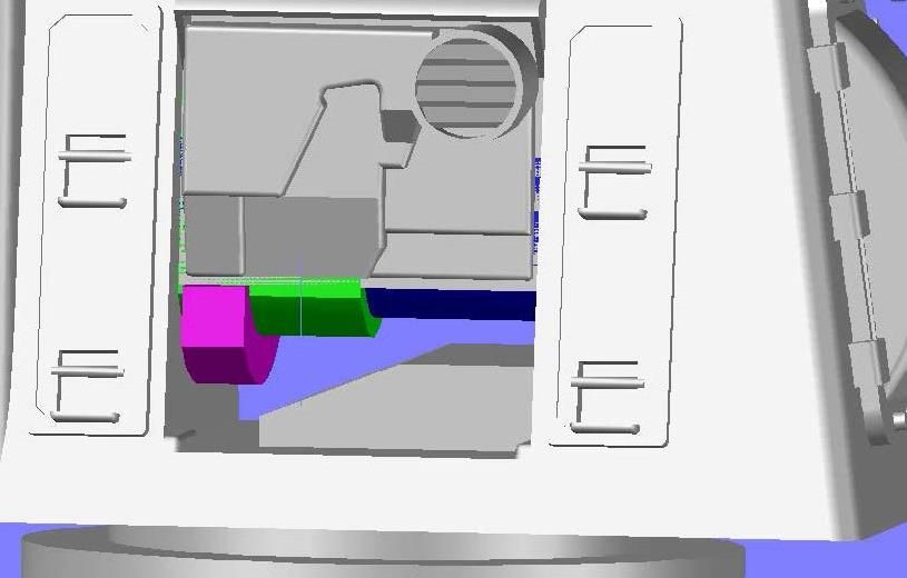 I colored it and the first stage of this journey came to an end. 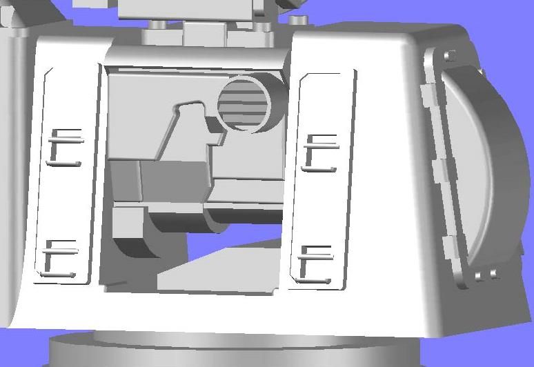 Stay tuned for more images of the completed Goalkeeper, and a little surprise.
[u][b]UPDATE 13[/b][/u]
Hi guys!
I got on a roll last night and completed the Goalkeeper, or I should say that I completed the first draft of it. I could have missed something, or done something wrong, or perhaps get pictures to better show a couple of areas that I adlibbed due to lack of good images of them. The grabs on the front and the wing nuts on the side come to mind.
Anyway, here is the rest of the build. It’s quite a long post, so sit back and enjoy.
Here is the way the back looked based on the line drawings I used.
[url=http://s1352.photobucket.com/user/rdutnell/media/Goalkeeper/pix13_Page_01_zps2999fedc.jpg.html][img]http://i1352.photobucket.com/albums/q659/rdutnell/Goalkeeper/pix13_Page_01_zps2999fedc.jpg[/img][/url]
The first thing I noticed is that the barrel was too low, so I moved it up.
[url=http://s1352.photobucket.com/user/rdutnell/media/Goalkeeper/pix13_Page_02_zps3c202e68.jpg.html][img]http://i1352.photobucket.com/albums/q659/rdutnell/Goalkeeper/pix13_Page_02_zps3c202e68.jpg[/img][/url]
The next thing I did was slice the back of the barrel off even with the back edge of the top plate.
[url=http://s1352.photobucket.com/user/rdutnell/media/Goalkeeper/pix13_Page_03_zps5ede2292.jpg.html][img]http://i1352.photobucket.com/albums/q659/rdutnell/Goalkeeper/pix13_Page_03_zps5ede2292.jpg[/img][/url]
Also, the barrel seemed too thin, so I widened it. Well, I didn’t actually widen it, I made a new one with the same height, but wider.
[url=http://s1352.photobucket.com/user/rdutnell/media/Goalkeeper/pix13_Page_05_zps4c692f97.jpg.html][img]http://i1352.photobucket.com/albums/q659/rdutnell/Goalkeeper/pix13_Page_05_zps4c692f97.jpg[/img][/url]
I also sliced off the shaft.
[url=http://s1352.photobucket.com/user/rdutnell/media/Goalkeeper/pix13_Page_06_zpsdaebbbde.jpg.html][img]http://i1352.photobucket.com/albums/q659/rdutnell/Goalkeeper/pix13_Page_06_zpsdaebbbde.jpg[/img][/url]
I built the back up in layers, with the exception of the exhaust tube on the upper right, which I drew first, followed by the outline of the first level.
[url=http://s1352.photobucket.com/user/rdutnell/media/Goalkeeper/pix13_Page_07_zpsdd44c01b.jpg.html][img]http://i1352.photobucket.com/albums/q659/rdutnell/Goalkeeper/pix13_Page_07_zpsdd44c01b.jpg[/img][/url]
I then extruded the first level…
[url=http://s1352.photobucket.com/user/rdutnell/media/Goalkeeper/pix13_Page_08_zps32f1dcbc.jpg.html][img]http://i1352.photobucket.com/albums/q659/rdutnell/Goalkeeper/pix13_Page_08_zps32f1dcbc.jpg[/img][/url]
The upper right corner of the first level follows the outline of the exhaust tube, so I filleted the edge to match.
[url=http://s1352.photobucket.com/user/rdutnell/media/Goalkeeper/pix13_Page_09_zps86316dbc.jpg.html][img]http://i1352.photobucket.com/albums/q659/rdutnell/Goalkeeper/pix13_Page_09_zps86316dbc.jpg[/img][/url]
The first level actually has a notch cut in the bottom right corner, so I cut it out to match the photo.
[url=http://s1352.photobucket.com/user/rdutnell/media/Goalkeeper/pix13_Page_10_zpsd55d3f1d.jpg.html][img]http://i1352.photobucket.com/albums/q659/rdutnell/Goalkeeper/pix13_Page_10_zpsd55d3f1d.jpg[/img][/url]
Next, I traced out the outline of the second level and extruded it. As I was doing this I realized that the exhaust vent was too small so I made it larger.
[url=http://s1352.photobucket.com/user/rdutnell/media/Goalkeeper/pix13_Page_11_zps4ab000f2.jpg.html][img]http://i1352.photobucket.com/albums/q659/rdutnell/Goalkeeper/pix13_Page_11_zps4ab000f2.jpg[/img][/url]
The lower part of the second level is sloped, so I sliced off the end.
[url=http://s1352.photobucket.com/user/rdutnell/media/Goalkeeper/pix13_Page_12_zps714a6bea.jpg.html][img]http://i1352.photobucket.com/albums/q659/rdutnell/Goalkeeper/pix13_Page_12_zps714a6bea.jpg[/img][/url]
About this time I realized that my layers were too thick, so I sliced them thinner.
[url=http://s1352.photobucket.com/user/rdutnell/media/Goalkeeper/pix13_Page_13_zpse75e7164.jpg.html][img]http://i1352.photobucket.com/albums/q659/rdutnell/Goalkeeper/pix13_Page_13_zpse75e7164.jpg[/img][/url]
The last level was the most difficult to do, but I started by extruding the outline shown below in yellow.
[url=http://s1352.photobucket.com/user/rdutnell/media/Goalkeeper/pix13_Page_14_zps0661c138.jpg.html][img]http://i1352.photobucket.com/albums/q659/rdutnell/Goalkeeper/pix13_Page_14_zps0661c138.jpg[/img][/url]
A section on the lower right of the top level slopes down to the second level, so I prepared to do this by drawing a properly sized rectangle at the top of the slope and copied it down to the location of the bottom of the slope…
[url=http://s1352.photobucket.com/user/rdutnell/media/Goalkeeper/pix13_Page_15_zps26fda183.jpg.html][img]http://i1352.photobucket.com/albums/q659/rdutnell/Goalkeeper/pix13_Page_15_zps26fda183.jpg[/img][/url]
…Moved the lower one into the lower level and lofted them.
[url=http://s1352.photobucket.com/user/rdutnell/media/Goalkeeper/pix13_Page_16_zps16e8b8cb.jpg.html][img]http://i1352.photobucket.com/albums/q659/rdutnell/Goalkeeper/pix13_Page_16_zps16e8b8cb.jpg[/img][/url]
The top level also has a cutout at the top. I created this by drawing a polygon, filleting the corners, extruding the shape…
[url=http://s1352.photobucket.com/user/rdutnell/media/Goalkeeper/pix13_Page_17_zpsc17f2375.jpg.html][img]http://i1352.photobucket.com/albums/q659/rdutnell/Goalkeeper/pix13_Page_17_zpsc17f2375.jpg[/img][/url]
…And subtracting it.
[url=http://s1352.photobucket.com/user/rdutnell/media/Goalkeeper/pix13_Page_18_zps4b98bff6.jpg.html][img]http://i1352.photobucket.com/albums/q659/rdutnell/Goalkeeper/pix13_Page_18_zps4b98bff6.jpg[/img][/url]
In the bottom left hand corner, there is a plate that extrudes up from the second level, but not all the way up to the third level. It is sloped like the lower part of the second level. Once I got the coordinate system lined up properly this was easily done by drawing a rectangle on the face of the slope and extruding it up.
[url=http://s1352.photobucket.com/user/rdutnell/media/Goalkeeper/pix13_Page_19_zps51c1b754.jpg.html][img]http://i1352.photobucket.com/albums/q659/rdutnell/Goalkeeper/pix13_Page_19_zps51c1b754.jpg[/img][/url]
I then filleted all of the edges…
[url=http://s1352.photobucket.com/user/rdutnell/media/Goalkeeper/pix13_Page_20_zpsd8c25daf.jpg.html][img]http://i1352.photobucket.com/albums/q659/rdutnell/Goalkeeper/pix13_Page_20_zpsd8c25daf.jpg[/img][/url]
…And although I failed to document it, I added the visor on the top.
[url=http://s1352.photobucket.com/user/rdutnell/media/Goalkeeper/pix13_Page_21_zps11ac3c4d.jpg.html][img]http://i1352.photobucket.com/albums/q659/rdutnell/Goalkeeper/pix13_Page_21_zps11ac3c4d.jpg[/img][/url]
At this point I colored it all gray and turned my attention to the exhaust vent. I started by drawing a circle 0.1 mm less in diameter than the original, extruding it…
[url=http://s1352.photobucket.com/user/rdutnell/media/Goalkeeper/pix13_Page_22_zps696d5b5a.jpg.html][img]http://i1352.photobucket.com/albums/q659/rdutnell/Goalkeeper/pix13_Page_22_zps696d5b5a.jpg[/img][/url]
…And subtracting it leaving walls that are 0.05 mm thick.
[url=http://s1352.photobucket.com/user/rdutnell/media/Goalkeeper/pix13_Page_23_zps7a35e8fd.jpg.html][img]http://i1352.photobucket.com/albums/q659/rdutnell/Goalkeeper/pix13_Page_23_zps7a35e8fd.jpg[/img][/url]
To make the vent slats, I extruded a 0.05 mm thick rectangle flush with the outside edge of the vent through the pipe.
[url=http://s1352.photobucket.com/user/rdutnell/media/Goalkeeper/pix13_Page_24_zps1c3e7185.jpg.html][img]http://i1352.photobucket.com/albums/q659/rdutnell/Goalkeeper/pix13_Page_24_zps1c3e7185.jpg[/img][/url]
The slats aren’t straight though, so I rotated it until I thought it looked right.
[url=http://s1352.photobucket.com/user/rdutnell/media/Goalkeeper/pix13_Page_25_zps09ab152f.jpg.html][img]http://i1352.photobucket.com/albums/q659/rdutnell/Goalkeeper/pix13_Page_25_zps09ab152f.jpg[/img][/url]
The picture shows 5 slats so I arrayed them to look like the picture.
[url=http://s1352.photobucket.com/user/rdutnell/media/Goalkeeper/pix13_Page_26_zpsdd587b33.jpg.html][img]http://i1352.photobucket.com/albums/q659/rdutnell/Goalkeeper/pix13_Page_26_zpsdd587b33.jpg[/img][/url]
Next, I lofted a circle with the ID diameter of the pipe…
[url=http://s1352.photobucket.com/user/rdutnell/media/Goalkeeper/pix13_Page_27_zps79d741e3.jpg.html][img]http://i1352.photobucket.com/albums/q659/rdutnell/Goalkeeper/pix13_Page_27_zps79d741e3.jpg[/img][/url]
…And used the intersect command to remove the parts I didn’t want, leaving a pretty nice vent.
[url=http://s1352.photobucket.com/user/rdutnell/media/Goalkeeper/pix13_Page_28_zpse4a36fcd.jpg.html][img]http://i1352.photobucket.com/albums/q659/rdutnell/Goalkeeper/pix13_Page_28_zpse4a36fcd.jpg[/img][/url]
[url=http://s1352.photobucket.com/user/rdutnell/media/Goalkeeper/pix13_Page_29_zps13293a67.jpg.html][img]http://i1352.photobucket.com/albums/q659/rdutnell/Goalkeeper/pix13_Page_29_zps13293a67.jpg[/img][/url]
With the back of the barrel completed, I added a block on top to somewhat replicate the picture, although there was enough deviation between the line drawings and what I can decipher from the pictures I have that I can’t match it exactly without a major overhaul, which isn’t really justified by this small detail.
[url=http://s1352.photobucket.com/user/rdutnell/media/Goalkeeper/pix13_Page_30_zps6f6a6b46.jpg.html][img]http://i1352.photobucket.com/albums/q659/rdutnell/Goalkeeper/pix13_Page_30_zps6f6a6b46.jpg[/img][/url]
Next, I turned my attention to the variable diameter shaft, starting with the middle one, which I extruded to the left end of the shaft and sliced even with the back face of the barrel frame (at the bottom of the lower level).
[url=http://s1352.photobucket.com/user/rdutnell/media/Goalkeeper/pix13_Page_31_zps88e8fb1c.jpg.html][img]http://i1352.photobucket.com/albums/q659/rdutnell/Goalkeeper/pix13_Page_31_zps88e8fb1c.jpg[/img][/url]
This was followed by the left most part of the shaft, which is considerably larger. The extruded circle was sliced even with the top of the second level, and also with the front edge of the barrel support (not shown).
[url=http://s1352.photobucket.com/user/rdutnell/media/Goalkeeper/pix13_Page_32_zpsb581549c.jpg.html][img]http://i1352.photobucket.com/albums/q659/rdutnell/Goalkeeper/pix13_Page_32_zpsb581549c.jpg[/img][/url]
I colored it and the first stage of this journey came to an end.
[url=http://s1352.photobucket.com/user/rdutnell/media/Goalkeeper/pix13_Page_33_zps01f0eac4.jpg.html][img]http://i1352.photobucket.com/albums/q659/rdutnell/Goalkeeper/pix13_Page_33_zps01f0eac4.jpg[/img][/url]
Stay tuned for more images of the completed Goalkeeper, and a little surprise.
|
|
|
|
Posted: Mon Jun 03, 2013 11:04 am |
|
|
|
|
|
| |
Post subject: |
Re: 1/350 Goalkeeper close-in weapon system (CIWS) in AutoCa |
|
|
UPDATE 12Hi Swordfish, I’m glad to hear that you have been enjoying the post. The only CAD program I have ever used is AutoCad, or its variations. I have never used 3Ds Max and have no idea what you mean by the Patch method. It sounds like you should build either SSN-579 or SS-193, your namesakes.  ) Here is some more progress on the Goalkeeper for your viewing pleasure. Before moving to the aft end of the gun barrel, I decided to have a go at the cage on the upper right side of the antenna arm. I started by drawing a rectangle in the proper position, rounding the edges and extruding it. I then sliced the top off and prepared to draw the tubing for the cage. 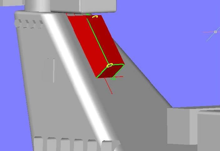 The cage tubing was made using 0.04 mm radius circles, which again, I understand the 3d Printer can print, but may be too delicate to include in the final product. I guess we will see. 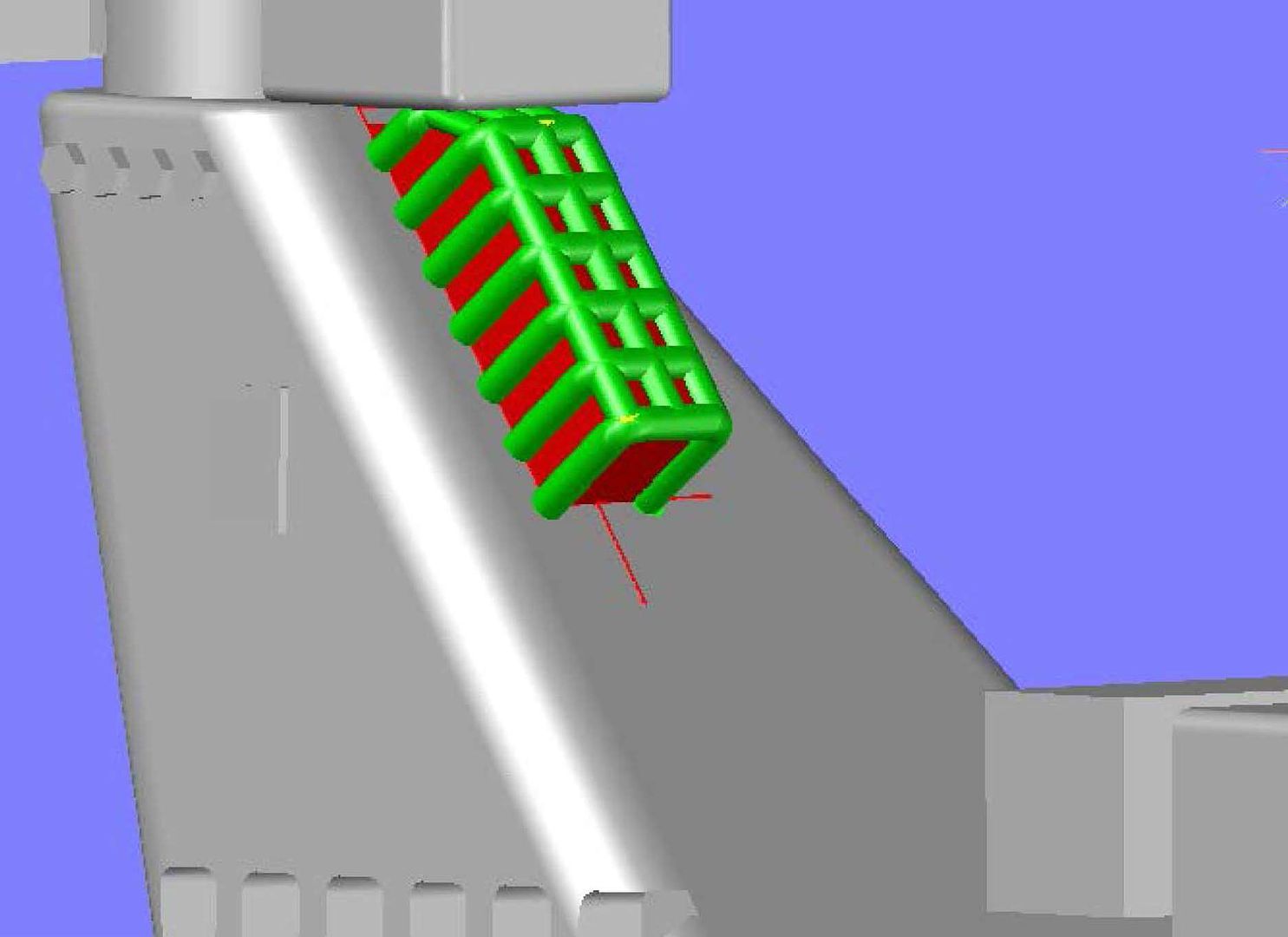 I then deleted the cage template, for lack of a better name for it… 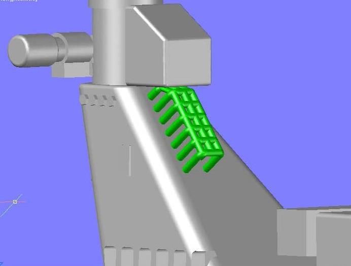 …And recolored it gray. 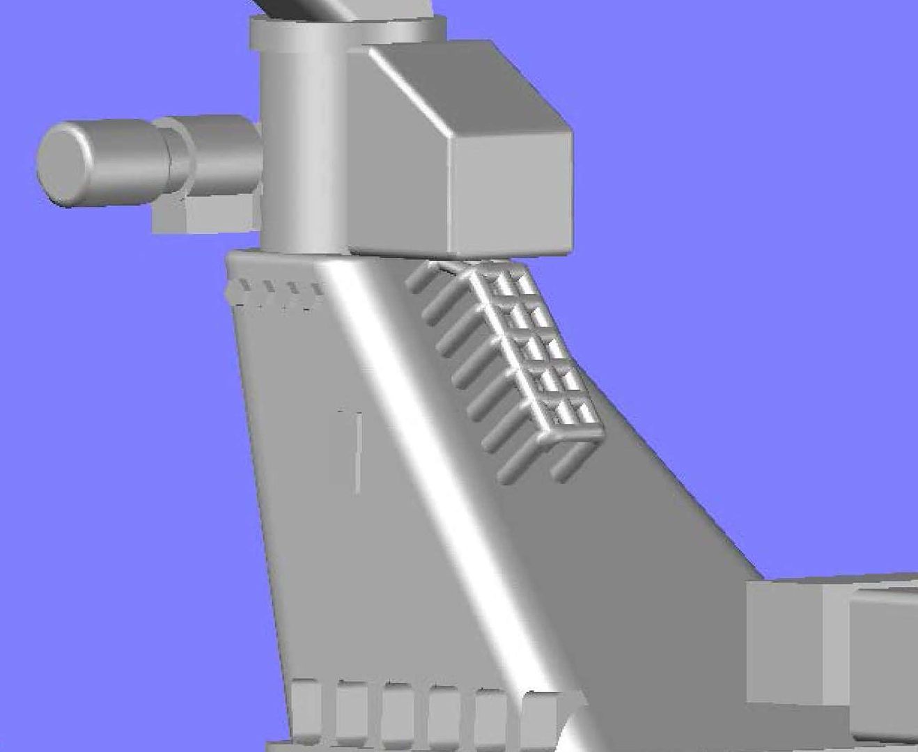 Next, I started on the grab seen on the arm, by first copying one of the grabs from the front face over to the side. 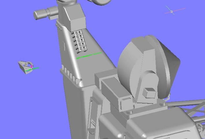 The grab is out of alignment in both planes, so first I rotated it so the long side was in the proper orientation. 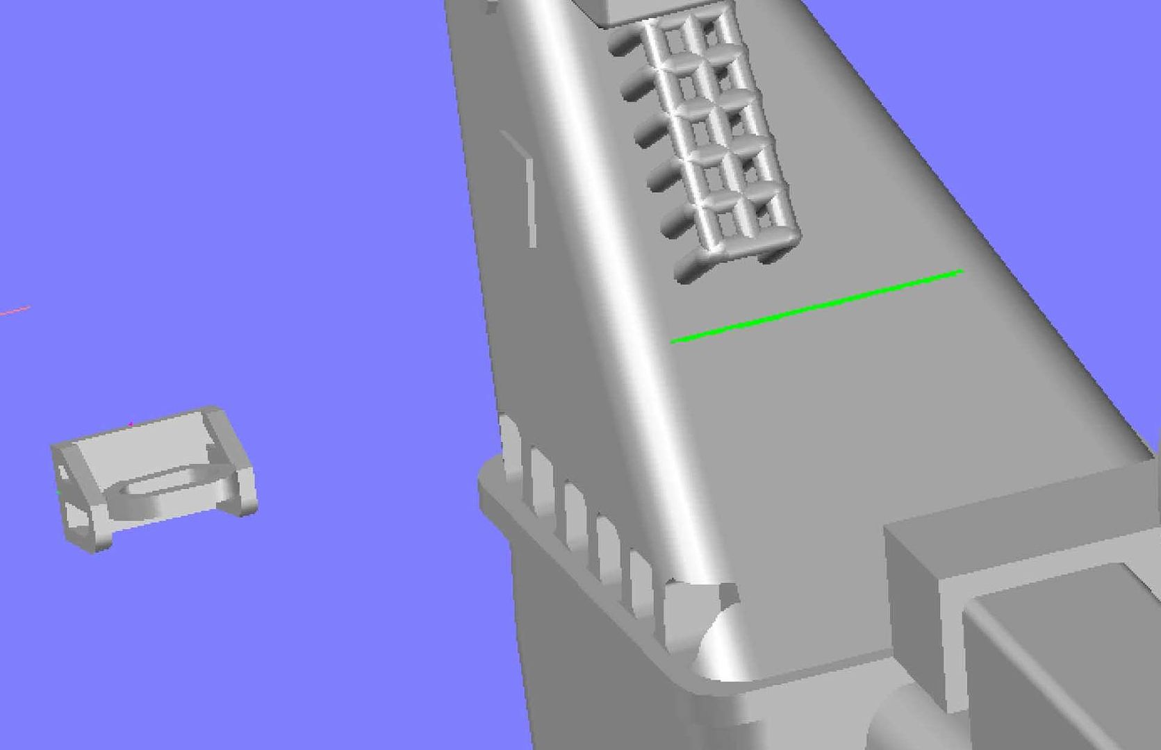 I then moved it to the center of the arm. 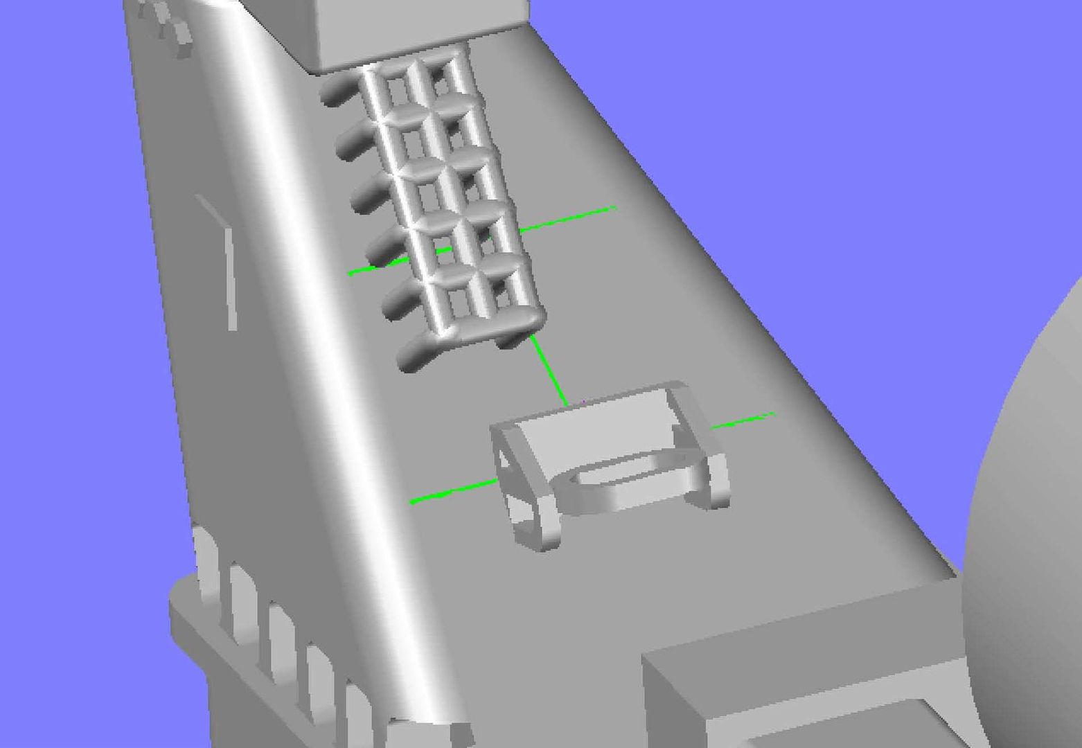 You can see in the image below that it still needed to be rotated to be flush with the face… 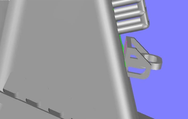 …So I rotated it. 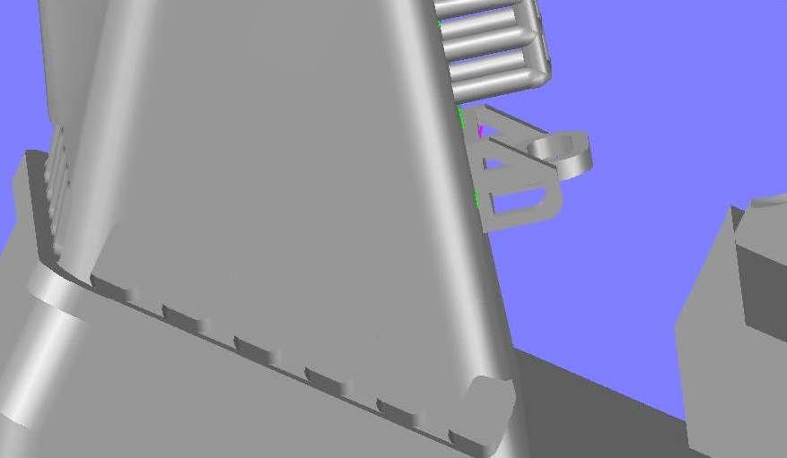 The grab is not located in the center, so I moved it to the left to match where it appears to be in pictures, and rotated t he grab itself so that it was level.  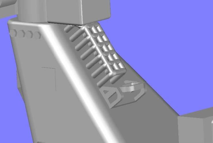 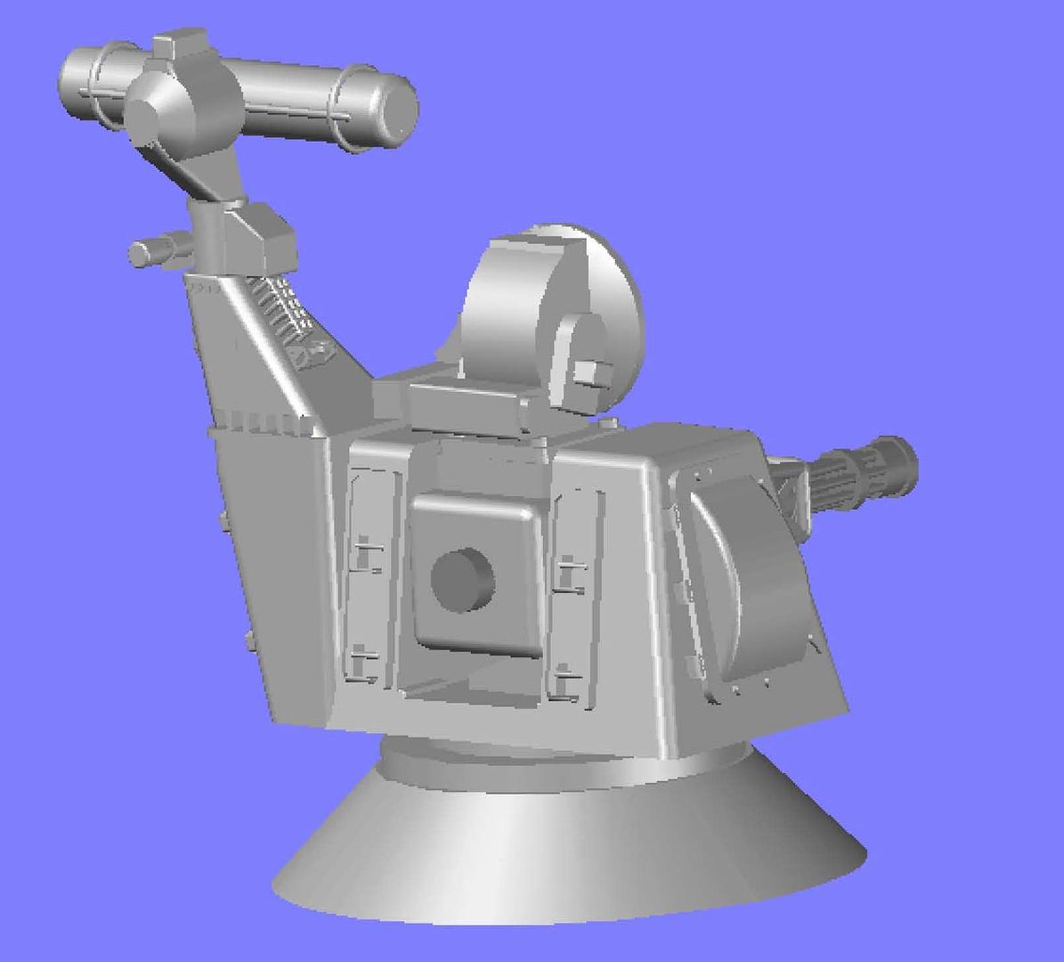 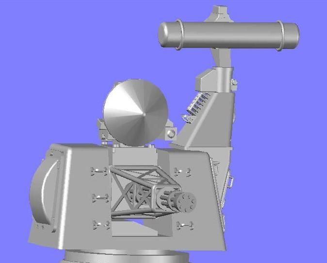 Now to the back of the gun.
[u][b]UPDATE 12[/b][/u]
Hi Swordfish,
I’m glad to hear that you have been enjoying the post. The only CAD program I have ever used is AutoCad, or its variations. I have never used 3Ds Max and have no idea what you mean by the Patch method. It sounds like you should build either SSN-579 or SS-193, your namesakes. :o) Here is some more progress on the Goalkeeper for your viewing pleasure.
Before moving to the aft end of the gun barrel, I decided to have a go at the cage on the upper right side of the antenna arm. I started by drawing a rectangle in the proper position, rounding the edges and extruding it. I then sliced the top off and prepared to draw the tubing for the cage.
[url=http://s1352.photobucket.com/user/rdutnell/media/Goalkeeper/pix12_Page_01_zps1c23f627.jpg.html][img]http://i1352.photobucket.com/albums/q659/rdutnell/Goalkeeper/pix12_Page_01_zps1c23f627.jpg[/img][/url]
The cage tubing was made using 0.04 mm radius circles, which again, I understand the 3d Printer can print, but may be too delicate to include in the final product. I guess we will see.
[url=http://s1352.photobucket.com/user/rdutnell/media/Goalkeeper/pix12_Page_02_zps9ecdabc5.jpg.html][img]http://i1352.photobucket.com/albums/q659/rdutnell/Goalkeeper/pix12_Page_02_zps9ecdabc5.jpg[/img][/url]
I then deleted the cage template, for lack of a better name for it…
[url=http://s1352.photobucket.com/user/rdutnell/media/Goalkeeper/pix12_Page_03_zps6756fc86.jpg.html][img]http://i1352.photobucket.com/albums/q659/rdutnell/Goalkeeper/pix12_Page_03_zps6756fc86.jpg[/img][/url]
…And recolored it gray.
[url=http://s1352.photobucket.com/user/rdutnell/media/Goalkeeper/pix12_Page_04_zps14e5d0b4.jpg.html][img]http://i1352.photobucket.com/albums/q659/rdutnell/Goalkeeper/pix12_Page_04_zps14e5d0b4.jpg[/img][/url]
Next, I started on the grab seen on the arm, by first copying one of the grabs from the front face over to the side.
[url=http://s1352.photobucket.com/user/rdutnell/media/Goalkeeper/pix12_Page_05_zpse6923854.jpg.html][img]http://i1352.photobucket.com/albums/q659/rdutnell/Goalkeeper/pix12_Page_05_zpse6923854.jpg[/img][/url]
The grab is out of alignment in both planes, so first I rotated it so the long side was in the proper orientation.
[url=http://s1352.photobucket.com/user/rdutnell/media/Goalkeeper/pix12_Page_06_zps803e8cd6.jpg.html][img]http://i1352.photobucket.com/albums/q659/rdutnell/Goalkeeper/pix12_Page_06_zps803e8cd6.jpg[/img][/url]
I then moved it to the center of the arm.
[url=http://s1352.photobucket.com/user/rdutnell/media/Goalkeeper/pix12_Page_07_zpsee61dfa8.jpg.html][img]http://i1352.photobucket.com/albums/q659/rdutnell/Goalkeeper/pix12_Page_07_zpsee61dfa8.jpg[/img][/url]
You can see in the image below that it still needed to be rotated to be flush with the face…
[url=http://s1352.photobucket.com/user/rdutnell/media/Goalkeeper/pix12_Page_08_zps1f927a7e.jpg.html][img]http://i1352.photobucket.com/albums/q659/rdutnell/Goalkeeper/pix12_Page_08_zps1f927a7e.jpg[/img][/url]
…So I rotated it.
[url=http://s1352.photobucket.com/user/rdutnell/media/Goalkeeper/pix12_Page_09_zps6d9b6c34.jpg.html][img]http://i1352.photobucket.com/albums/q659/rdutnell/Goalkeeper/pix12_Page_09_zps6d9b6c34.jpg[/img][/url]
The grab is not located in the center, so I moved it to the left to match where it appears to be in pictures, and rotated t he grab itself so that it was level.
[url=http://s1352.photobucket.com/user/rdutnell/media/Goalkeeper/pix12_Page_10_zpsb3901ae9.jpg.html][img]http://i1352.photobucket.com/albums/q659/rdutnell/Goalkeeper/pix12_Page_10_zpsb3901ae9.jpg[/img][/url]
[url=http://s1352.photobucket.com/user/rdutnell/media/Goalkeeper/pix12_Page_11_zpsc126903a.jpg.html][img]http://i1352.photobucket.com/albums/q659/rdutnell/Goalkeeper/pix12_Page_11_zpsc126903a.jpg[/img][/url]
[url=http://s1352.photobucket.com/user/rdutnell/media/Goalkeeper/pix12_Page_12_zps6482448a.jpg.html][img]http://i1352.photobucket.com/albums/q659/rdutnell/Goalkeeper/pix12_Page_12_zps6482448a.jpg[/img][/url]
[url=http://s1352.photobucket.com/user/rdutnell/media/Goalkeeper/pix12_Page_13_zpsaebf3ea1.jpg.html][img]http://i1352.photobucket.com/albums/q659/rdutnell/Goalkeeper/pix12_Page_13_zpsaebf3ea1.jpg[/img][/url]
Now to the back of the gun.
|
|
|
|
Posted: Sun Jun 02, 2013 9:55 pm |
|
|
|
|
|
| |
Post subject: |
Re: 1/350 Goalkeeper close-in weapon system (CIWS) in AutoCa |
|
|
|
Very cool to see the project in CAD. I personally use 3Ds Max, so although different, I see how it comes together. I use the Patch method, it has been about 3-4 years since I have tinkered with the program but I just got my hands on it again and I think ill try my hand at something there before building my first real life model.
-swordfish
|
|
|
|
Posted: Sun Jun 02, 2013 6:52 pm |
|
|
|
|
|
| |
Post subject: |
Re: 1/350 Goalkeeper close-in weapon system (CIWS) in AutoCa |
|
|
UPDATE 11With the grabs finished (for now) I moved to the right side. The first thing I noticed was that I had not added the box to the radar support arm, so I added it. By extruding a rectangle and rounding the edges. 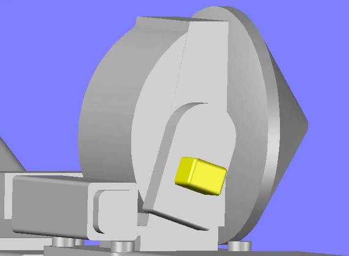 Next I prepared for the large rounded object on the side of the main body. 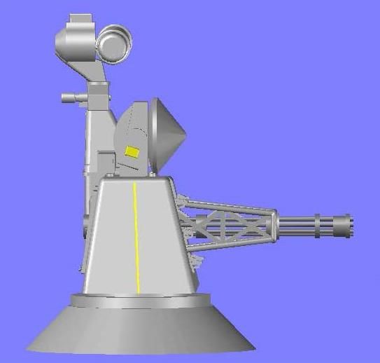 I first drew the outline of the outer plate. 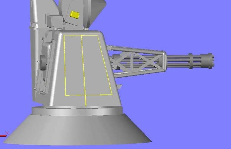 I extruded it into the side, and then rounded the corners. For the main body, I joined an arc and line to form a polyline that I then extruded, and rounded the edges of the extrusion. 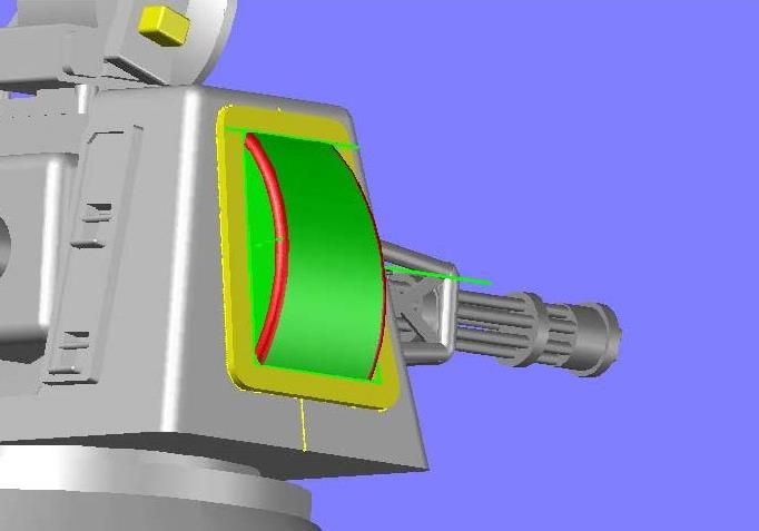 The rest of it was pretty much made up because I can’t really tell from the photos I have what the detailing on the side is. It almost looks like hinges on the left, so I used extruded rectangles to make them. 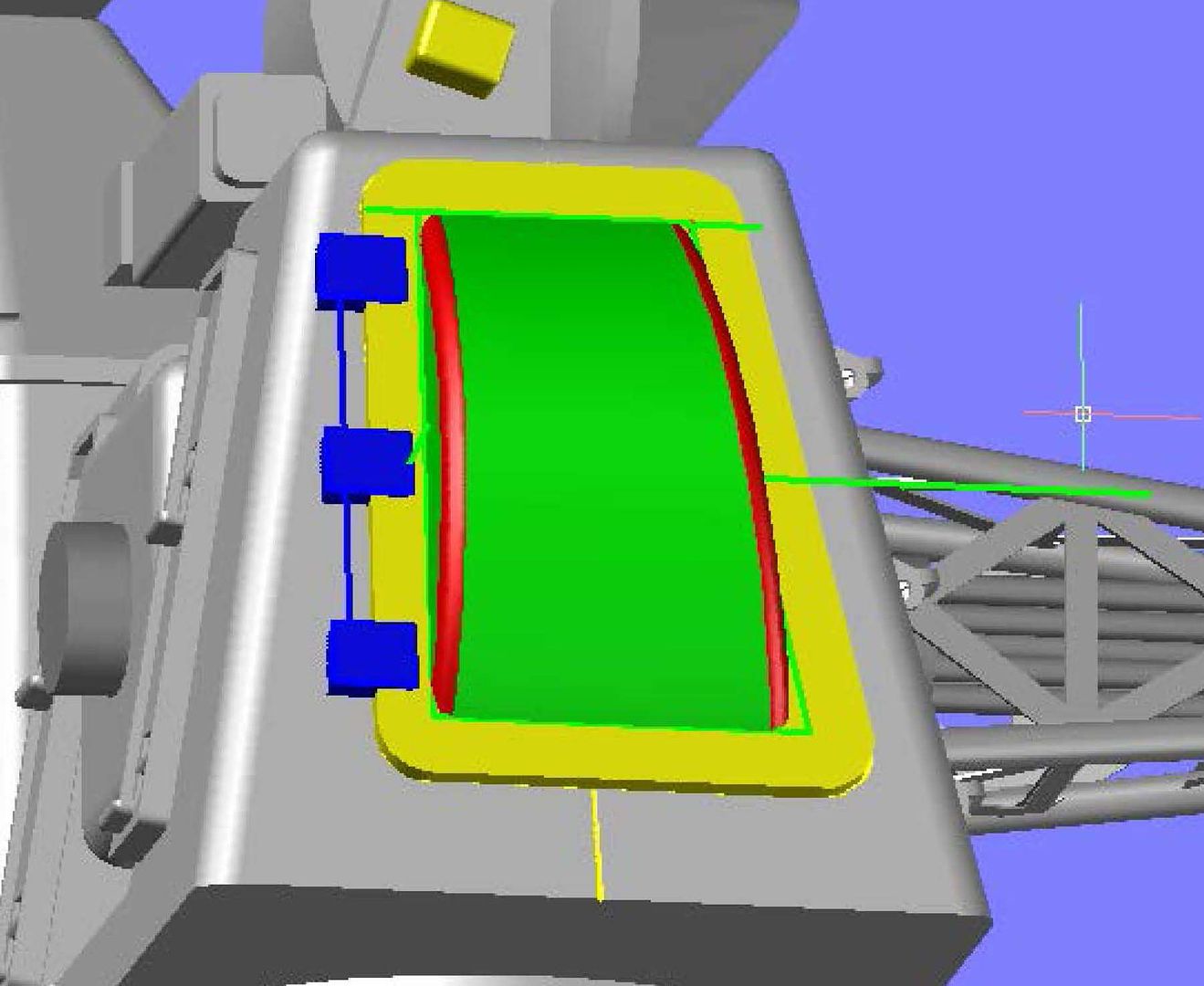 I also can’t tell what the objects around the bottom and right side. They appear to be some sort of tightening lever, or possibly a type of wing nut. In any case I winged them. 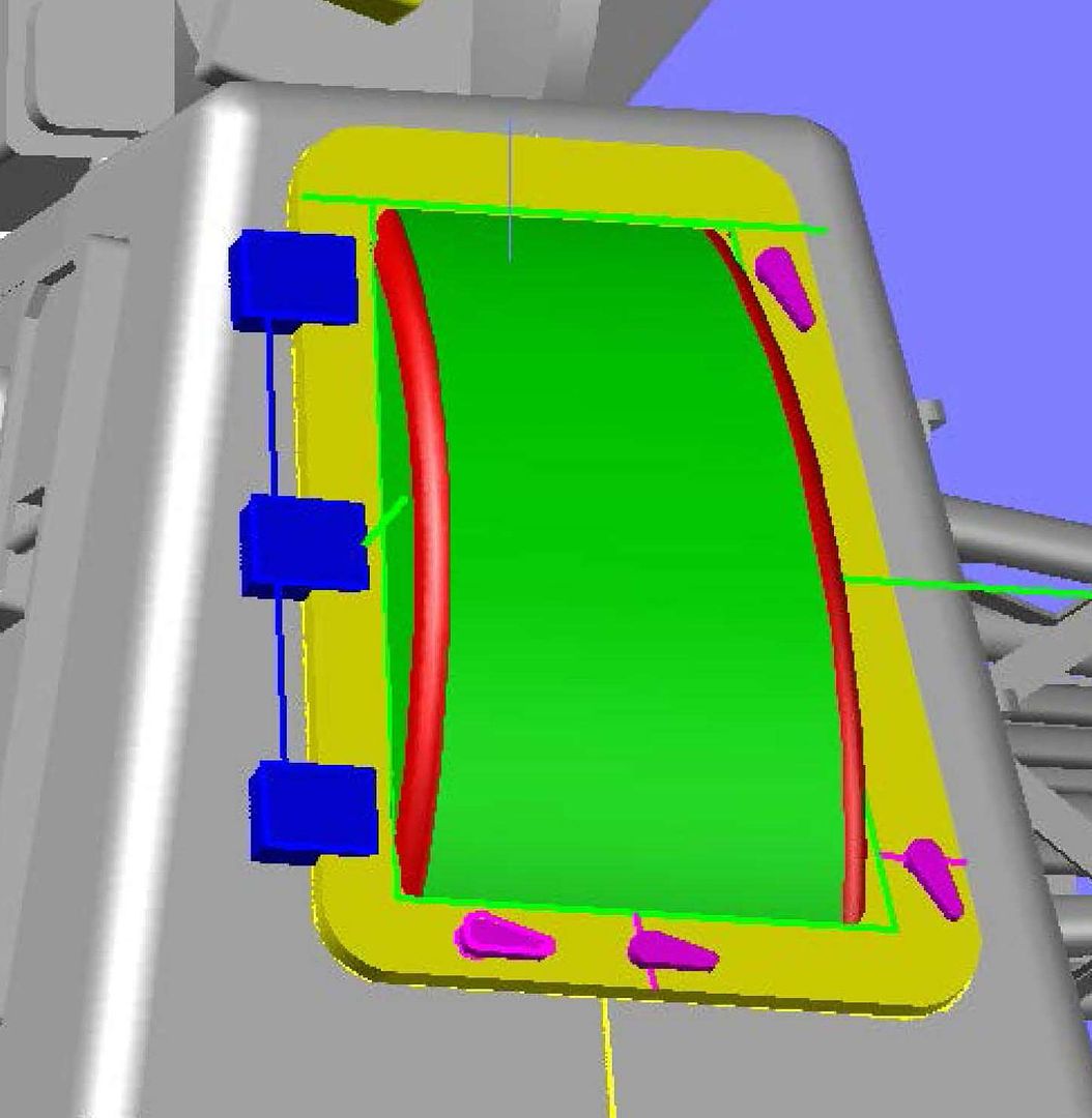 I had a pretty good picture of the object at the top that appears to be a relieve valve of some sort. I matched it as close as possible without getting below 0.04 mm in any dimension. 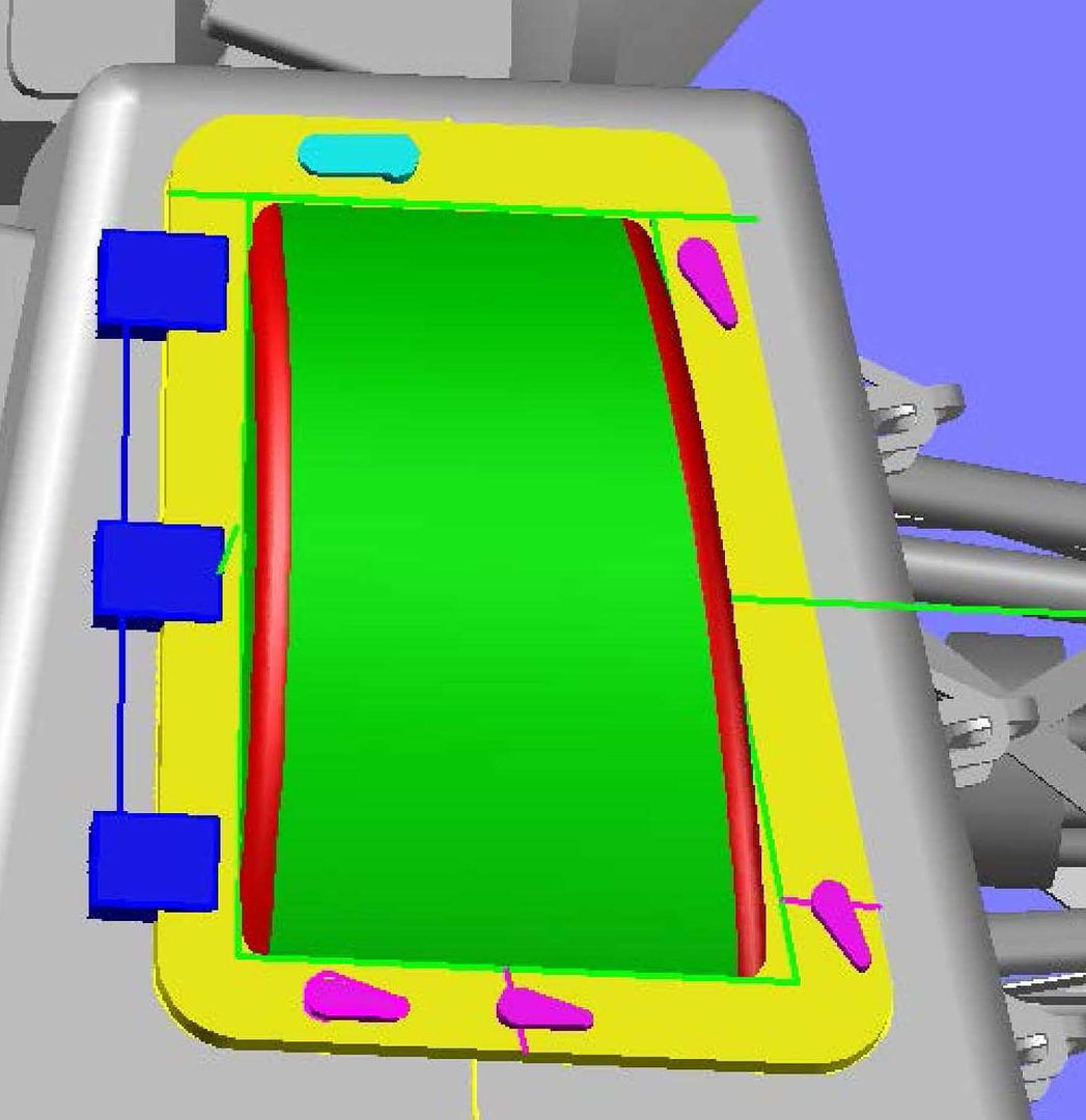 I recolored them to see what it looked like and I am fairly happy with it, and if it will print, I think it will look good at 1/350 scale. 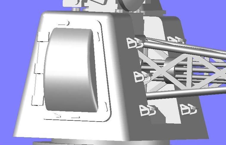 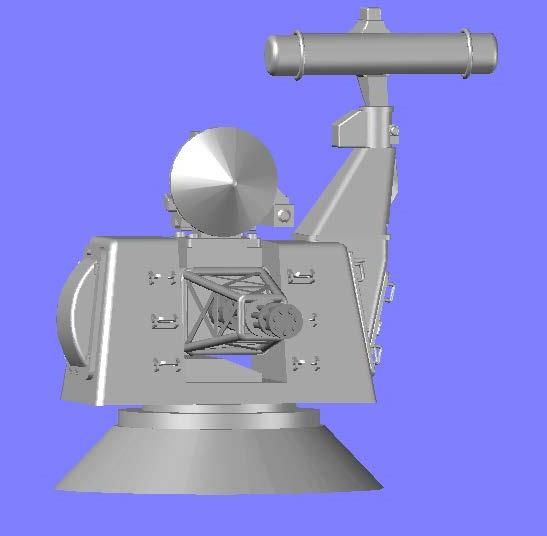 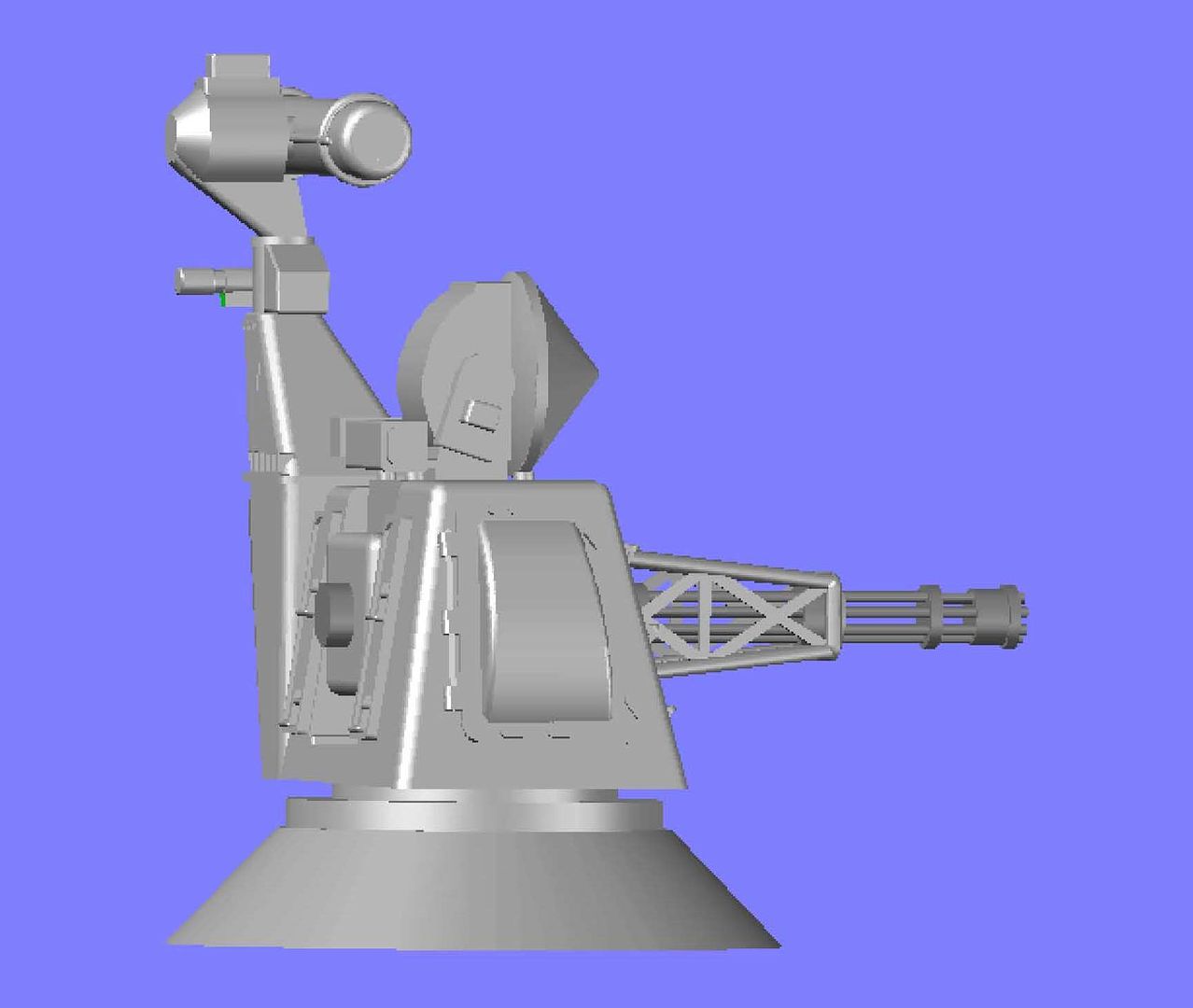 After some lunch, I am going to redo the back end of the barrel to finish it up (unless there are changes). CHEERS!!!
[u][b]UPDATE 11[/b][/u]
With the grabs finished (for now) I moved to the right side. The first thing I noticed was that I had not added the box to the radar support arm, so I added it. By extruding a rectangle and rounding the edges.
[url=http://s1352.photobucket.com/user/rdutnell/media/Goalkeeper/pix11_Page_02_zps1fde6d76.jpg.html][img]http://i1352.photobucket.com/albums/q659/rdutnell/Goalkeeper/pix11_Page_02_zps1fde6d76.jpg[/img][/url]
Next I prepared for the large rounded object on the side of the main body.
[url=http://s1352.photobucket.com/user/rdutnell/media/Goalkeeper/pix11_Page_01_zps209ebb81.jpg.html][img]http://i1352.photobucket.com/albums/q659/rdutnell/Goalkeeper/pix11_Page_01_zps209ebb81.jpg[/img][/url]
I first drew the outline of the outer plate.
[url=http://s1352.photobucket.com/user/rdutnell/media/Goalkeeper/pix11_Page_03_zps392770cf.jpg.html][img]http://i1352.photobucket.com/albums/q659/rdutnell/Goalkeeper/pix11_Page_03_zps392770cf.jpg[/img][/url]
I extruded it into the side, and then rounded the corners. For the main body, I joined an arc and line to form a polyline that I then extruded, and rounded the edges of the extrusion.
[url=http://s1352.photobucket.com/user/rdutnell/media/Goalkeeper/pix11_Page_04_zps247a87d3.jpg.html][img]http://i1352.photobucket.com/albums/q659/rdutnell/Goalkeeper/pix11_Page_04_zps247a87d3.jpg[/img][/url]
The rest of it was pretty much made up because I can’t really tell from the photos I have what the detailing on the side is. It almost looks like hinges on the left, so I used extruded rectangles to make them.
[url=http://s1352.photobucket.com/user/rdutnell/media/Goalkeeper/pix11_Page_05_zps811d3bc7.jpg.html][img]http://i1352.photobucket.com/albums/q659/rdutnell/Goalkeeper/pix11_Page_05_zps811d3bc7.jpg[/img][/url]
I also can’t tell what the objects around the bottom and right side. They appear to be some sort of tightening lever, or possibly a type of wing nut. In any case I winged them.
[url=http://s1352.photobucket.com/user/rdutnell/media/Goalkeeper/pix11_Page_06_zpsab49d6ec.jpg.html][img]http://i1352.photobucket.com/albums/q659/rdutnell/Goalkeeper/pix11_Page_06_zpsab49d6ec.jpg[/img][/url]
I had a pretty good picture of the object at the top that appears to be a relieve valve of some sort. I matched it as close as possible without getting below 0.04 mm in any dimension.
[url=http://s1352.photobucket.com/user/rdutnell/media/Goalkeeper/pix11_Page_07_zps5af0e798.jpg.html][img]http://i1352.photobucket.com/albums/q659/rdutnell/Goalkeeper/pix11_Page_07_zps5af0e798.jpg[/img][/url]
I recolored them to see what it looked like and I am fairly happy with it, and if it will print, I think it will look good at 1/350 scale.
[url=http://s1352.photobucket.com/user/rdutnell/media/Goalkeeper/pix11_Page_08_zps2ad51135.jpg.html][img]http://i1352.photobucket.com/albums/q659/rdutnell/Goalkeeper/pix11_Page_08_zps2ad51135.jpg[/img][/url]
[url=http://s1352.photobucket.com/user/rdutnell/media/Goalkeeper/pix11_Page_09_zpsc8ad8fd7.jpg.html][img]http://i1352.photobucket.com/albums/q659/rdutnell/Goalkeeper/pix11_Page_09_zpsc8ad8fd7.jpg[/img][/url]
[url=http://s1352.photobucket.com/user/rdutnell/media/Goalkeeper/pix11_Page_10_zpsb93d9469.jpg.html][img]http://i1352.photobucket.com/albums/q659/rdutnell/Goalkeeper/pix11_Page_10_zpsb93d9469.jpg[/img][/url]
After some lunch, I am going to redo the back end of the barrel to finish it up (unless there are changes).
CHEERS!!!
|
|
|
|
Posted: Sun Jun 02, 2013 12:51 pm |
|
|
|
|
|
| |
Post subject: |
Re: 1/350 Goalkeeper close-in weapon system (CIWS) in AutoCa |
|
|
UPDATE 10Hi Everybody! I made good progress last night and this morning, and thought I would post updates before the final push. As I said in the last post, the next thing I did was try to make the grabs/steps. Using the limited photos I have of the grabs, I made a rough outline, extruded it and rounded the lower edge. I also traced out the openings in the sides, extruded it… 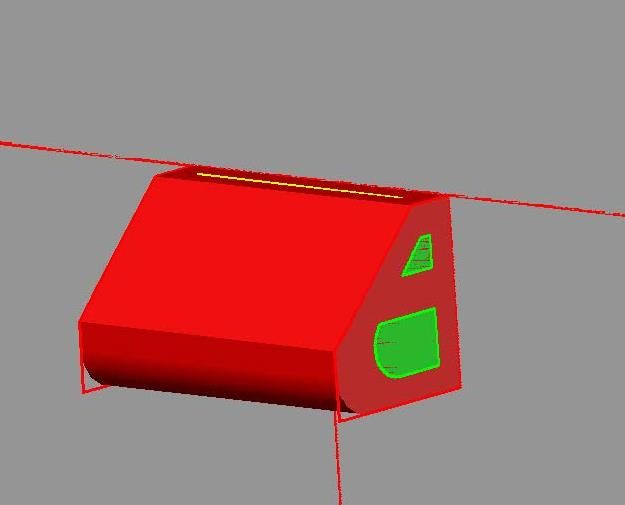 …And subtracted it. 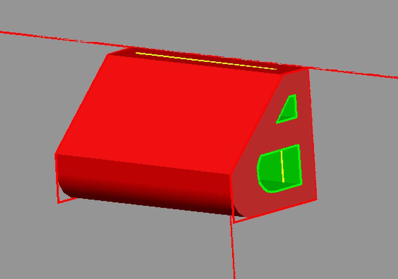 I then prepared to cut out the center by extruding a rectangle between what will be the end brackets. 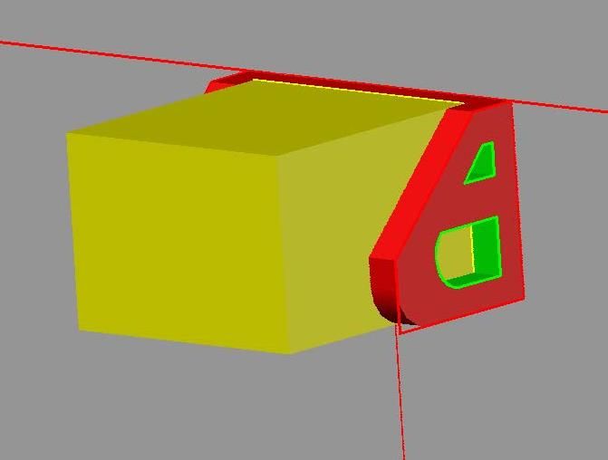 This was subtracted from the existing piece. 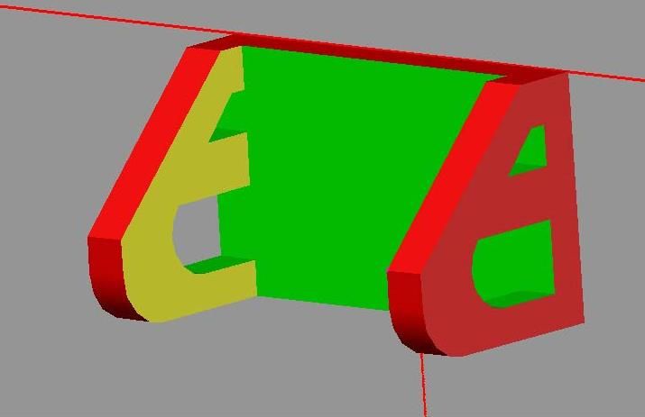 Next I made the grab itself using two circles connected with lines, then trimmed and joined to the lines to form a polyline which was then extruded. 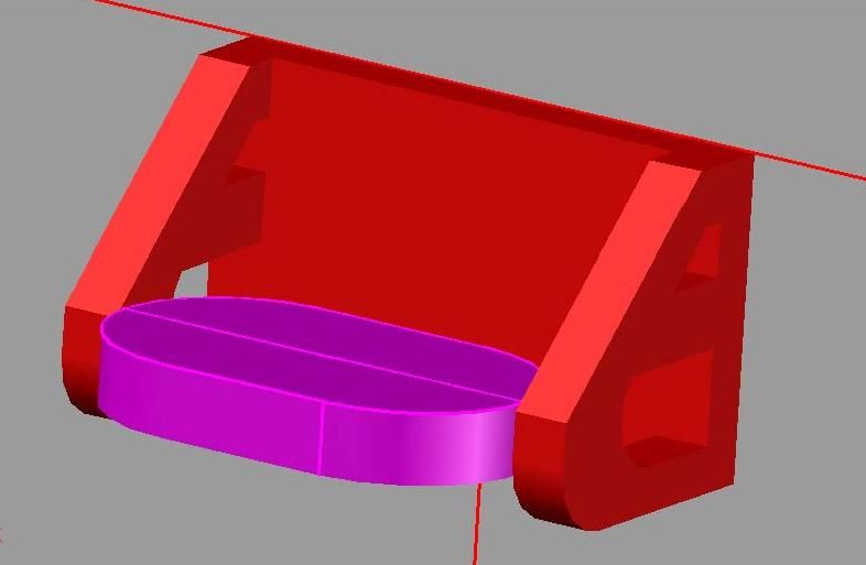 The shape was then shelled to hollow the center out, the two objects were joined and copied to the other locations observed in pictures. I ended up not liking it and completely redoing it, and I’m still not real happy with it, but unless I can find better pictures, it is the best I can do, so I am not going to redo it, but I am not going to attach them either. I did recolor them, to get a better feel for what it will look like. 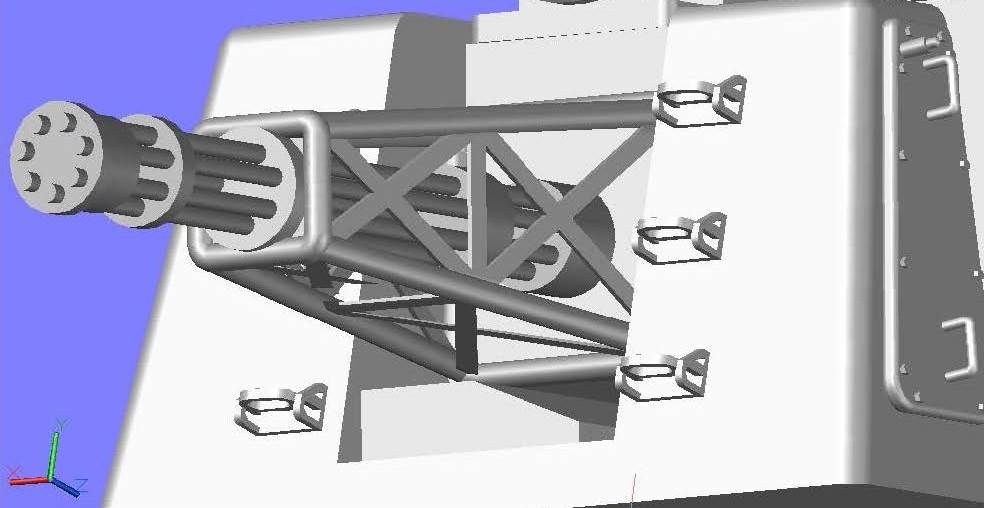 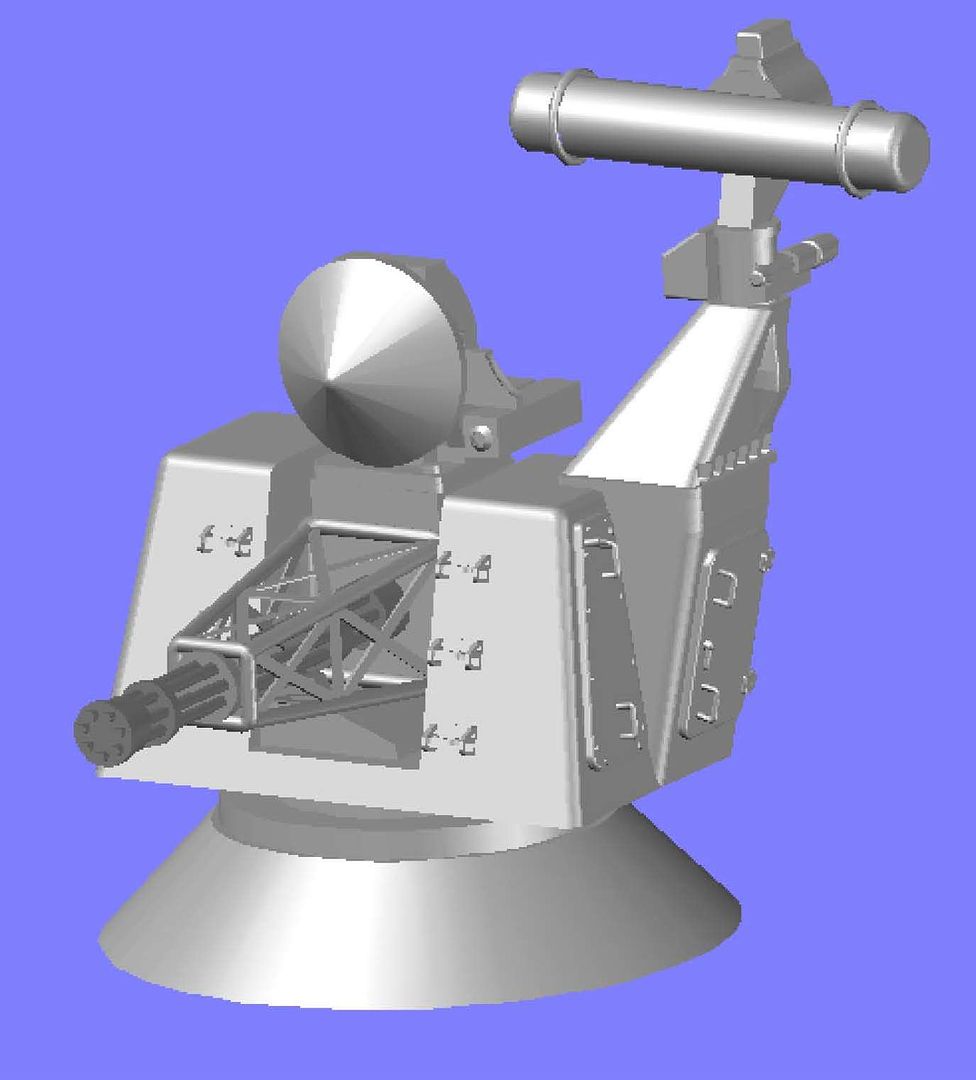 More to follow…
[u][b]UPDATE 10[/b][/u]
Hi Everybody!
I made good progress last night and this morning, and thought I would post updates before the final push. As I said in the last post, the next thing I did was try to make the grabs/steps.
Using the limited photos I have of the grabs, I made a rough outline, extruded it and rounded the lower edge. I also traced out the openings in the sides, extruded it…
[url=http://s1352.photobucket.com/user/rdutnell/media/Goalkeeper/pix10_Page_1_zpsf07ba878.jpg.html][img]http://i1352.photobucket.com/albums/q659/rdutnell/Goalkeeper/pix10_Page_1_zpsf07ba878.jpg[/img][/url]
…And subtracted it.
[url=http://s1352.photobucket.com/user/rdutnell/media/Goalkeeper/pix10_Page_2_zps2c103e60.jpg.html][img]http://i1352.photobucket.com/albums/q659/rdutnell/Goalkeeper/pix10_Page_2_zps2c103e60.jpg[/img][/url]
I then prepared to cut out the center by extruding a rectangle between what will be the end brackets.
[url=http://s1352.photobucket.com/user/rdutnell/media/Goalkeeper/pix10_Page_3_zps25f13529.jpg.html][img]http://i1352.photobucket.com/albums/q659/rdutnell/Goalkeeper/pix10_Page_3_zps25f13529.jpg[/img][/url]
This was subtracted from the existing piece.
[url=http://s1352.photobucket.com/user/rdutnell/media/Goalkeeper/pix10_Page_4_zps811ae1ef.jpg.html][img]http://i1352.photobucket.com/albums/q659/rdutnell/Goalkeeper/pix10_Page_4_zps811ae1ef.jpg[/img][/url]
Next I made the grab itself using two circles connected with lines, then trimmed and joined to the lines to form a polyline which was then extruded.
[url=http://s1352.photobucket.com/user/rdutnell/media/Goalkeeper/pix10_Page_5_zpsef769b8d.jpg.html][img]http://i1352.photobucket.com/albums/q659/rdutnell/Goalkeeper/pix10_Page_5_zpsef769b8d.jpg[/img][/url]
The shape was then shelled to hollow the center out, the two objects were joined and copied to the other locations observed in pictures. I ended up not liking it and completely redoing it, and I’m still not real happy with it, but unless I can find better pictures, it is the best I can do, so I am not going to redo it, but I am not going to attach them either. I did recolor them, to get a better feel for what it will look like.
[url=http://s1352.photobucket.com/user/rdutnell/media/Goalkeeper/pix10_Page_6_zpsd3191421.jpg.html][img]http://i1352.photobucket.com/albums/q659/rdutnell/Goalkeeper/pix10_Page_6_zpsd3191421.jpg[/img][/url]
[url=http://s1352.photobucket.com/user/rdutnell/media/Goalkeeper/pix10_Page_7_zps77577476.jpg.html][img]http://i1352.photobucket.com/albums/q659/rdutnell/Goalkeeper/pix10_Page_7_zps77577476.jpg[/img][/url]
More to follow…
|
|
|
|
Posted: Sun Jun 02, 2013 12:13 pm |
|
|
|
|
|
| |
Post subject: |
Re: 1/350 Goalkeeper close-in weapon system (CIWS) in AutoCa |
|
|
UPDATE 9 I next decided to make the access hatch on the left side, so I drew a polygon on the surface, positioned it correctly and filleted the corners. The top corners are filleted at a radius of 0.1 mm and the bottom corners at 0.2 mm radius. 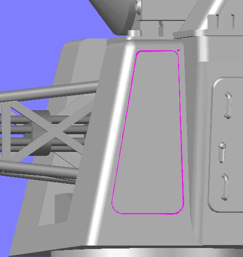 This shape was extruded out 0.13 mm. and the edges, inside and out, were rounded. 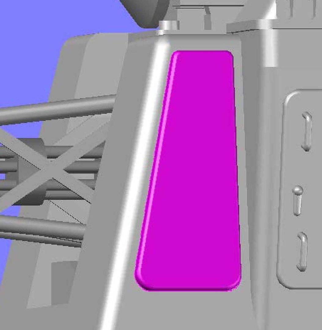 The next thing I did was add the handles. To do this I copied the hatch assembly to the side ad sliced off the handles and deleted the rest of the hatch. 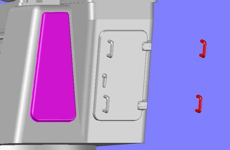 I then copied the handles to the center line of the plate using the center of the lowest handle as reference. 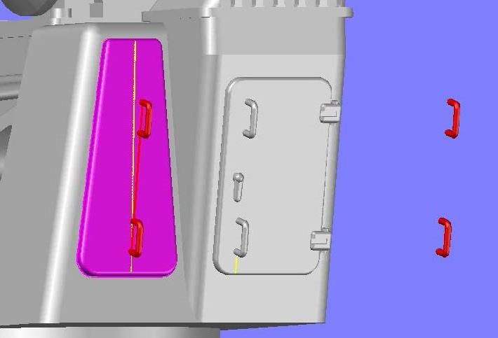 You can see that the handles weren’t lined up with the surface of the plate, so I had to rotate them before moving the top one up to the proper(?) position. 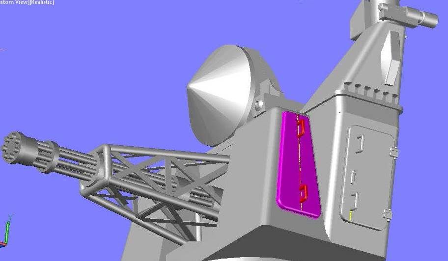 I next added the bolts to the edges using hexagons inscribed in a 0.4mm radius circle, and extruded 0.036 mm out from the surface. 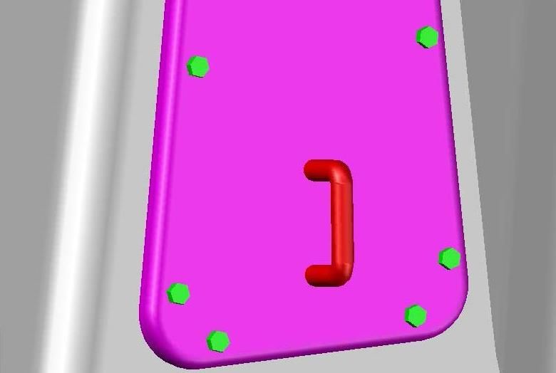 I also added whatever that thing is sticking out at the top left of the plate. The pictures I have don’t show it very well so I pretty much winged it. 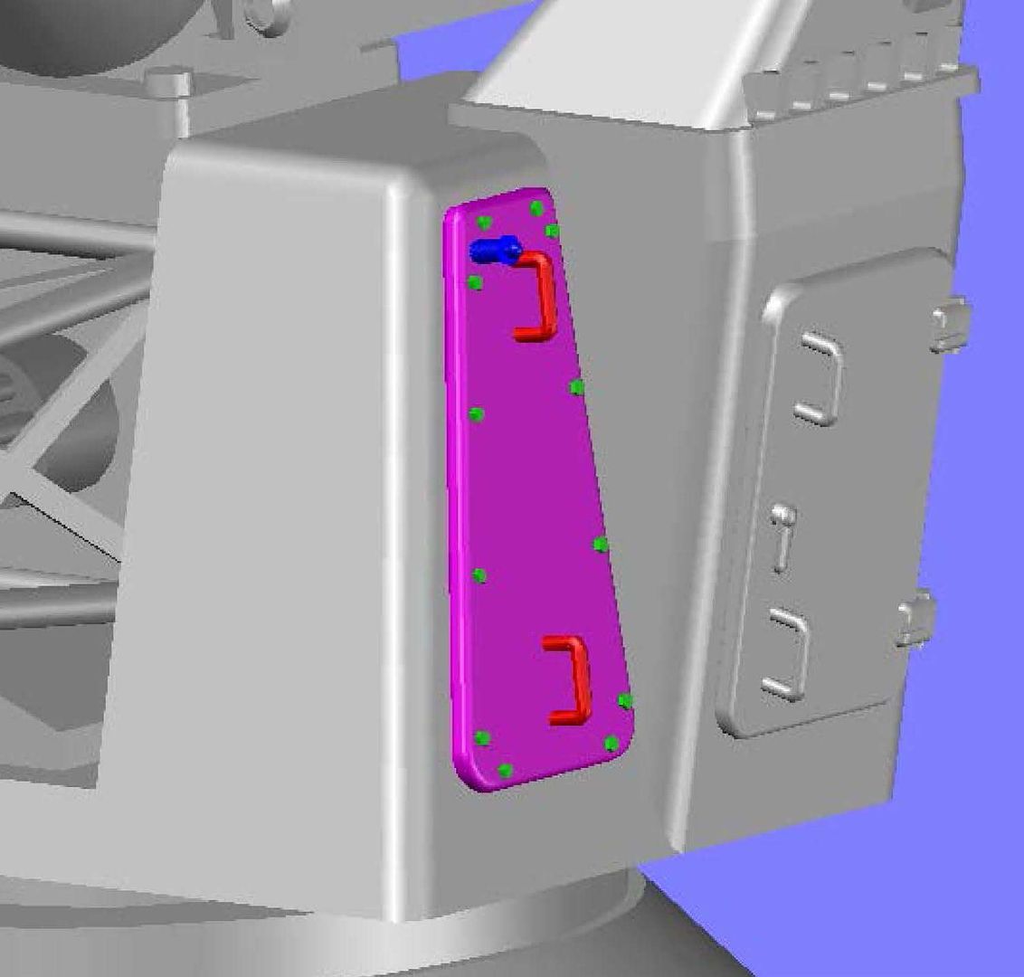 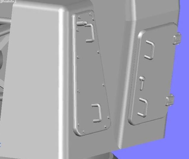 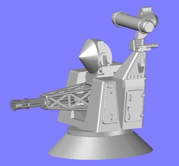 I am going to work on the front of the body next, which means making the steps/grabs. CHEERS!!!
[u][b]UPDATE 9[/b][/u]
I next decided to make the access hatch on the left side, so I drew a polygon on the surface, positioned it correctly and filleted the corners. The top corners are filleted at a radius of 0.1 mm and the bottom corners at 0.2 mm radius.
[url=http://s1352.photobucket.com/user/rdutnell/media/Goalkeeper/pix09_Page_01_zps62b8bf66.jpg.html][img]http://i1352.photobucket.com/albums/q659/rdutnell/Goalkeeper/pix09_Page_01_zps62b8bf66.jpg[/img][/url]
This shape was extruded out 0.13 mm. and the edges, inside and out, were rounded.
[url=http://s1352.photobucket.com/user/rdutnell/media/Goalkeeper/pix09_Page_02_zps6e1fe5e3.jpg.html][img]http://i1352.photobucket.com/albums/q659/rdutnell/Goalkeeper/pix09_Page_02_zps6e1fe5e3.jpg[/img][/url]
The next thing I did was add the handles. To do this I copied the hatch assembly to the side ad sliced off the handles and deleted the rest of the hatch.
[url=http://s1352.photobucket.com/user/rdutnell/media/Goalkeeper/pix09_Page_03_zps4e9db203.jpg.html][img]http://i1352.photobucket.com/albums/q659/rdutnell/Goalkeeper/pix09_Page_03_zps4e9db203.jpg[/img][/url]
I then copied the handles to the center line of the plate using the center of the lowest handle as reference.
[url=http://s1352.photobucket.com/user/rdutnell/media/Goalkeeper/pix09_Page_04_zps05bb6be9.jpg.html][img]http://i1352.photobucket.com/albums/q659/rdutnell/Goalkeeper/pix09_Page_04_zps05bb6be9.jpg[/img][/url]
You can see that the handles weren’t lined up with the surface of the plate, so I had to rotate them before moving the top one up to the proper(?) position.
[url=http://s1352.photobucket.com/user/rdutnell/media/Goalkeeper/pix09_Page_05_zpsdc77a716.jpg.html][img]http://i1352.photobucket.com/albums/q659/rdutnell/Goalkeeper/pix09_Page_05_zpsdc77a716.jpg[/img][/url]
I next added the bolts to the edges using hexagons inscribed in a 0.4mm radius circle, and extruded 0.036 mm out from the surface.
[url=http://s1352.photobucket.com/user/rdutnell/media/Goalkeeper/pix09_Page_06_zps7f96c7bd.jpg.html][img]http://i1352.photobucket.com/albums/q659/rdutnell/Goalkeeper/pix09_Page_06_zps7f96c7bd.jpg[/img][/url]
I also added whatever that thing is sticking out at the top left of the plate. The pictures I have don’t show it very well so I pretty much winged it.
[url=http://s1352.photobucket.com/user/rdutnell/media/Goalkeeper/pix09_Page_07_zpsd8cebb6d.jpg.html][img]http://i1352.photobucket.com/albums/q659/rdutnell/Goalkeeper/pix09_Page_07_zpsd8cebb6d.jpg[/img][/url]
[url=http://s1352.photobucket.com/user/rdutnell/media/Goalkeeper/pix09_Page_08_zps4dc6bb7f.jpg.html][img]http://i1352.photobucket.com/albums/q659/rdutnell/Goalkeeper/pix09_Page_08_zps4dc6bb7f.jpg[/img][/url]
[url=http://s1352.photobucket.com/user/rdutnell/media/Goalkeeper/pix09_Page_09_zpsf0195581.jpg.html][img]http://i1352.photobucket.com/albums/q659/rdutnell/Goalkeeper/pix09_Page_09_zpsf0195581.jpg[/img][/url]
I am going to work on the front of the body next, which means making the steps/grabs.
CHEERS!!!
|
|
|
|
Posted: Sat Jun 01, 2013 9:07 pm |
|
|
|
|
 and included the bow piece for my second Greenling model, and Goalkeepers and RAMs in both 1/350 scale and 1/700 scale. Here are a few pictures of the small pieces as they arrived. (Sorry that I didn’t put anything for scale but the weave is from a normal cotton sheet.)