| Author |
Message |
|
|
| |
Post subject: |
Re: USCGC Bertholf (WMSL-750) – A CAD Design for 3D Printing |
 |
|
|
Hi, I am in the process of building a 1/100 th scale R C model of 'Stratton', for obvious reasons the model can only be semi-scale. I started from the drawing board using any info / photos / diagrams I could find in the public domain. A fellow R C modeller found your site/forum and your work has helped me a lot.
I have virtually completed the hull and am now preparing the drawings for the superstructure and working out how I will build in access to the RC gear. This is the next challenge as the seamless stealth type structure does not make it easy.
Thanks a lot for sharing your work. I will watch your progress with interest.
Regards,
KG
|
|
|
 |
Posted: Thu Feb 04, 2016 8:54 am |
|
|
 |
|
|
| |
Post subject: |
Re: USCGC Bertholf (WMSL-750) – A CAD Design for 3D Printing |
|
|
It's been a while since I ckecked out this sight .Looks like you have been buisy .I had my plans enlarged to 1\48 but that is all that I have done .  It's been a while since I ckecked out this sight .Looks like you have been buisy .I had my plans enlarged to 1\48 but that is all that I have done . :wave_1:
|
|
|
|
Posted: Sun Jan 24, 2016 12:16 pm |
|
|
|
|
|
| |
Post subject: |
Re: USCGC Bertholf (WMSL-750) – A CAD Design for 3D Printing |
|
|
Hello, I am working on a 1/96 scale of this ship. Would you be interested in providing some 3D printed parts for builders to use? I know there are a lot of people that will be building this ship in the coming year. Things like the stacks and more would be very helpful to have. Please let me know. Your doing an amazing job. Eric Homeport Model Ships. http://www.homeportmodels.comHello,
I am working on a 1/96 scale of this ship. Would you be interested in providing some 3D printed parts for builders to use? I know there are a lot of people that will be building this ship in the coming year. Things like the stacks and more would be very helpful to have.
Please let me know. Your doing an amazing job.
Eric
Homeport Model Ships.
http://www.homeportmodels.com
|
|
|
|
Posted: Tue Nov 12, 2013 9:49 am |
|
|
|
|
|
| |
Post subject: |
Re: USCGC Bertholf (WMSL-750) – A CAD Design for 3D Printing |
|
|
UPDATE 55 Good Evening Everybody! I’ve been pretty busy over the last week, but have still managed to find time to make progress on Bertholf from time to time. My focus has been on the hangar aft bulkhead, starting with the loud speakers. I wasn’t sure the best way to go about it, but in the end I decided to use a polyline that I first drew flat on the bulkhead… 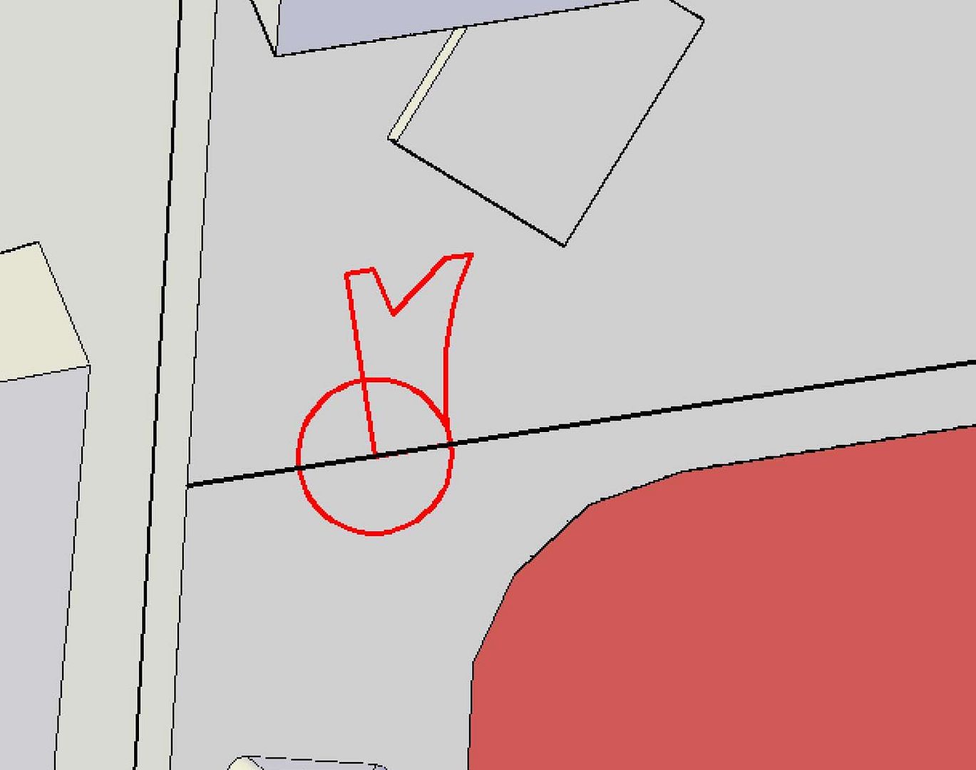 …Then rotated 90 degrees… 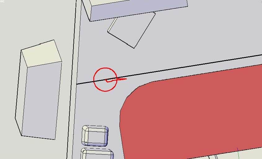 …Before revolving it about the circle. 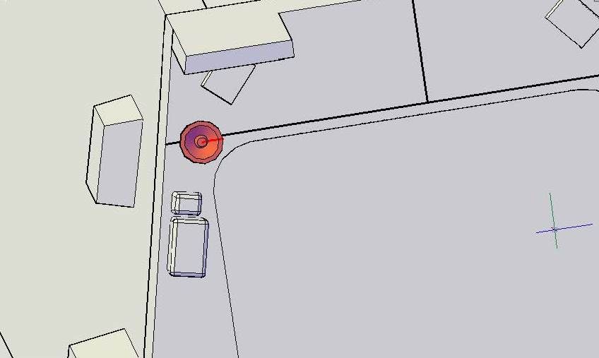 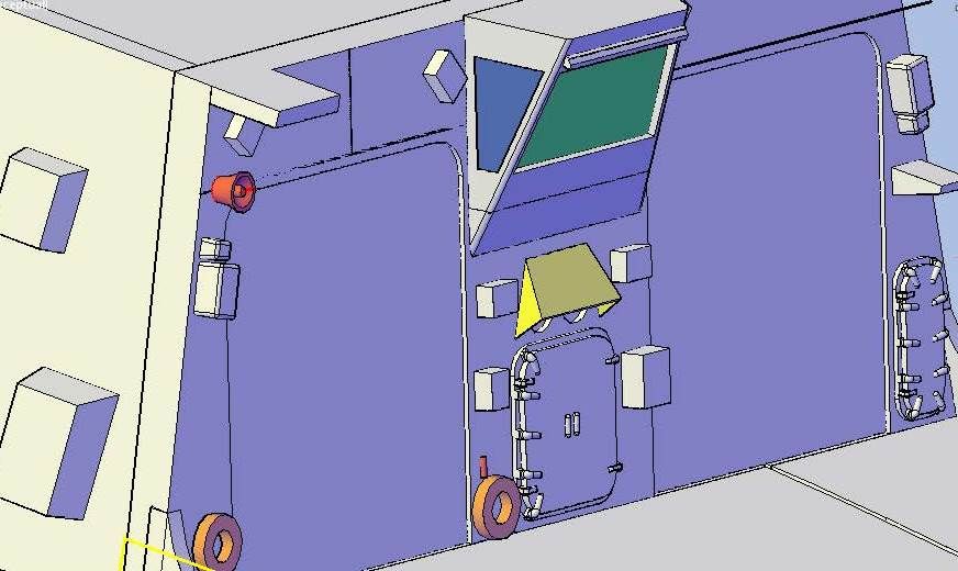 I then colored it gray and mirrored it to the other side. 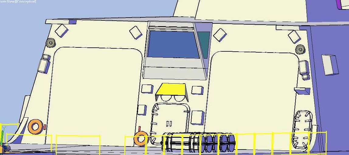 Next I added what appears to be a warning light on the starboard side of the hangar access doors. The light essentially consists of 2 lofted circles, the large of which I diced and sliced and removed the interior section, before joining everything together.  I then mirrored it to the port side of the doors.  Next, I made the little capstone shaped object on the lower platform on the starboard side. 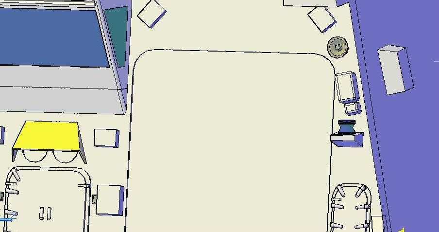 This was followed by the signal light over the starboard hangar door, which I started using an extruded rectangle.  To this I added an extruded circle in the middle, and then added a curved polyline… 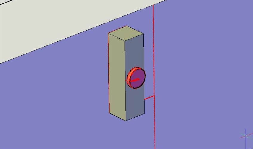 ..Which I revolved and added to the extruded circle before copying it all up and down and recoloring them.  After this I added the camera on the starboard side, starting with the base, which is again an extruded rectangle. 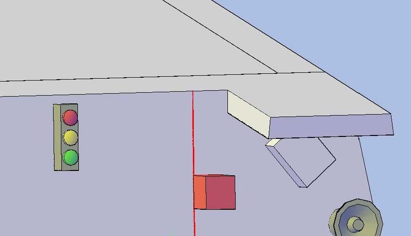 The body was next and consisted of a series of lofted and extruded shapes that I didn’t document well.  The camera itself was next and was an extruded rectangle that I sliced and removed the end of. 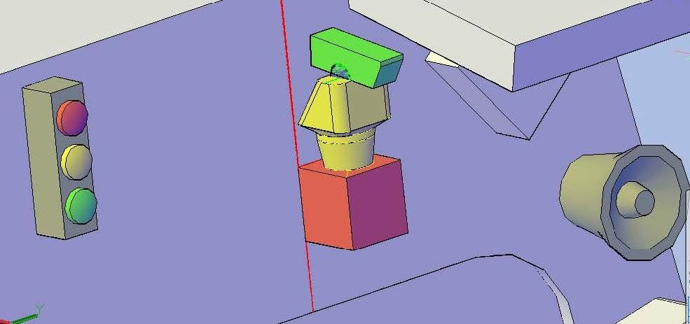 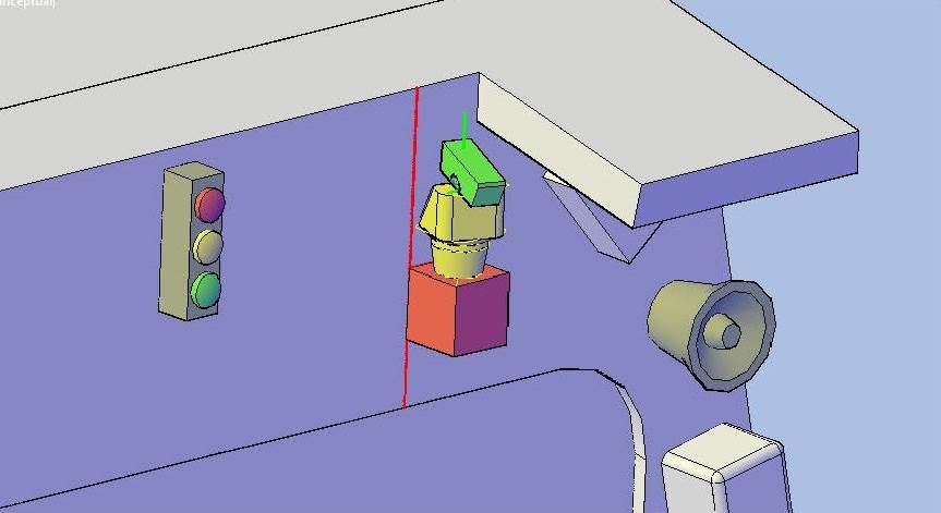 I then joined everything together and recolored it white… 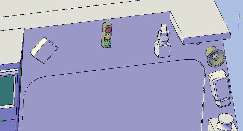 …Before mirroring it to the port side. 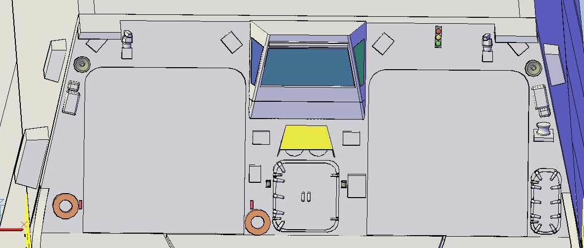 Next I added the lights along the top. The best picture I had to accomplish this is shown below.  I started by drawing positioning circles. 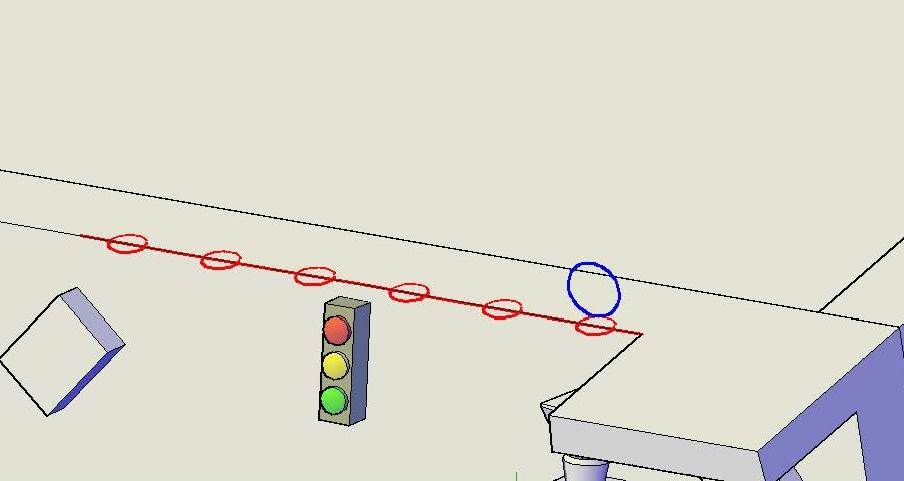 The lights themselves, I made using a sphere and an extruded circle. 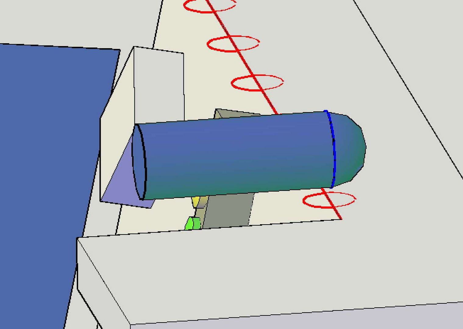 I then sliced the extruded circle to more or less match the pictures, rotated it vertically…  …And horizontally… 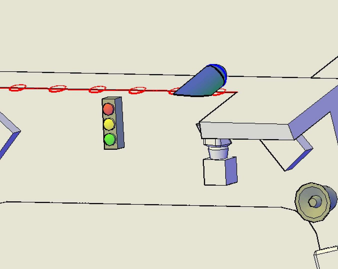 …Before copying it to the other locations on the starboard side. 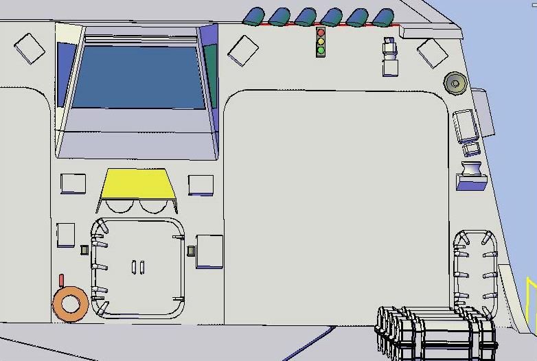 To attach the lights to the structure, I had to use a little modeling license again, due to the small size. I didn’t document the process, but the images below show the results.   I then copied the support to the other lights. Then, since in the picture of the lights, it is clear that each light has slightly different horizontal and vertical positioning, I rotated them individually in an attempt to match the picture.  I then colored the bases gray and the lights white…  …And mirrored them to the port side.  At this point I stopped, pending discussion with Pavel as to how he wants to attach these items. Does he want to print them individually or in groups? Rather than do something that would need to be redone I quit while I was ahead. CHEERS!!! UPDATE 55
Good Evening Everybody! :wave_1:
I’ve been pretty busy over the last week, but have still managed to find time to make progress on Bertholf from time to time. My focus has been on the hangar aft bulkhead, starting with the loud speakers. I wasn’t sure the best way to go about it, but in the end I decided to use a polyline that I first drew flat on the bulkhead…
[url=http://s1352.photobucket.com/user/rdutnell/media/USCG%20Cutter%20%20-%20Bertholf/USCGCutter-55-pix_Page_01_zps8dcb6c1f.jpg.html][img]http://i1352.photobucket.com/albums/q659/rdutnell/USCG%20Cutter%20%20-%20Bertholf/USCGCutter-55-pix_Page_01_zps8dcb6c1f.jpg[/img][/url]
…Then rotated 90 degrees…
[url=http://s1352.photobucket.com/user/rdutnell/media/USCG%20Cutter%20%20-%20Bertholf/USCGCutter-55-pix_Page_02_zps7ce64081.jpg.html][img]http://i1352.photobucket.com/albums/q659/rdutnell/USCG%20Cutter%20%20-%20Bertholf/USCGCutter-55-pix_Page_02_zps7ce64081.jpg[/img][/url]
…Before revolving it about the circle.
[url=http://s1352.photobucket.com/user/rdutnell/media/USCG%20Cutter%20%20-%20Bertholf/USCGCutter-55-pix_Page_03_zpse6a9e951.jpg.html][img]http://i1352.photobucket.com/albums/q659/rdutnell/USCG%20Cutter%20%20-%20Bertholf/USCGCutter-55-pix_Page_03_zpse6a9e951.jpg[/img][/url]
[url=http://s1352.photobucket.com/user/rdutnell/media/USCG%20Cutter%20%20-%20Bertholf/USCGCutter-55-pix_Page_04_zps99b91281.jpg.html][img]http://i1352.photobucket.com/albums/q659/rdutnell/USCG%20Cutter%20%20-%20Bertholf/USCGCutter-55-pix_Page_04_zps99b91281.jpg[/img][/url]
I then colored it gray and mirrored it to the other side.
[url=http://s1352.photobucket.com/user/rdutnell/media/USCG%20Cutter%20%20-%20Bertholf/USCGCutter-55-pix_Page_05_zps4fccebed.jpg.html][img]http://i1352.photobucket.com/albums/q659/rdutnell/USCG%20Cutter%20%20-%20Bertholf/USCGCutter-55-pix_Page_05_zps4fccebed.jpg[/img][/url]
Next I added what appears to be a warning light on the starboard side of the hangar access doors. The light essentially consists of 2 lofted circles, the large of which I diced and sliced and removed the interior section, before joining everything together.
[url=http://s1352.photobucket.com/user/rdutnell/media/USCG%20Cutter%20%20-%20Bertholf/USCGCutter-55-pix_Page_06_zps4ff98c6b.jpg.html][img]http://i1352.photobucket.com/albums/q659/rdutnell/USCG%20Cutter%20%20-%20Bertholf/USCGCutter-55-pix_Page_06_zps4ff98c6b.jpg[/img][/url]
I then mirrored it to the port side of the doors.
[url=http://s1352.photobucket.com/user/rdutnell/media/USCG%20Cutter%20%20-%20Bertholf/USCGCutter-55-pix_Page_07_zps140b2e77.jpg.html][img]http://i1352.photobucket.com/albums/q659/rdutnell/USCG%20Cutter%20%20-%20Bertholf/USCGCutter-55-pix_Page_07_zps140b2e77.jpg[/img][/url]
Next, I made the little capstone shaped object on the lower platform on the starboard side.
[url=http://s1352.photobucket.com/user/rdutnell/media/USCG%20Cutter%20%20-%20Bertholf/USCGCutter-55-pix_Page_08_zpsd739b8e7.jpg.html][img]http://i1352.photobucket.com/albums/q659/rdutnell/USCG%20Cutter%20%20-%20Bertholf/USCGCutter-55-pix_Page_08_zpsd739b8e7.jpg[/img][/url]
This was followed by the signal light over the starboard hangar door, which I started using an extruded rectangle.
[url=http://s1352.photobucket.com/user/rdutnell/media/USCG%20Cutter%20%20-%20Bertholf/USCGCutter-55-pix_Page_09_zpscb36b1f8.jpg.html][img]http://i1352.photobucket.com/albums/q659/rdutnell/USCG%20Cutter%20%20-%20Bertholf/USCGCutter-55-pix_Page_09_zpscb36b1f8.jpg[/img][/url]
To this I added an extruded circle in the middle, and then added a curved polyline…
[url=http://s1352.photobucket.com/user/rdutnell/media/USCG%20Cutter%20%20-%20Bertholf/USCGCutter-55-pix_Page_10_zps90866094.jpg.html][img]http://i1352.photobucket.com/albums/q659/rdutnell/USCG%20Cutter%20%20-%20Bertholf/USCGCutter-55-pix_Page_10_zps90866094.jpg[/img][/url]
..Which I revolved and added to the extruded circle before copying it all up and down and recoloring them.
[url=http://s1352.photobucket.com/user/rdutnell/media/USCG%20Cutter%20%20-%20Bertholf/USCGCutter-55-pix_Page_11_zpsd997bc82.jpg.html][img]http://i1352.photobucket.com/albums/q659/rdutnell/USCG%20Cutter%20%20-%20Bertholf/USCGCutter-55-pix_Page_11_zpsd997bc82.jpg[/img][/url]
After this I added the camera on the starboard side, starting with the base, which is again an extruded rectangle.
[url=http://s1352.photobucket.com/user/rdutnell/media/USCG%20Cutter%20%20-%20Bertholf/USCGCutter-55-pix_Page_12_zps729dc706.jpg.html][img]http://i1352.photobucket.com/albums/q659/rdutnell/USCG%20Cutter%20%20-%20Bertholf/USCGCutter-55-pix_Page_12_zps729dc706.jpg[/img][/url]
The body was next and consisted of a series of lofted and extruded shapes that I didn’t document well.
[url=http://s1352.photobucket.com/user/rdutnell/media/USCG%20Cutter%20%20-%20Bertholf/USCGCutter-55-pix_Page_13_zpsef4a0914.jpg.html][img]http://i1352.photobucket.com/albums/q659/rdutnell/USCG%20Cutter%20%20-%20Bertholf/USCGCutter-55-pix_Page_13_zpsef4a0914.jpg[/img][/url]
The camera itself was next and was an extruded rectangle that I sliced and removed the end of.
[url=http://s1352.photobucket.com/user/rdutnell/media/USCG%20Cutter%20%20-%20Bertholf/USCGCutter-55-pix_Page_14_zpsa8dd57bd.jpg.html][img]http://i1352.photobucket.com/albums/q659/rdutnell/USCG%20Cutter%20%20-%20Bertholf/USCGCutter-55-pix_Page_14_zpsa8dd57bd.jpg[/img][/url]
[url=http://s1352.photobucket.com/user/rdutnell/media/USCG%20Cutter%20%20-%20Bertholf/USCGCutter-55-pix_Page_15_zpsb28d59d1.jpg.html][img]http://i1352.photobucket.com/albums/q659/rdutnell/USCG%20Cutter%20%20-%20Bertholf/USCGCutter-55-pix_Page_15_zpsb28d59d1.jpg[/img][/url]
I then joined everything together and recolored it white…
[url=http://s1352.photobucket.com/user/rdutnell/media/USCG%20Cutter%20%20-%20Bertholf/USCGCutter-55-pix_Page_16_zpsb82e1ab3.jpg.html][img]http://i1352.photobucket.com/albums/q659/rdutnell/USCG%20Cutter%20%20-%20Bertholf/USCGCutter-55-pix_Page_16_zpsb82e1ab3.jpg[/img][/url]
…Before mirroring it to the port side.
[url=http://s1352.photobucket.com/user/rdutnell/media/USCG%20Cutter%20%20-%20Bertholf/USCGCutter-55-pix_Page_17_zps900288b5.jpg.html][img]http://i1352.photobucket.com/albums/q659/rdutnell/USCG%20Cutter%20%20-%20Bertholf/USCGCutter-55-pix_Page_17_zps900288b5.jpg[/img][/url]
Next I added the lights along the top. The best picture I had to accomplish this is shown below.
[url=http://s1352.photobucket.com/user/rdutnell/media/USCG%20Cutter%20%20-%20Bertholf/IMG_1902_zpsf67e0dbc.jpg.html][img]http://i1352.photobucket.com/albums/q659/rdutnell/USCG%20Cutter%20%20-%20Bertholf/IMG_1902_zpsf67e0dbc.jpg[/img][/url]
I started by drawing positioning circles.
[url=http://s1352.photobucket.com/user/rdutnell/media/USCG%20Cutter%20%20-%20Bertholf/USCGCutter-55-pix_Page_18_zps3db0ad2b.jpg.html][img]http://i1352.photobucket.com/albums/q659/rdutnell/USCG%20Cutter%20%20-%20Bertholf/USCGCutter-55-pix_Page_18_zps3db0ad2b.jpg[/img][/url]
The lights themselves, I made using a sphere and an extruded circle.
[url=http://s1352.photobucket.com/user/rdutnell/media/USCG%20Cutter%20%20-%20Bertholf/USCGCutter-55-pix_Page_19_zpsc954268d.jpg.html][img]http://i1352.photobucket.com/albums/q659/rdutnell/USCG%20Cutter%20%20-%20Bertholf/USCGCutter-55-pix_Page_19_zpsc954268d.jpg[/img][/url]
I then sliced the extruded circle to more or less match the pictures, rotated it vertically…
[url=http://s1352.photobucket.com/user/rdutnell/media/USCG%20Cutter%20%20-%20Bertholf/USCGCutter-55-pix_Page_20_zps6b2be5aa.jpg.html][img]http://i1352.photobucket.com/albums/q659/rdutnell/USCG%20Cutter%20%20-%20Bertholf/USCGCutter-55-pix_Page_20_zps6b2be5aa.jpg[/img][/url]
…And horizontally…
[url=http://s1352.photobucket.com/user/rdutnell/media/USCG%20Cutter%20%20-%20Bertholf/USCGCutter-55-pix_Page_21_zps3692fba5.jpg.html][img]http://i1352.photobucket.com/albums/q659/rdutnell/USCG%20Cutter%20%20-%20Bertholf/USCGCutter-55-pix_Page_21_zps3692fba5.jpg[/img][/url]
…Before copying it to the other locations on the starboard side.
[url=http://s1352.photobucket.com/user/rdutnell/media/USCG%20Cutter%20%20-%20Bertholf/USCGCutter-55-pix_Page_22_zps810a027e.jpg.html][img]http://i1352.photobucket.com/albums/q659/rdutnell/USCG%20Cutter%20%20-%20Bertholf/USCGCutter-55-pix_Page_22_zps810a027e.jpg[/img][/url]
To attach the lights to the structure, I had to use a little modeling license again, due to the small size. I didn’t document the process, but the images below show the results.
[url=http://s1352.photobucket.com/user/rdutnell/media/USCG%20Cutter%20%20-%20Bertholf/USCGCutter-55-pix_Page_23_zpsd2eefe62.jpg.html][img]http://i1352.photobucket.com/albums/q659/rdutnell/USCG%20Cutter%20%20-%20Bertholf/USCGCutter-55-pix_Page_23_zpsd2eefe62.jpg[/img][/url]
[url=http://s1352.photobucket.com/user/rdutnell/media/USCG%20Cutter%20%20-%20Bertholf/USCGCutter-55-pix_Page_24_zps517e9ece.jpg.html][img]http://i1352.photobucket.com/albums/q659/rdutnell/USCG%20Cutter%20%20-%20Bertholf/USCGCutter-55-pix_Page_24_zps517e9ece.jpg[/img][/url]
I then copied the support to the other lights. Then, since in the picture of the lights, it is clear that each light has slightly different horizontal and vertical positioning, I rotated them individually in an attempt to match the picture.
[url=http://s1352.photobucket.com/user/rdutnell/media/USCG%20Cutter%20%20-%20Bertholf/USCGCutter-55-pix_Page_25_zps5ea0cc48.jpg.html][img]http://i1352.photobucket.com/albums/q659/rdutnell/USCG%20Cutter%20%20-%20Bertholf/USCGCutter-55-pix_Page_25_zps5ea0cc48.jpg[/img][/url]
I then colored the bases gray and the lights white…
[url=http://s1352.photobucket.com/user/rdutnell/media/USCG%20Cutter%20%20-%20Bertholf/USCGCutter-55-pix_Page_26_zpsacb7fbd0.jpg.html][img]http://i1352.photobucket.com/albums/q659/rdutnell/USCG%20Cutter%20%20-%20Bertholf/USCGCutter-55-pix_Page_26_zpsacb7fbd0.jpg[/img][/url]
…And mirrored them to the port side.
[url=http://s1352.photobucket.com/user/rdutnell/media/USCG%20Cutter%20%20-%20Bertholf/USCGCutter-55-pix_Page_27_zps14faf757.jpg.html][img]http://i1352.photobucket.com/albums/q659/rdutnell/USCG%20Cutter%20%20-%20Bertholf/USCGCutter-55-pix_Page_27_zps14faf757.jpg[/img][/url]
At this point I stopped, pending discussion with Pavel as to how he wants to attach these items. Does he want to print them individually or in groups? Rather than do something that would need to be redone I quit while I was ahead.
CHEERS!!!
:wave_1:
|
|
|
|
Posted: Wed Jul 31, 2013 5:35 pm |
|
|
|
|
|
| |
Post subject: |
Re: USCGC Bertholf (WMSL-750) – A CAD Design for 3D Printing |
|
|
UPDATE 54 Good Morning guys, Well last night I had a slight diversion from the hangar bulkhead, deciding to put the safety net mounts on the hull and helo deck extension. The nets themselves will most likely be made with PE, but I think the mounts (or brackets) will print nicely as part of the hull and extension parts. I started by drawing lines along the center of the posts (vertical and horizontal) and separating the posts/netting from the mounts. 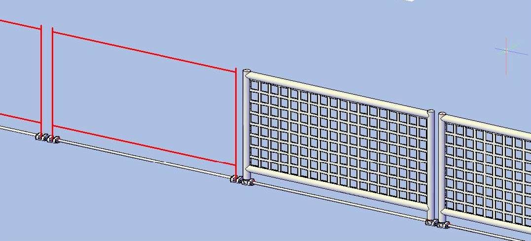 To make the rods connecting the mounts stouter, I took a little modeler’s license and added an extruded polygon to connect it to the adjoining part, either one of the hulls or the helo deck extension. In the image below the one on the left has been joined to the rod and mounts. The one on the right has just been extruded. 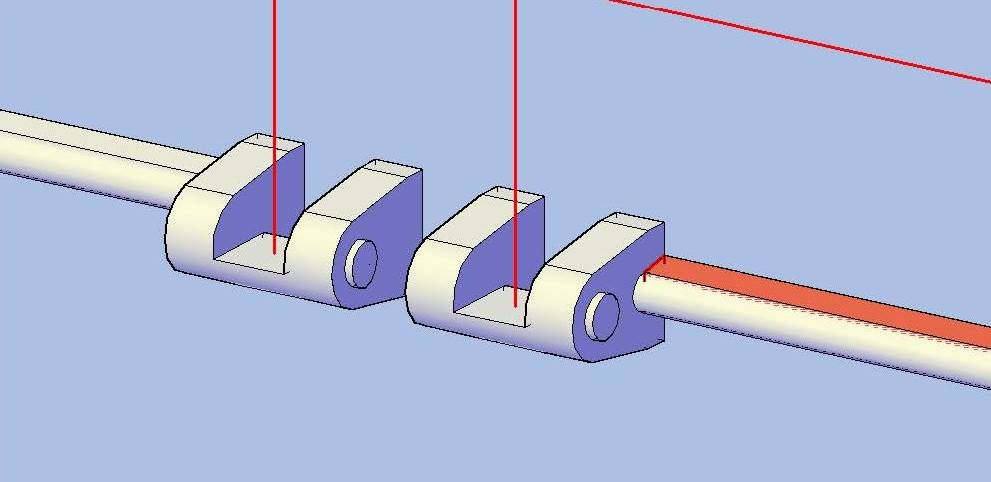 I did this all around the deck, copying, rotating and mirroring as needed and to simplify the process. The image below shows all of the mounts (with rods) and the netting lines. 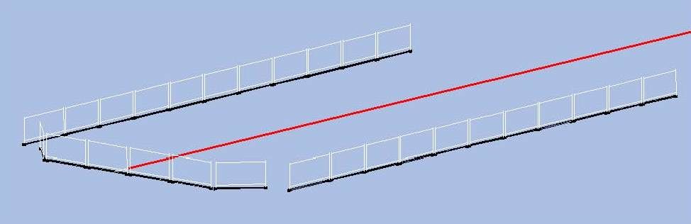 Next, I copied them to the model. Since the netting will be PE, I colored it yellow, as I will do for all PE on the model (although I may change it back from time to time for clipping images). 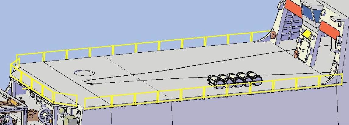 The mounts/rods extend across three separate hull pieces, so I had to slice them at the joints between pieces, including between the fantail and the helo deck… 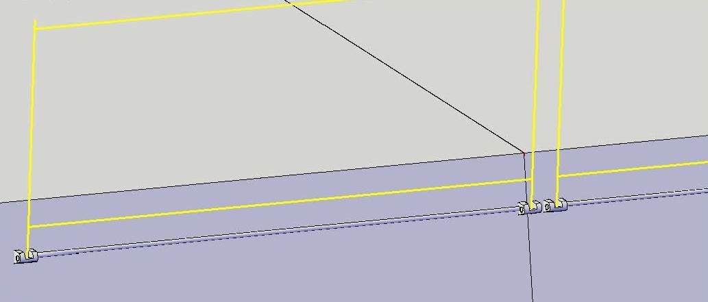 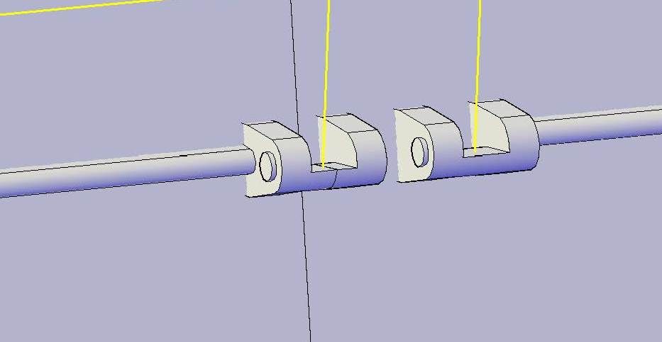 …And between the helo deck and the hangar. 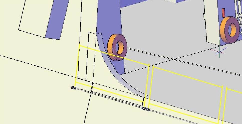 The last step was to join them to their respective parts. 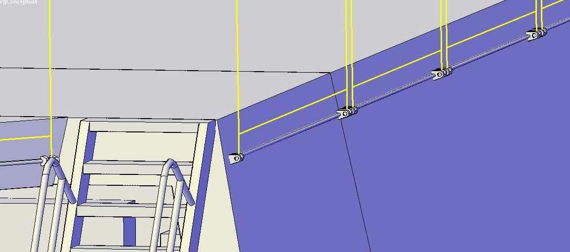 CHEERS!!! UPDATE 54
Good Morning guys, :wave_1:
Well last night I had a slight diversion from the hangar bulkhead, deciding to put the safety net mounts on the hull and helo deck extension. The nets themselves will most likely be made with PE, but I think the mounts (or brackets) will print nicely as part of the hull and extension parts. I started by drawing lines along the center of the posts (vertical and horizontal) and separating the posts/netting from the mounts.
[url=http://s1352.photobucket.com/user/rdutnell/media/USCG%20Cutter%20%20-%20Bertholf/USCGCutter-54-pix_Page_1_zpsca87cf52.jpg.html][img]http://i1352.photobucket.com/albums/q659/rdutnell/USCG%20Cutter%20%20-%20Bertholf/USCGCutter-54-pix_Page_1_zpsca87cf52.jpg[/img][/url]
To make the rods connecting the mounts stouter, I took a little modeler’s license and added an extruded polygon to connect it to the adjoining part, either one of the hulls or the helo deck extension. In the image below the one on the left has been joined to the rod and mounts. The one on the right has just been extruded.
[url=http://s1352.photobucket.com/user/rdutnell/media/USCG%20Cutter%20%20-%20Bertholf/USCGCutter-54-pix_Page_2_zps073e8d89.jpg.html][img]http://i1352.photobucket.com/albums/q659/rdutnell/USCG%20Cutter%20%20-%20Bertholf/USCGCutter-54-pix_Page_2_zps073e8d89.jpg[/img][/url]
I did this all around the deck, copying, rotating and mirroring as needed and to simplify the process. The image below shows all of the mounts (with rods) and the netting lines.
[url=http://s1352.photobucket.com/user/rdutnell/media/USCG%20Cutter%20%20-%20Bertholf/USCGCutter-54-pix_Page_3_zpsc68e3239.jpg.html][img]http://i1352.photobucket.com/albums/q659/rdutnell/USCG%20Cutter%20%20-%20Bertholf/USCGCutter-54-pix_Page_3_zpsc68e3239.jpg[/img][/url]
Next, I copied them to the model. Since the netting will be PE, I colored it yellow, as I will do for all PE on the model (although I may change it back from time to time for clipping images).
[url=http://s1352.photobucket.com/user/rdutnell/media/USCG%20Cutter%20%20-%20Bertholf/USCGCutter-54-pix_Page_4_zpsf31d466d.jpg.html][img]http://i1352.photobucket.com/albums/q659/rdutnell/USCG%20Cutter%20%20-%20Bertholf/USCGCutter-54-pix_Page_4_zpsf31d466d.jpg[/img][/url]
The mounts/rods extend across three separate hull pieces, so I had to slice them at the joints between pieces, including between the fantail and the helo deck…
[url=http://s1352.photobucket.com/user/rdutnell/media/USCG%20Cutter%20%20-%20Bertholf/USCGCutter-54-pix_Page_5_zpsbc4cd00d.jpg.html][img]http://i1352.photobucket.com/albums/q659/rdutnell/USCG%20Cutter%20%20-%20Bertholf/USCGCutter-54-pix_Page_5_zpsbc4cd00d.jpg[/img][/url]
[url=http://s1352.photobucket.com/user/rdutnell/media/USCG%20Cutter%20%20-%20Bertholf/USCGCutter-54-pix_Page_6_zps646e132a.jpg.html][img]http://i1352.photobucket.com/albums/q659/rdutnell/USCG%20Cutter%20%20-%20Bertholf/USCGCutter-54-pix_Page_6_zps646e132a.jpg[/img][/url]
…And between the helo deck and the hangar.
[url=http://s1352.photobucket.com/user/rdutnell/media/USCG%20Cutter%20%20-%20Bertholf/USCGCutter-54-pix_Page_7_zps13cf4aee.jpg.html][img]http://i1352.photobucket.com/albums/q659/rdutnell/USCG%20Cutter%20%20-%20Bertholf/USCGCutter-54-pix_Page_7_zps13cf4aee.jpg[/img][/url]
The last step was to join them to their respective parts.
[url=http://s1352.photobucket.com/user/rdutnell/media/USCG%20Cutter%20%20-%20Bertholf/USCGCutter-54-pix_Page_8_zpsc9a4c15f.jpg.html][img]http://i1352.photobucket.com/albums/q659/rdutnell/USCG%20Cutter%20%20-%20Bertholf/USCGCutter-54-pix_Page_8_zpsc9a4c15f.jpg[/img][/url]
CHEERS!!!
|
|
|
|
Posted: Sun Jul 28, 2013 11:00 am |
|
|
|
|
|
| |
Post subject: |
Re: USCGC Bertholf (WMSL-750) – A CAD Design for 3D Printing |
|
|
UPDATE 53 Hi guys! I didn’t get much modeling done while I was gone, but I did find some good pictures of the hangar aft bulkhead, including the one below. 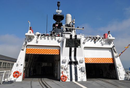 I did get a little done on the model one night, using the picture and staying up until 2AM to add make the rear access door, which I did by dicing and slicing the water tight door and using the components to make a larger door. The center bar seen in the image will need to be made with PE. When I got home yesterday, I continued by drilling the vent holes above the doorway partially into the bulkhead and adding the vent hood and electrical boxes seen on the center section. The vent hood will also need to be made out of PE, but I made one anyway and created a separate layer for it. It won’t be printed, because it is too thin, but it will make the virtual model look more complete. 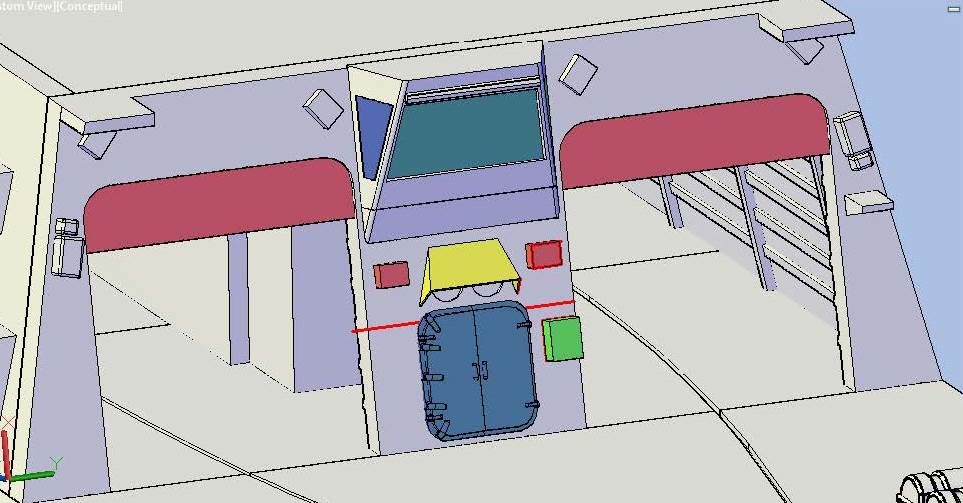 This morning I continued where I left off and made the last box on the center section and added a watertight door to the starboard side. (For some reason, every time I open the drawing some of the parts, including the aviation control station, change color, even though it says they are the correct color. 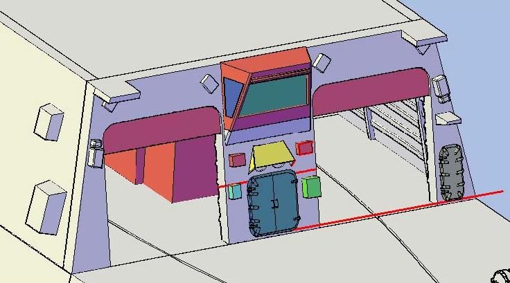 Looking at the pictures I noticed that the corners had the rounded plates like the ones on the forward side, so I added them as I had previously done on the forward side, but didn’t document. 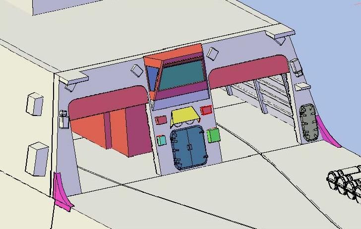 Because the plates would be pointed at the ends, if made flush with the deck and bulkhead, to the point that I don’t think that they would print very good, I decided to make them separate parts so that the ends of the parts would be 0.025" x 0.025" squares instead of points.  Next I added the life ring in the center section…  …Then to the port side.  After that I added the fire extinguishers and joined everything to the bulkhead (except the vent hood). I left the life rings orange (I know they are orange red, but I couldn’t find a good color match in AutoCad) and the fire extinguishers red.  I have a few more things to add tonight. CHEERS!!! UPDATE 53
Hi guys! :wave_1:
I didn’t get much modeling done while I was gone, but I did find some good pictures of the hangar aft bulkhead, including the one below.
[url=http://s1352.photobucket.com/user/rdutnell/media/USCG%20Cutter%20%20-%20Bertholf/hangar-aft_zpsbd941ef0.jpg.html][img]http://i1352.photobucket.com/albums/q659/rdutnell/USCG%20Cutter%20%20-%20Bertholf/hangar-aft_zpsbd941ef0.jpg[/img][/url]
I did get a little done on the model one night, using the picture and staying up until 2AM to add make the rear access door, which I did by dicing and slicing the water tight door and using the components to make a larger door. The center bar seen in the image will need to be made with PE.
When I got home yesterday, I continued by drilling the vent holes above the doorway partially into the bulkhead and adding the vent hood and electrical boxes seen on the center section. The vent hood will also need to be made out of PE, but I made one anyway and created a separate layer for it. It won’t be printed, because it is too thin, but it will make the virtual model look more complete.
[url=http://s1352.photobucket.com/user/rdutnell/media/USCG%20Cutter%20%20-%20Bertholf/USCGCutter-53-pix_Page_1_zps0170d68f.jpg.html][img]http://i1352.photobucket.com/albums/q659/rdutnell/USCG%20Cutter%20%20-%20Bertholf/USCGCutter-53-pix_Page_1_zps0170d68f.jpg[/img][/url]
This morning I continued where I left off and made the last box on the center section and added a watertight door to the starboard side. (For some reason, every time I open the drawing some of the parts, including the aviation control station, change color, even though it says they are the correct color.
[url=http://s1352.photobucket.com/user/rdutnell/media/USCG%20Cutter%20%20-%20Bertholf/USCGCutter-53-pix_Page_2_zps8185608d.jpg.html][img]http://i1352.photobucket.com/albums/q659/rdutnell/USCG%20Cutter%20%20-%20Bertholf/USCGCutter-53-pix_Page_2_zps8185608d.jpg[/img][/url]
Looking at the pictures I noticed that the corners had the rounded plates like the ones on the forward side, so I added them as I had previously done on the forward side, but didn’t document.
[url=http://s1352.photobucket.com/user/rdutnell/media/USCG%20Cutter%20%20-%20Bertholf/USCGCutter-53-pix_Page_3_zps99010d09.jpg.html][img]http://i1352.photobucket.com/albums/q659/rdutnell/USCG%20Cutter%20%20-%20Bertholf/USCGCutter-53-pix_Page_3_zps99010d09.jpg[/img][/url]
Because the plates would be pointed at the ends, if made flush with the deck and bulkhead, to the point that I don’t think that they would print very good, I decided to make them separate parts so that the ends of the parts would be 0.025" x 0.025" squares instead of points.
[url=http://s1352.photobucket.com/user/rdutnell/media/USCG%20Cutter%20%20-%20Bertholf/USCGCutter-53-pix_Page_7_zpsf34b5287.jpg.html][img]http://i1352.photobucket.com/albums/q659/rdutnell/USCG%20Cutter%20%20-%20Bertholf/USCGCutter-53-pix_Page_7_zpsf34b5287.jpg[/img][/url]
Next I added the life ring in the center section…
[url=http://s1352.photobucket.com/user/rdutnell/media/USCG%20Cutter%20%20-%20Bertholf/USCGCutter-53-pix_Page_4_zps3fd92df5.jpg.html][img]http://i1352.photobucket.com/albums/q659/rdutnell/USCG%20Cutter%20%20-%20Bertholf/USCGCutter-53-pix_Page_4_zps3fd92df5.jpg[/img][/url]
…Then to the port side.
[url=http://s1352.photobucket.com/user/rdutnell/media/USCG%20Cutter%20%20-%20Bertholf/USCGCutter-53-pix_Page_5_zps2268d936.jpg.html][img]http://i1352.photobucket.com/albums/q659/rdutnell/USCG%20Cutter%20%20-%20Bertholf/USCGCutter-53-pix_Page_5_zps2268d936.jpg[/img][/url]
After that I added the fire extinguishers and joined everything to the bulkhead (except the vent hood). I left the life rings orange (I know they are orange red, but I couldn’t find a good color match in AutoCad) and the fire extinguishers red.
[url=http://s1352.photobucket.com/user/rdutnell/media/USCG%20Cutter%20%20-%20Bertholf/USCGCutter-53-pix_Page_6_zpsa694c3c5.jpg.html][img]http://i1352.photobucket.com/albums/q659/rdutnell/USCG%20Cutter%20%20-%20Bertholf/USCGCutter-53-pix_Page_6_zpsa694c3c5.jpg[/img][/url]
I have a few more things to add tonight.
CHEERS!!!
|
|
|
|
Posted: Sat Jul 27, 2013 9:57 pm |
|
|
|
|
|
| |
Post subject: |
Re: USCGC Bertholf (WMSL-750) – A CAD Design for 3D Printing |
|
|
Funny you should ask Brian. As a matter of fact I have been e-mailing with Pavel about that very thing. Here are some images that best answer your question about sections. The first image shows the Hangar and “Part C - Hull-Hangar-StackHouse”. It is the third of five, possibly six hull segments, (Connections have not been made.) The second image shows the hangar split into the parts that will be printed. It went from one part to eight. The last image is “Part B - Hull-Helo Deck”. The only other completed hull section, “Part A - Hull-Fantail” has previously been shown. 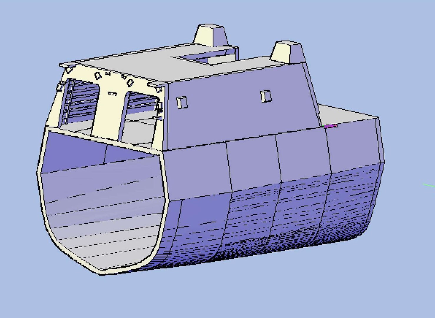 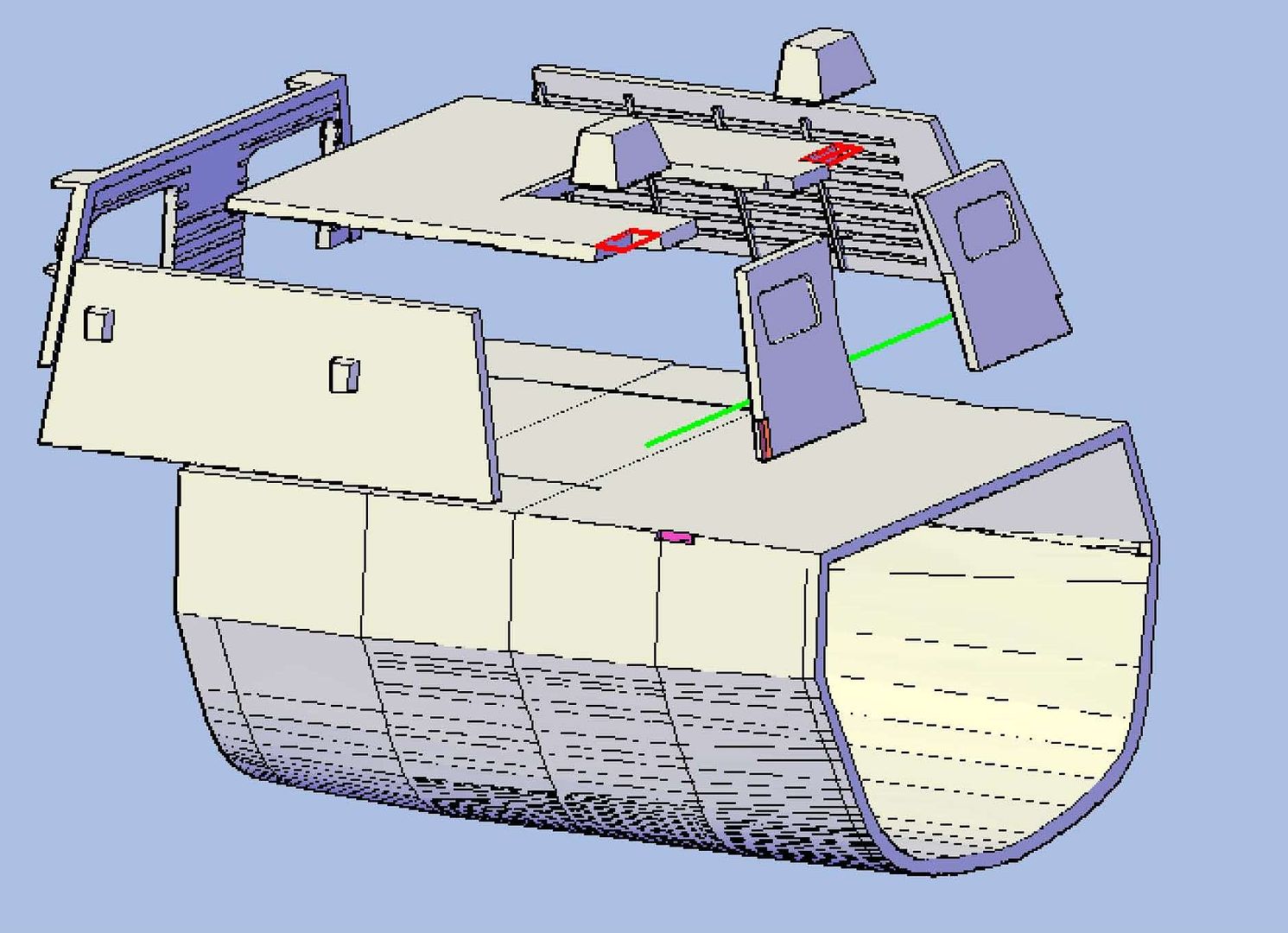 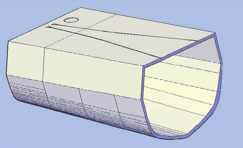 As for your question about PE, the answer is yes. I don’t know how much I will get to do on Bertholf until Friday, as I am making a sampling run to eastern Oklahoma. CHEERS!!! Funny you should ask Brian.
As a matter of fact I have been e-mailing with Pavel about that very thing. Here are some images that best answer your question about sections. The first image shows the Hangar and “Part C - Hull-Hangar-StackHouse”. It is the third of five, possibly six hull segments, (Connections have not been made.) The second image shows the hangar split into the parts that will be printed. It went from one part to eight. The last image is “Part B - Hull-Helo Deck”. The only other completed hull section, “Part A - Hull-Fantail” has previously been shown.
[url=http://s1352.photobucket.com/user/rdutnell/media/USCG%20Cutter%20%20-%20Bertholf/USCGCutter-52-pix-b_Page_1_zps53d0f4f1.jpg.html][img]http://i1352.photobucket.com/albums/q659/rdutnell/USCG%20Cutter%20%20-%20Bertholf/USCGCutter-52-pix-b_Page_1_zps53d0f4f1.jpg[/img][/url]
[url=http://s1352.photobucket.com/user/rdutnell/media/USCG%20Cutter%20%20-%20Bertholf/USCGCutter-52-pix-b_Page_2_zpse523d19d.jpg.html][img]http://i1352.photobucket.com/albums/q659/rdutnell/USCG%20Cutter%20%20-%20Bertholf/USCGCutter-52-pix-b_Page_2_zpse523d19d.jpg[/img][/url]
[url=http://s1352.photobucket.com/user/rdutnell/media/USCG%20Cutter%20%20-%20Bertholf/USCGCutter-52-pix-b_Page_3_zpscedccae9.jpg.html][img]http://i1352.photobucket.com/albums/q659/rdutnell/USCG%20Cutter%20%20-%20Bertholf/USCGCutter-52-pix-b_Page_3_zpscedccae9.jpg[/img][/url]
As for your question about PE, the answer is yes.
I don’t know how much I will get to do on Bertholf until Friday, as I am making a sampling run to eastern Oklahoma.
CHEERS!!!
|
|
|
|
Posted: Tue Jul 23, 2013 12:42 pm |
|
|
|
|
|
| |
Post subject: |
Re: USCGC Bertholf (WMSL-750) – A CAD Design for 3D Printing |
|
|
|
When you are modeling this are you planning how the secetions will break down for printing/casting or are you worrying about that later? Also are you going to model the parts that will be done in PE?
When you are modeling this are you planning how the secetions will break down for printing/casting or are you worrying about that later? Also are you going to model the parts that will be done in PE?
|
|
|
|
Posted: Tue Jul 23, 2013 11:46 am |
|
|
|
|
|
| |
Post subject: |
Re: USCGC Bertholf (WMSL-750) – A CAD Design for 3D Printing |
|
|
UPDATE 52Good Morning All! I didn’t get a lot done yesterday, at least that can be seen, but I did complete the detailing on the top of the stack, except for the RQAWT scuttle, that I don’t know what looks like. I had previously traced the objects on the plans and moved them to the model… 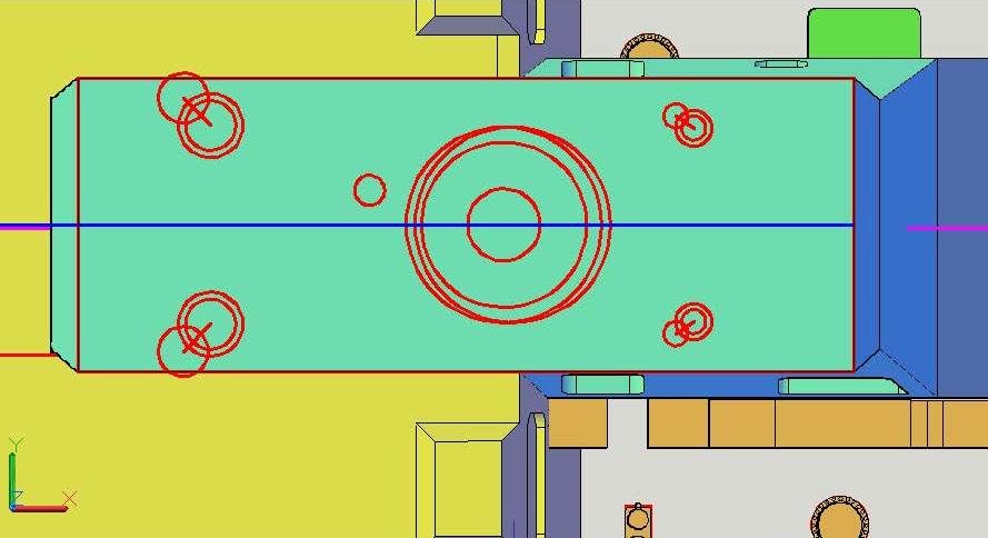 …So I started with the Gas Turbine Exhaust. I extended the line between the lower sections up and drew a circle with the same diameter as the one traced from the plans on the end of it. 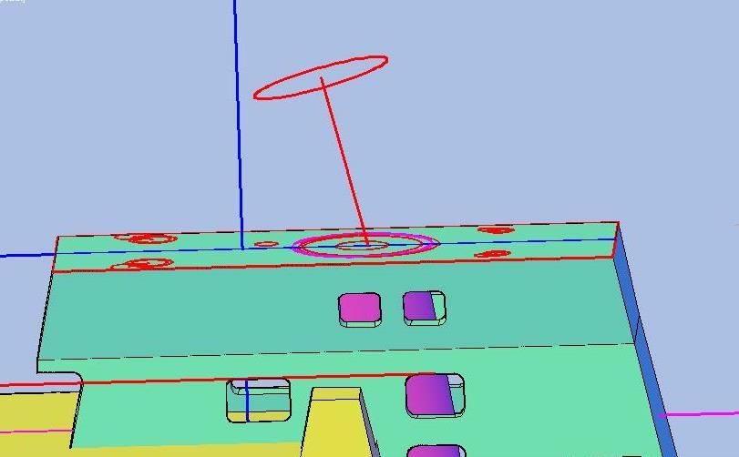 I extruded this circle well into the top of the stack house… 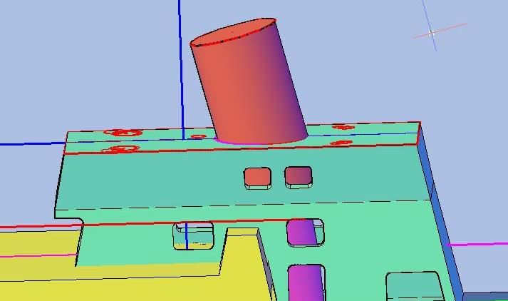 …And sliced it perpendicular to match the pictures I have of it. 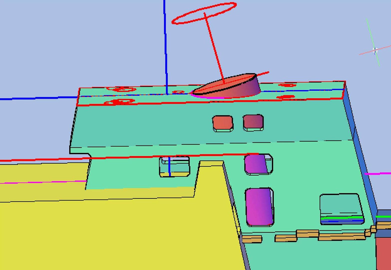 I then sliced it at the top of the deck level. 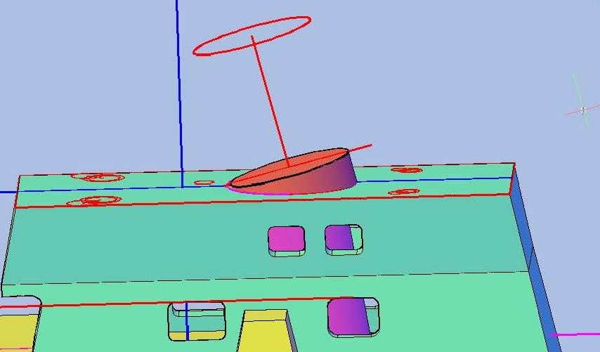 With the base complete, I started on the pipe part. To do this I copied the original (red) circle down and resized it to match the plans (green), then copied it down to what I thought looked to be the right height above the base and extruded it into the base. 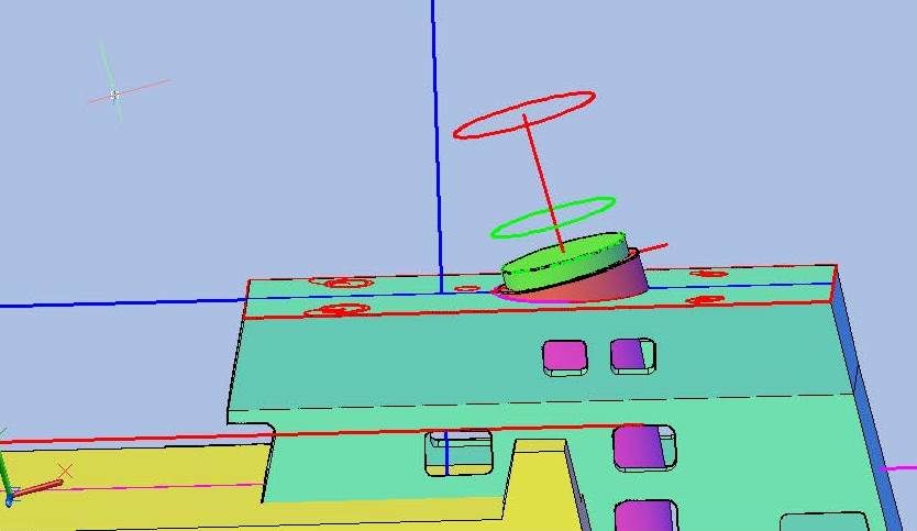 Next I made a circle the size of ID of the pipe and extruded it through the other two parts. 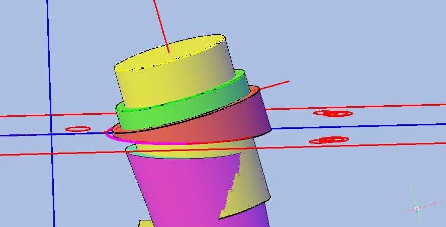 I then subtracted it from the two parts. 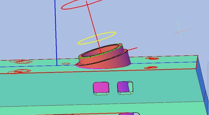 Although I don’t show it I then subtracted another set of extruded circles so that the wall thickness of the pipe goes from 0.025” at the base to 0.010” at the end. 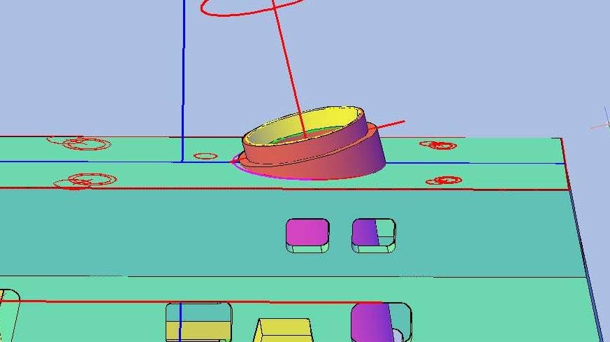 Next, I extruded the pipe through the top of the house and subtracted it. In the image below I turned off the stack layer so the cut may be seen. 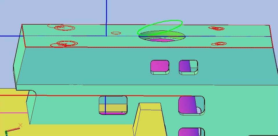 And here are a couple of shots of it with the stack layer turned back on.   I started on the MPDE Exhaust vents next. To begin, I moved all of the traced circles and lines up 0.025” and extruded the outer circle into the top of the house. I do it this way because sometimes items that appear to be on the surface are not, and in fact are up a very small amount, which can throw things off. If I extrude it into the hull and slice it at the hull, it assures that it is in contact with the surface.  After reorienting my coordinate system, I drew a polyline up from the center of the circle then angled along the axis of the line traced from the plans, and filleted the polyline. I then extruded the inner circle, using the polyline as the path, and drew a smaller circle for the ID. 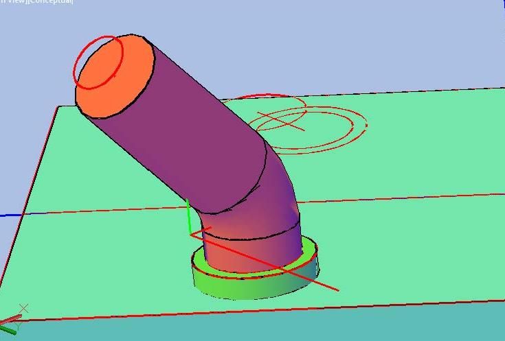 I extruded the circle to the elbow… 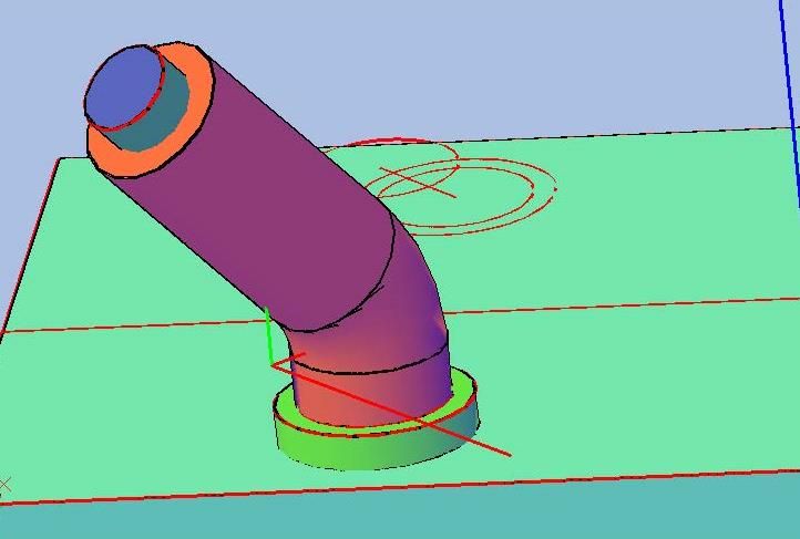 …And subtracted it. The OD of the pipe is 0.104” diameter, and the ID is 0.064”, so the wall thickness is 0.02”. 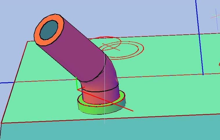 Next I sliced the end pipe along the line traced from the plans. 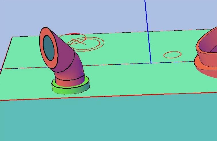 I then joined everything together and mirrored it to the other side. 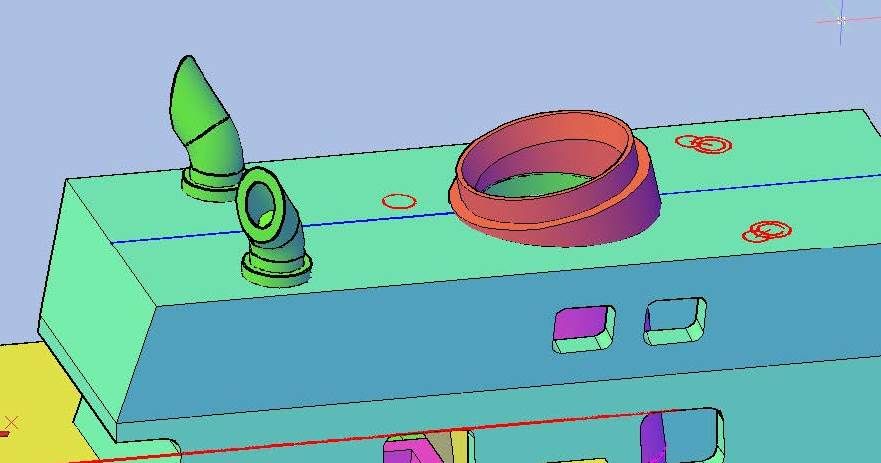 Next, I did the Incinerator Exhaust using the same methods as described for the MPDE Exhausts. The OD is 0.050” and the ID is 0.025” so the wall thickness is 0.0125”. 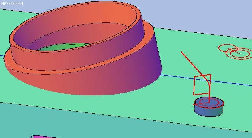 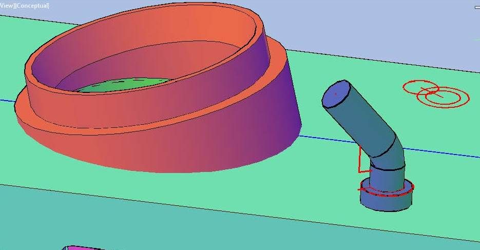 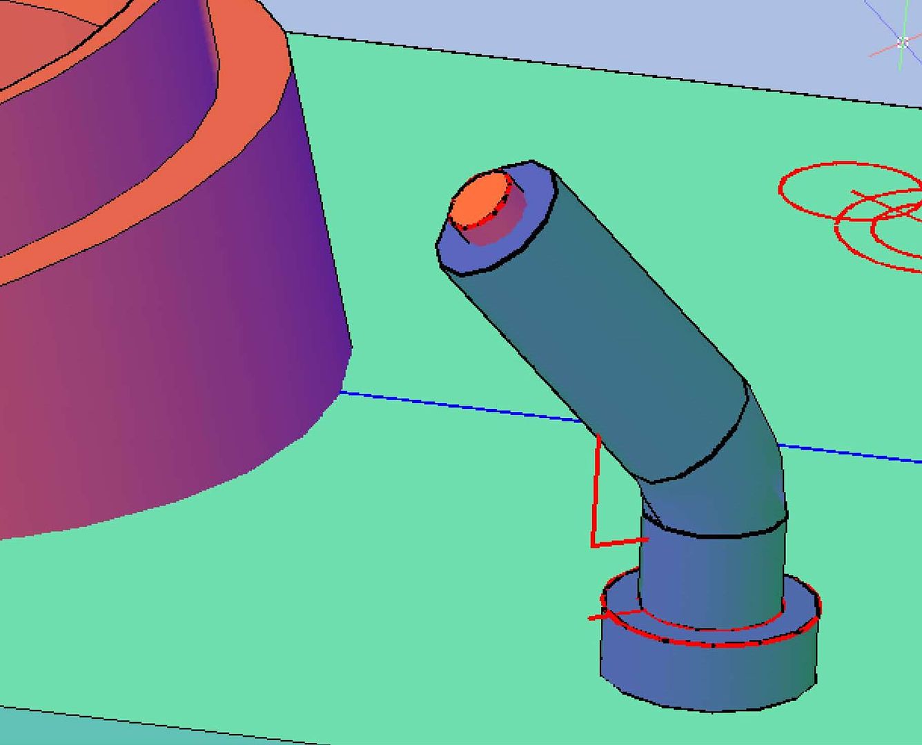 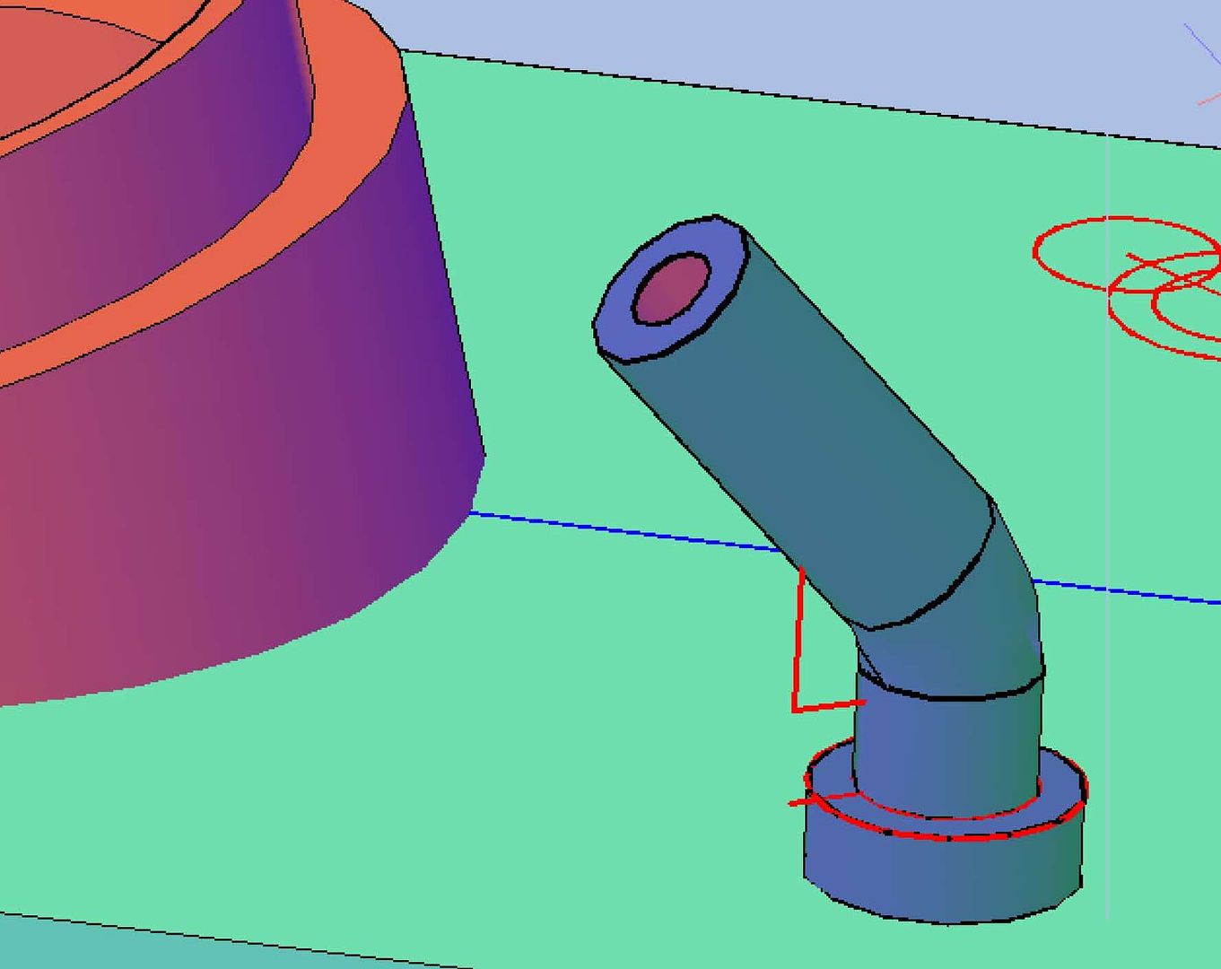 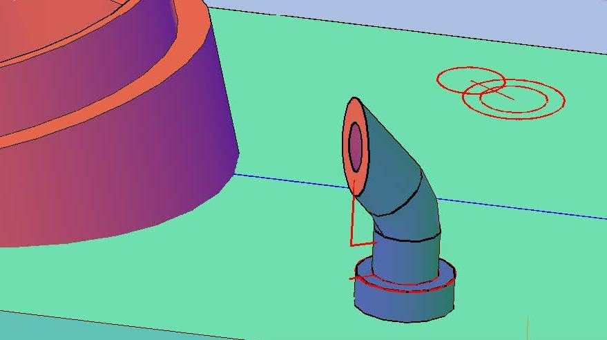 The plans show that the exhaust pipe on the port side is the SSDG No 2 Exhaust, but in pictures it looks the same as the Incinerator Exhaust, so I mirrored it. 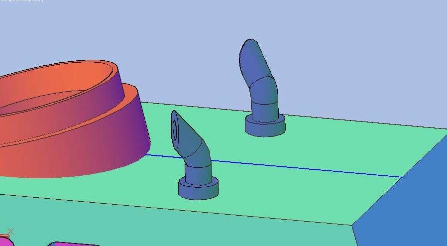 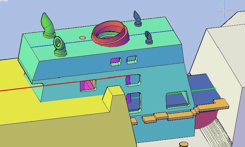 So the top is as complete as I can get it until I find out what the RQAWT scuttle looks like. CHEERS!!!
[u][b]UPDATE 52[/b][/u]
Good Morning All! :wave_1:
I didn’t get a lot done yesterday, at least that can be seen, but I did complete the detailing on the top of the stack, except for the RQAWT scuttle, that I don’t know what looks like. I had previously traced the objects on the plans and moved them to the model…
[url=http://s1352.photobucket.com/user/rdutnell/media/USCG%20Cutter%20%20-%20Bertholf/USCGCutter-52-pix_Page_01_zps069c2b79.jpg.html][img]http://i1352.photobucket.com/albums/q659/rdutnell/USCG%20Cutter%20%20-%20Bertholf/USCGCutter-52-pix_Page_01_zps069c2b79.jpg[/img][/url]
…So I started with the Gas Turbine Exhaust. I extended the line between the lower sections up and drew a circle with the same diameter as the one traced from the plans on the end of it.
[url=http://s1352.photobucket.com/user/rdutnell/media/USCG%20Cutter%20%20-%20Bertholf/USCGCutter-52-pix_Page_02_zpsc813c7ec.jpg.html][img]http://i1352.photobucket.com/albums/q659/rdutnell/USCG%20Cutter%20%20-%20Bertholf/USCGCutter-52-pix_Page_02_zpsc813c7ec.jpg[/img][/url]
I extruded this circle well into the top of the stack house…
[url=http://s1352.photobucket.com/user/rdutnell/media/USCG%20Cutter%20%20-%20Bertholf/USCGCutter-52-pix_Page_03_zpsd58038e7.jpg.html][img]http://i1352.photobucket.com/albums/q659/rdutnell/USCG%20Cutter%20%20-%20Bertholf/USCGCutter-52-pix_Page_03_zpsd58038e7.jpg[/img][/url]
…And sliced it perpendicular to match the pictures I have of it.
[url=http://s1352.photobucket.com/user/rdutnell/media/USCG%20Cutter%20%20-%20Bertholf/USCGCutter-52-pix_Page_04_zps6f43dc66.jpg.html][img]http://i1352.photobucket.com/albums/q659/rdutnell/USCG%20Cutter%20%20-%20Bertholf/USCGCutter-52-pix_Page_04_zps6f43dc66.jpg[/img][/url]
I then sliced it at the top of the deck level.
[url=http://s1352.photobucket.com/user/rdutnell/media/USCG%20Cutter%20%20-%20Bertholf/USCGCutter-52-pix_Page_05_zpsa2dbe4d9.jpg.html][img]http://i1352.photobucket.com/albums/q659/rdutnell/USCG%20Cutter%20%20-%20Bertholf/USCGCutter-52-pix_Page_05_zpsa2dbe4d9.jpg[/img][/url]
With the base complete, I started on the pipe part. To do this I copied the original (red) circle down and resized it to match the plans (green), then copied it down to what I thought looked to be the right height above the base and extruded it into the base.
[url=http://s1352.photobucket.com/user/rdutnell/media/USCG%20Cutter%20%20-%20Bertholf/USCGCutter-52-pix_Page_06_zps89e424b4.jpg.html][img]http://i1352.photobucket.com/albums/q659/rdutnell/USCG%20Cutter%20%20-%20Bertholf/USCGCutter-52-pix_Page_06_zps89e424b4.jpg[/img][/url]
Next I made a circle the size of ID of the pipe and extruded it through the other two parts.
[url=http://s1352.photobucket.com/user/rdutnell/media/USCG%20Cutter%20%20-%20Bertholf/USCGCutter-52-pix_Page_07_zps8933133c.jpg.html][img]http://i1352.photobucket.com/albums/q659/rdutnell/USCG%20Cutter%20%20-%20Bertholf/USCGCutter-52-pix_Page_07_zps8933133c.jpg[/img][/url]
I then subtracted it from the two parts.
[url=http://s1352.photobucket.com/user/rdutnell/media/USCG%20Cutter%20%20-%20Bertholf/USCGCutter-52-pix_Page_08_zpsee20ccc8.jpg.html][img]http://i1352.photobucket.com/albums/q659/rdutnell/USCG%20Cutter%20%20-%20Bertholf/USCGCutter-52-pix_Page_08_zpsee20ccc8.jpg[/img][/url]
Although I don’t show it I then subtracted another set of extruded circles so that the wall thickness of the pipe goes from 0.025” at the base to 0.010” at the end.
[url=http://s1352.photobucket.com/user/rdutnell/media/USCG%20Cutter%20%20-%20Bertholf/USCGCutter-52-pix_Page_09_zps5137c8ec.jpg.html][img]http://i1352.photobucket.com/albums/q659/rdutnell/USCG%20Cutter%20%20-%20Bertholf/USCGCutter-52-pix_Page_09_zps5137c8ec.jpg[/img][/url]
Next, I extruded the pipe through the top of the house and subtracted it. In the image below I turned off the stack layer so the cut may be seen.
[url=http://s1352.photobucket.com/user/rdutnell/media/USCG%20Cutter%20%20-%20Bertholf/USCGCutter-52-pix_Page_10_zpsebbd9ce4.jpg.html][img]http://i1352.photobucket.com/albums/q659/rdutnell/USCG%20Cutter%20%20-%20Bertholf/USCGCutter-52-pix_Page_10_zpsebbd9ce4.jpg[/img][/url]
And here are a couple of shots of it with the stack layer turned back on.
[url=http://s1352.photobucket.com/user/rdutnell/media/USCG%20Cutter%20%20-%20Bertholf/USCGCutter-52-pix_Page_11_zps3a18a6d3.jpg.html][img]http://i1352.photobucket.com/albums/q659/rdutnell/USCG%20Cutter%20%20-%20Bertholf/USCGCutter-52-pix_Page_11_zps3a18a6d3.jpg[/img][/url]
[url=http://s1352.photobucket.com/user/rdutnell/media/USCG%20Cutter%20%20-%20Bertholf/USCGCutter-52-pix_Page_12_zpsc92cb6a0.jpg.html][img]http://i1352.photobucket.com/albums/q659/rdutnell/USCG%20Cutter%20%20-%20Bertholf/USCGCutter-52-pix_Page_12_zpsc92cb6a0.jpg[/img][/url]
I started on the MPDE Exhaust vents next. To begin, I moved all of the traced circles and lines up 0.025” and extruded the outer circle into the top of the house. I do it this way because sometimes items that appear to be on the surface are not, and in fact are up a very small amount, which can throw things off. If I extrude it into the hull and slice it at the hull, it assures that it is in contact with the surface.
[url=http://s1352.photobucket.com/user/rdutnell/media/USCG%20Cutter%20%20-%20Bertholf/USCGCutter-52-pix_Page_14_zps230ecbaf.jpg.html][img]http://i1352.photobucket.com/albums/q659/rdutnell/USCG%20Cutter%20%20-%20Bertholf/USCGCutter-52-pix_Page_14_zps230ecbaf.jpg[/img][/url]
After reorienting my coordinate system, I drew a polyline up from the center of the circle then angled along the axis of the line traced from the plans, and filleted the polyline.
[url=http://s1352.photobucket.com/user/rdutnell/media/USCG%20Cutter%20%20-%20Bertholf/USCGCutter-52-pix_Page_14_zps230ecbaf.jpg.html][img]http://i1352.photobucket.com/albums/q659/rdutnell/USCG%20Cutter%20%20-%20Bertholf/USCGCutter-52-pix_Page_14_zps230ecbaf.jpg[/img][/url]
I then extruded the inner circle, using the polyline as the path, and drew a smaller circle for the ID.
[url=http://s1352.photobucket.com/user/rdutnell/media/USCG%20Cutter%20%20-%20Bertholf/USCGCutter-52-pix_Page_15_zpsb882b57e.jpg.html][img]http://i1352.photobucket.com/albums/q659/rdutnell/USCG%20Cutter%20%20-%20Bertholf/USCGCutter-52-pix_Page_15_zpsb882b57e.jpg[/img][/url]
I extruded the circle to the elbow…
[url=http://s1352.photobucket.com/user/rdutnell/media/USCG%20Cutter%20%20-%20Bertholf/USCGCutter-52-pix_Page_16_zps871a9676.jpg.html][img]http://i1352.photobucket.com/albums/q659/rdutnell/USCG%20Cutter%20%20-%20Bertholf/USCGCutter-52-pix_Page_16_zps871a9676.jpg[/img][/url]
…And subtracted it. The OD of the pipe is 0.104” diameter, and the ID is 0.064”, so the wall thickness is 0.02”.
[url=http://s1352.photobucket.com/user/rdutnell/media/USCG%20Cutter%20%20-%20Bertholf/USCGCutter-52-pix_Page_17_zps8892ff08.jpg.html][img]http://i1352.photobucket.com/albums/q659/rdutnell/USCG%20Cutter%20%20-%20Bertholf/USCGCutter-52-pix_Page_17_zps8892ff08.jpg[/img][/url]
Next I sliced the end pipe along the line traced from the plans.
[url=http://s1352.photobucket.com/user/rdutnell/media/USCG%20Cutter%20%20-%20Bertholf/USCGCutter-52-pix_Page_18_zpsaf0584a0.jpg.html][img]http://i1352.photobucket.com/albums/q659/rdutnell/USCG%20Cutter%20%20-%20Bertholf/USCGCutter-52-pix_Page_18_zpsaf0584a0.jpg[/img][/url]
I then joined everything together and mirrored it to the other side.
[url=http://s1352.photobucket.com/user/rdutnell/media/USCG%20Cutter%20%20-%20Bertholf/USCGCutter-52-pix_Page_19_zpsd2ecea66.jpg.html][img]http://i1352.photobucket.com/albums/q659/rdutnell/USCG%20Cutter%20%20-%20Bertholf/USCGCutter-52-pix_Page_19_zpsd2ecea66.jpg[/img][/url]
Next, I did the Incinerator Exhaust using the same methods as described for the MPDE Exhausts. The OD is 0.050” and the ID is 0.025” so the wall thickness is 0.0125”.
[url=http://s1352.photobucket.com/user/rdutnell/media/USCG%20Cutter%20%20-%20Bertholf/USCGCutter-52-pix_Page_20_zpsd453ebc4.jpg.html][img]http://i1352.photobucket.com/albums/q659/rdutnell/USCG%20Cutter%20%20-%20Bertholf/USCGCutter-52-pix_Page_20_zpsd453ebc4.jpg[/img][/url]
[url=http://s1352.photobucket.com/user/rdutnell/media/USCG%20Cutter%20%20-%20Bertholf/USCGCutter-52-pix_Page_21_zps7c37a044.jpg.html][img]http://i1352.photobucket.com/albums/q659/rdutnell/USCG%20Cutter%20%20-%20Bertholf/USCGCutter-52-pix_Page_21_zps7c37a044.jpg[/img][/url]
[url=http://s1352.photobucket.com/user/rdutnell/media/USCG%20Cutter%20%20-%20Bertholf/USCGCutter-52-pix_Page_22_zps1cb2c305.jpg.html][img]http://i1352.photobucket.com/albums/q659/rdutnell/USCG%20Cutter%20%20-%20Bertholf/USCGCutter-52-pix_Page_22_zps1cb2c305.jpg[/img][/url]
[url=http://s1352.photobucket.com/user/rdutnell/media/USCG%20Cutter%20%20-%20Bertholf/USCGCutter-52-pix_Page_23_zpsf802be44.jpg.html][img]http://i1352.photobucket.com/albums/q659/rdutnell/USCG%20Cutter%20%20-%20Bertholf/USCGCutter-52-pix_Page_23_zpsf802be44.jpg[/img][/url]
[url=http://s1352.photobucket.com/user/rdutnell/media/USCG%20Cutter%20%20-%20Bertholf/USCGCutter-52-pix_Page_24_zps67794b1b.jpg.html][img]http://i1352.photobucket.com/albums/q659/rdutnell/USCG%20Cutter%20%20-%20Bertholf/USCGCutter-52-pix_Page_24_zps67794b1b.jpg[/img][/url]
The plans show that the exhaust pipe on the port side is the SSDG No 2 Exhaust, but in pictures it looks the same as the Incinerator Exhaust, so I mirrored it.
[url=http://s1352.photobucket.com/user/rdutnell/media/USCG%20Cutter%20%20-%20Bertholf/USCGCutter-52-pix_Page_25_zps84d22f7a.jpg.html][img]http://i1352.photobucket.com/albums/q659/rdutnell/USCG%20Cutter%20%20-%20Bertholf/USCGCutter-52-pix_Page_25_zps84d22f7a.jpg[/img][/url]
[url=http://s1352.photobucket.com/user/rdutnell/media/USCG%20Cutter%20%20-%20Bertholf/USCGCutter-52-pix_Page_26_zpsc847f5d5.jpg.html][img]http://i1352.photobucket.com/albums/q659/rdutnell/USCG%20Cutter%20%20-%20Bertholf/USCGCutter-52-pix_Page_26_zpsc847f5d5.jpg[/img][/url]
So the top is as complete as I can get it until I find out what the RQAWT scuttle looks like.
CHEERS!!!
|
|
|
|
Posted: Mon Jul 22, 2013 8:56 am |
|
|
|
|
|
| |
Post subject: |
Re: USCGC Bertholf (WMSL-750) – A CAD Design for 3D Printing |
|
|
UPDATE 51Good Morning Everyone! I detailed the sides of the stack house last night adding the various vents, grills, and windows. I used these pictures to do it. Note, in the first picture, the gas turbine pipe in the interior of the house seems to be discontinuous, which I really don’t understand. I wish I knew what it looked like because the plans aren’t much help. Of course, I could always just close all of the vent holes/windows and not worry about it.  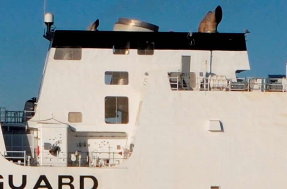 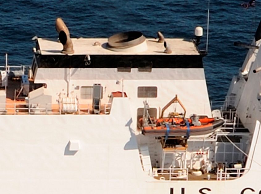 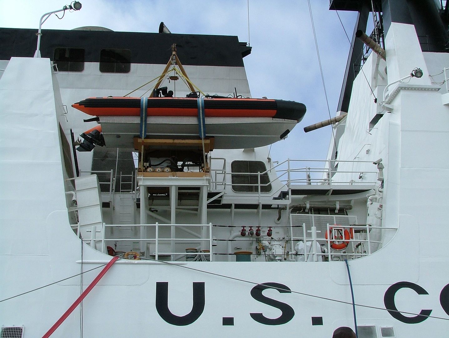 The procedure was essentially the same for all of these features. I aligned the coordinate system with the face that the feature (or features) was on and drew a rectangle to match the pictures, filleted them 0.03” and extruded them enough to penetrate the hull part (I picked 0.06”). 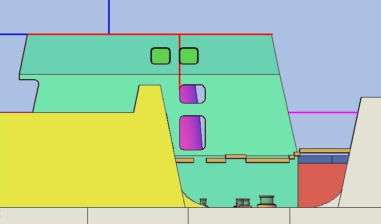 Many of the vents/windows are on both sides of the house. For features that were, like the two smaller openings near the top that I started with, I mirrored them to the other side. 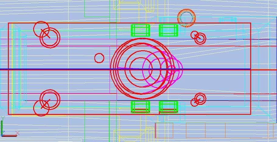 Then I subtracted them. 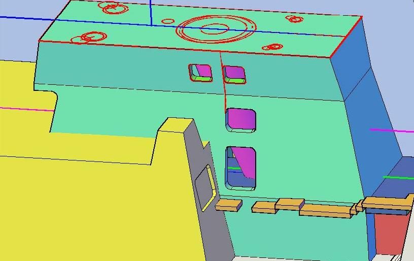  I did the larger vent window if the forward upper corner on the port side next. Sorry I didn’t clip an image after I cut it.  Next I did the window, forward, more or less adjacent to the Fan Room on both sides. 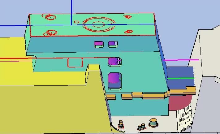  In this image you can see the window on the port side, as well as the vent previously cut.  Next I cut out the opening in the forward lower corner on the port side.  The only picture I have of the aft end isn’t good enough to go on and I don’t have any pictures of the forward side at the moment, so I’m going to put that off and do the top next. It should be fun because I know exactly what it looks like. My favorite situation is having one or two key dimensions and good pictures, which is exactly what I have for the top. CHEERS!!!
[u][b]UPDATE 51[/b][/u]
Good Morning Everyone! :wave_1:
I detailed the sides of the stack house last night adding the various vents, grills, and windows. I used these pictures to do it. Note, in the first picture, the gas turbine pipe in the interior of the house seems to be discontinuous, which I really don’t understand. I wish I knew what it looked like because the plans aren’t much help. Of course, I could always just close all of the vent holes/windows and not worry about it. :cool_2:
[url=http://s1352.photobucket.com/user/rdutnell/media/USCG%20Cutter%20%20-%20Bertholf/StackHouse-PortSide_zpsbd30fe86.jpg.html][img]http://i1352.photobucket.com/albums/q659/rdutnell/USCG%20Cutter%20%20-%20Bertholf/StackHouse-PortSide_zpsbd30fe86.jpg[/img][/url]
[url=http://s1352.photobucket.com/user/rdutnell/media/USCG%20Cutter%20%20-%20Bertholf/StackHouse-StbdSide_zps65b669e3.jpg.html][img]http://i1352.photobucket.com/albums/q659/rdutnell/USCG%20Cutter%20%20-%20Bertholf/StackHouse-StbdSide_zps65b669e3.jpg[/img][/url]
[url=http://s1352.photobucket.com/user/rdutnell/media/USCG%20Cutter%20%20-%20Bertholf/StackHouse-SRP_zps24aa8101.jpg.html][img]http://i1352.photobucket.com/albums/q659/rdutnell/USCG%20Cutter%20%20-%20Bertholf/StackHouse-SRP_zps24aa8101.jpg[/img][/url]
The procedure was essentially the same for all of these features. I aligned the coordinate system with the face that the feature (or features) was on and drew a rectangle to match the pictures, filleted them 0.03” and extruded them enough to penetrate the hull part (I picked 0.06”).
[url=http://s1352.photobucket.com/user/rdutnell/media/USCG%20Cutter%20%20-%20Bertholf/USCGCutter-51-pix_Page_01_zps2862ac2b.jpg.html][img]http://i1352.photobucket.com/albums/q659/rdutnell/USCG%20Cutter%20%20-%20Bertholf/USCGCutter-51-pix_Page_01_zps2862ac2b.jpg[/img][/url]
Many of the vents/windows are on both sides of the house. For features that were, like the two smaller openings near the top that I started with, I mirrored them to the other side.
[url=http://s1352.photobucket.com/user/rdutnell/media/USCG%20Cutter%20%20-%20Bertholf/USCGCutter-51-pix_Page_02_zps59b85d0d.jpg.html][img]http://i1352.photobucket.com/albums/q659/rdutnell/USCG%20Cutter%20%20-%20Bertholf/USCGCutter-51-pix_Page_02_zps59b85d0d.jpg[/img][/url]
Then I subtracted them.
[url=http://s1352.photobucket.com/user/rdutnell/media/USCG%20Cutter%20%20-%20Bertholf/USCGCutter-51-pix_Page_03_zps6f9a90f5.jpg.html][img]http://i1352.photobucket.com/albums/q659/rdutnell/USCG%20Cutter%20%20-%20Bertholf/USCGCutter-51-pix_Page_03_zps6f9a90f5.jpg[/img][/url]
[url=http://s1352.photobucket.com/user/rdutnell/media/USCG%20Cutter%20%20-%20Bertholf/USCGCutter-51-pix_Page_04_zps8b246bed.jpg.html][img]http://i1352.photobucket.com/albums/q659/rdutnell/USCG%20Cutter%20%20-%20Bertholf/USCGCutter-51-pix_Page_04_zps8b246bed.jpg[/img][/url]
I did the larger vent window if the forward upper corner on the port side next. Sorry I didn’t clip an image after I cut it.
[url=http://s1352.photobucket.com/user/rdutnell/media/USCG%20Cutter%20%20-%20Bertholf/USCGCutter-51-pix_Page_05_zps01b11fbf.jpg.html][img]http://i1352.photobucket.com/albums/q659/rdutnell/USCG%20Cutter%20%20-%20Bertholf/USCGCutter-51-pix_Page_05_zps01b11fbf.jpg[/img][/url]
Next I did the window, forward, more or less adjacent to the Fan Room on both sides.
[url=http://s1352.photobucket.com/user/rdutnell/media/USCG%20Cutter%20%20-%20Bertholf/USCGCutter-51-pix_Page_06_zpsd769e3dc.jpg.html][img]http://i1352.photobucket.com/albums/q659/rdutnell/USCG%20Cutter%20%20-%20Bertholf/USCGCutter-51-pix_Page_06_zpsd769e3dc.jpg[/img][/url]
[url=http://s1352.photobucket.com/user/rdutnell/media/USCG%20Cutter%20%20-%20Bertholf/USCGCutter-51-pix_Page_07_zpsd471288a.jpg.html][img]http://i1352.photobucket.com/albums/q659/rdutnell/USCG%20Cutter%20%20-%20Bertholf/USCGCutter-51-pix_Page_07_zpsd471288a.jpg[/img][/url]
In this image you can see the window on the port side, as well as the vent previously cut.
[url=http://s1352.photobucket.com/user/rdutnell/media/USCG%20Cutter%20%20-%20Bertholf/USCGCutter-51-pix_Page_08_zps14ba9f69.jpg.html][img]http://i1352.photobucket.com/albums/q659/rdutnell/USCG%20Cutter%20%20-%20Bertholf/USCGCutter-51-pix_Page_08_zps14ba9f69.jpg[/img][/url]
Next I cut out the opening in the forward lower corner on the port side.
[url=http://s1352.photobucket.com/user/rdutnell/media/USCG%20Cutter%20%20-%20Bertholf/USCGCutter-51-pix_Page_09_zps83ecda22.jpg.html][img]http://i1352.photobucket.com/albums/q659/rdutnell/USCG%20Cutter%20%20-%20Bertholf/USCGCutter-51-pix_Page_09_zps83ecda22.jpg[/img][/url]
The only picture I have of the aft end isn’t good enough to go on and I don’t have any pictures of the forward side at the moment, so I’m going to put that off and do the top next. It should be fun because I know exactly what it looks like. My favorite situation is having one or two key dimensions and good pictures, which is exactly what I have for the top.
CHEERS!!!
|
|
|
|
Posted: Sun Jul 21, 2013 9:45 am |
|
|
|
|
|
| |
Post subject: |
Re: USCGC Bertholf (WMSL-750) – A CAD Design for 3D Printing |
|
|
UPDATE 50Greetings Everyone! This afternoon I switched my attention to the other side of the ship to do the SRP platforms and a few other items. Starting as I often do, with the plans, I traced the outlines of the various platforms… 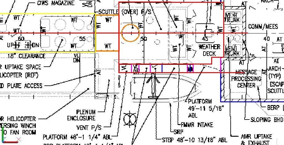 …And copied them to the model. At this point, I noted the heights ABL, and using a spreadsheet I have set up for the purpose, converted these real dimensions to 1/350 scale, and moved the platforms to their corresponding heights. 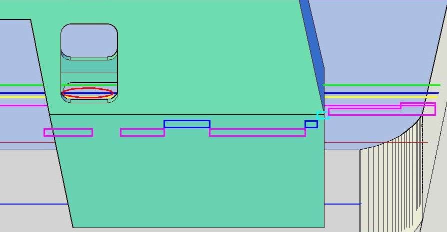 I then extruded all of the platforms down 0.025”.  Before I forgot to do it, I cutout the Fan Room vent on the starboard side. If I would have been paying attention I would have done it the same time I did the port side vent. In any case, since I save my construction lines I simply mirrored the shape from the port side…  …To the starboard side, extruded it 0.020” into the hangar, and subtracted it. 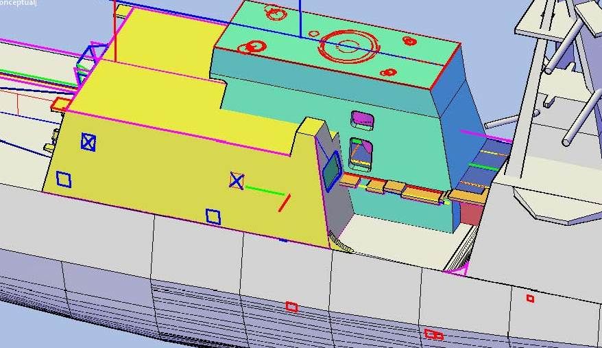 Next I decided to add the 1” Double Bitts and Capstone, shown in the plans, to the deck. First, I traced their locations from the plans… 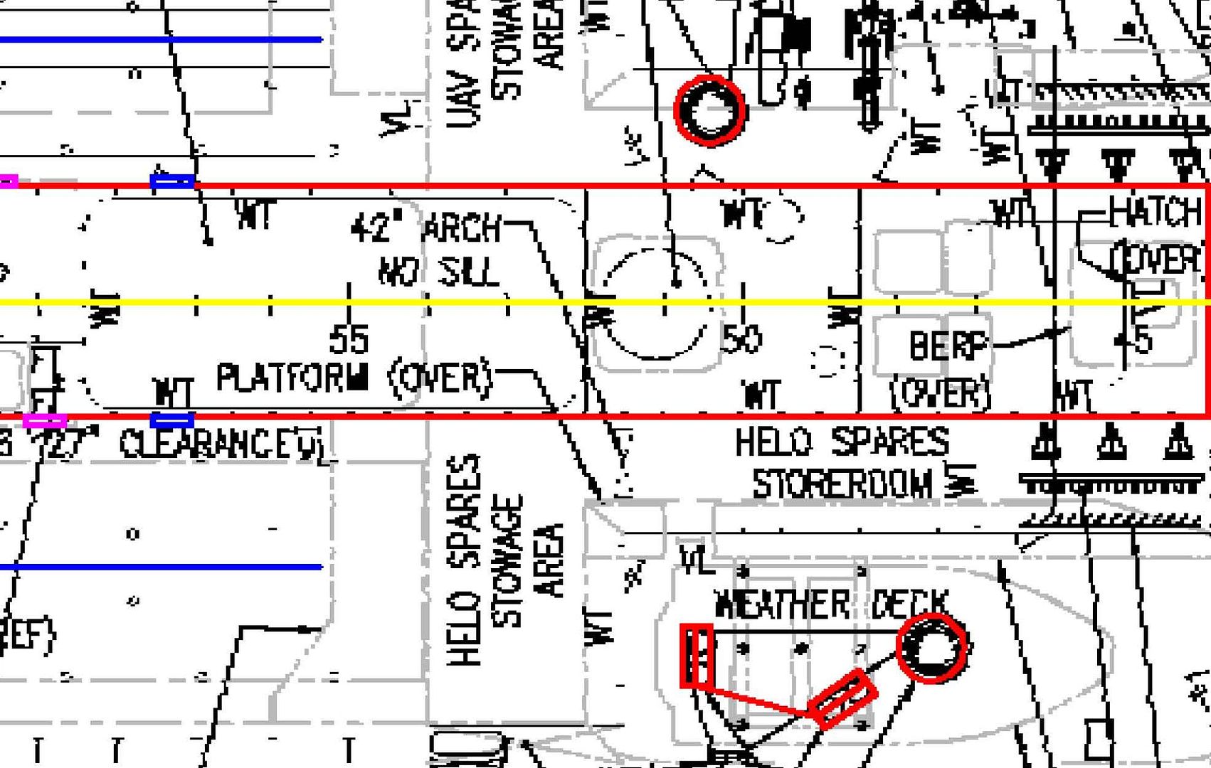 …Then copied the outlines to the plans. 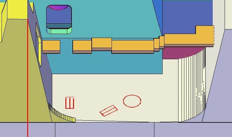 At this point I opened the 10” Double Bitt file, oriented my coordinate system square with one of the bitts and copied the bitt to the model. I then repeated the step for the other bitt. 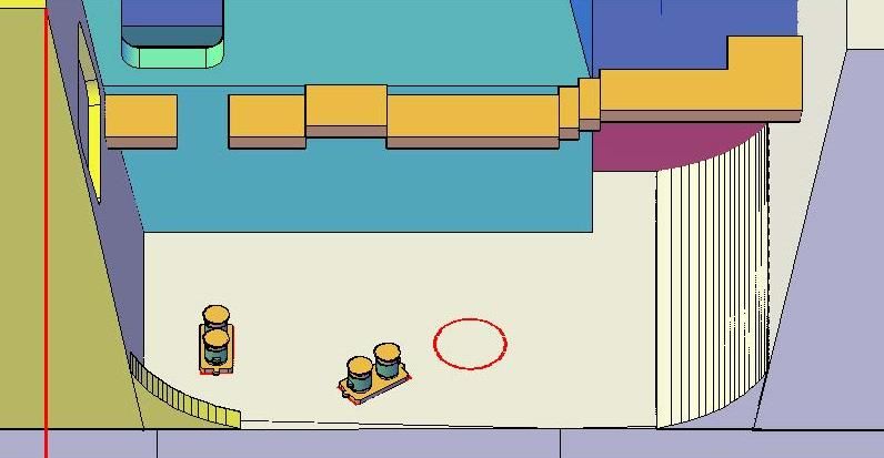 Next I opened the capstone drawing and copied it, using the center of the circle as reference. 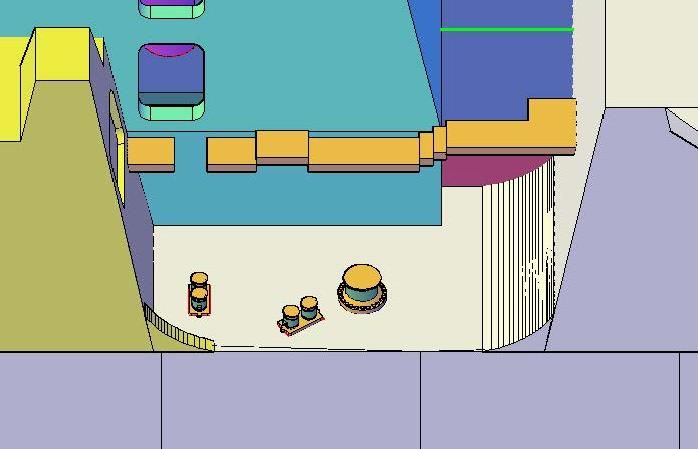 When I copied the 10” double bitts to the port side yesterday, I suspected that the unidentified round object shown on the plans was a capstone, but I wasn’t sure, so I didn’t add it. I am now sure that is what it is, so I went ahead and added the capstone to the port side too, while I had the file open. 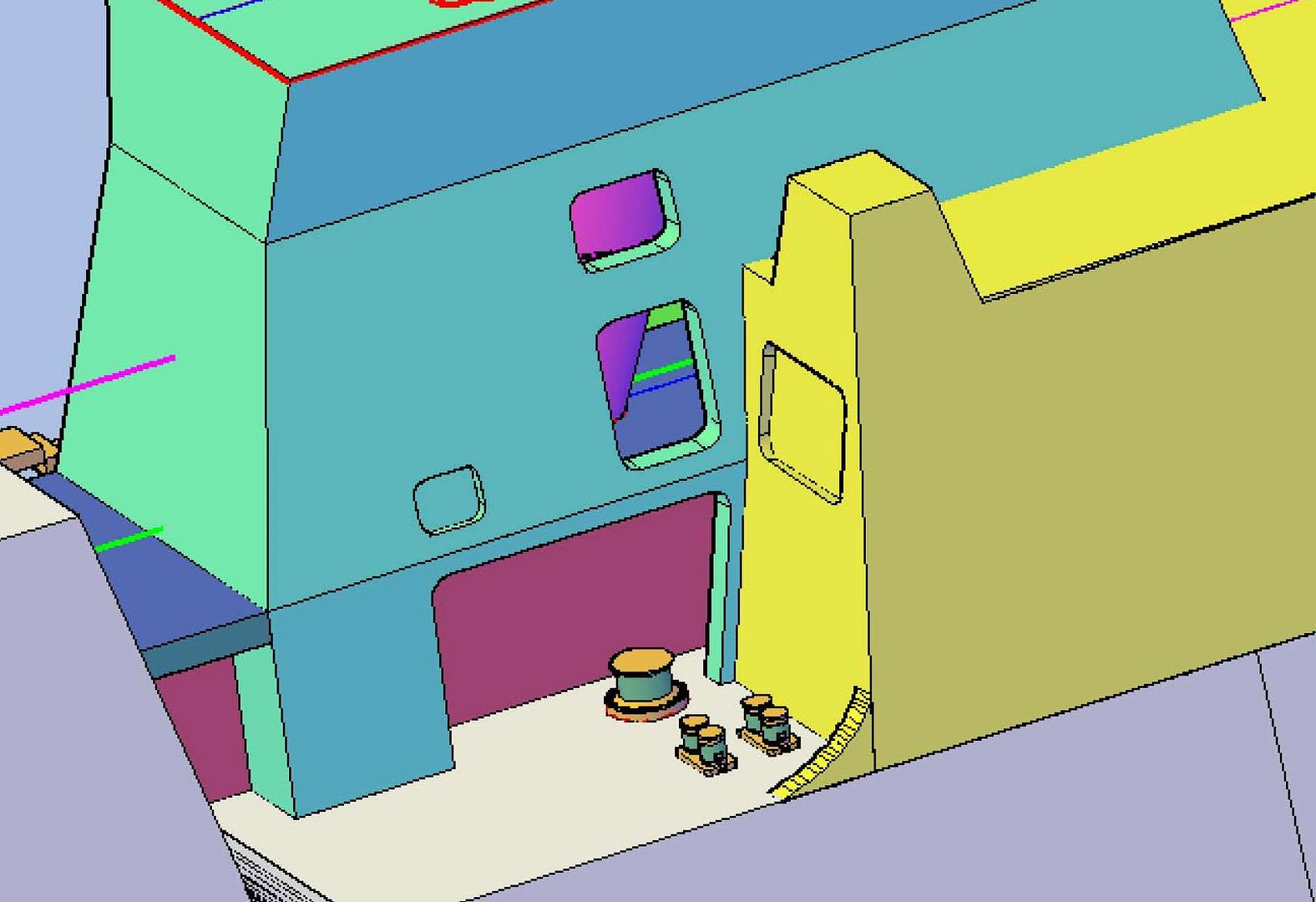 Both of these areas will need revisiting, but I have too much uncertainty at the moment to continue, so I decided to move on to other more obvious things for the time being. So, tonight I am going to continue detailing the stack house. CHEERS!!!
[u][b]UPDATE 50[/b][/u]
Greetings Everyone! :wave_1:
This afternoon I switched my attention to the other side of the ship to do the SRP platforms and a few other items. Starting as I often do, with the plans, I traced the outlines of the various platforms…
[url=http://s1352.photobucket.com/user/rdutnell/media/USCG%20Cutter%20%20-%20Bertholf/USCGCutter-50-pix_Page_01_zpsc16c49b1.jpg.html][img]http://i1352.photobucket.com/albums/q659/rdutnell/USCG%20Cutter%20%20-%20Bertholf/USCGCutter-50-pix_Page_01_zpsc16c49b1.jpg[/img][/url]
…And copied them to the model.
At this point, I noted the heights ABL, and using a spreadsheet I have set up for the purpose, converted these real dimensions to 1/350 scale, and moved the platforms to their corresponding heights.
[url=http://s1352.photobucket.com/user/rdutnell/media/USCG%20Cutter%20%20-%20Bertholf/USCGCutter-50-pix_Page_03_zps931a3f9a.jpg.html][img]http://i1352.photobucket.com/albums/q659/rdutnell/USCG%20Cutter%20%20-%20Bertholf/USCGCutter-50-pix_Page_03_zps931a3f9a.jpg[/img][/url]
I then extruded all of the platforms down 0.025”.
[url=http://s1352.photobucket.com/user/rdutnell/media/USCG%20Cutter%20%20-%20Bertholf/USCGCutter-50-pix_Page_04_zpse73a34d4.jpg.html][img]http://i1352.photobucket.com/albums/q659/rdutnell/USCG%20Cutter%20%20-%20Bertholf/USCGCutter-50-pix_Page_04_zpse73a34d4.jpg[/img][/url]
Before I forgot to do it, I cutout the Fan Room vent on the starboard side. If I would have been paying attention I would have done it the same time I did the port side vent. In any case, since I save my construction lines I simply mirrored the shape from the port side…
[url=http://s1352.photobucket.com/user/rdutnell/media/USCG%20Cutter%20%20-%20Bertholf/USCGCutter-50-pix_Page_05_zpsa4930a57.jpg.html][img]http://i1352.photobucket.com/albums/q659/rdutnell/USCG%20Cutter%20%20-%20Bertholf/USCGCutter-50-pix_Page_05_zpsa4930a57.jpg[/img][/url]
…To the starboard side, extruded it 0.020” into the hangar, and subtracted it.
[url=http://s1352.photobucket.com/user/rdutnell/media/USCG%20Cutter%20%20-%20Bertholf/USCGCutter-50-pix_Page_06_zps6ebcc32f.jpg.html][img]http://i1352.photobucket.com/albums/q659/rdutnell/USCG%20Cutter%20%20-%20Bertholf/USCGCutter-50-pix_Page_06_zps6ebcc32f.jpg[/img][/url]
Next I decided to add the 1” Double Bitts and Capstone, shown in the plans, to the deck. First, I traced their locations from the plans…
[url=http://s1352.photobucket.com/user/rdutnell/media/USCG%20Cutter%20%20-%20Bertholf/USCGCutter-50-pix_Page_07_zpse4d62a6a.jpg.html][img]http://i1352.photobucket.com/albums/q659/rdutnell/USCG%20Cutter%20%20-%20Bertholf/USCGCutter-50-pix_Page_07_zpse4d62a6a.jpg[/img][/url]
…Then copied the outlines to the plans.
[url=http://s1352.photobucket.com/user/rdutnell/media/USCG%20Cutter%20%20-%20Bertholf/USCGCutter-50-pix_Page_08_zpsdfe62565.jpg.html][img]http://i1352.photobucket.com/albums/q659/rdutnell/USCG%20Cutter%20%20-%20Bertholf/USCGCutter-50-pix_Page_08_zpsdfe62565.jpg[/img][/url]
At this point I opened the 10” Double Bitt file, oriented my coordinate system square with one of the bitts and copied the bitt to the model. I then repeated the step for the other bitt.
[url=http://s1352.photobucket.com/user/rdutnell/media/USCG%20Cutter%20%20-%20Bertholf/USCGCutter-50-pix_Page_09_zps2a907fdf.jpg.html][img]http://i1352.photobucket.com/albums/q659/rdutnell/USCG%20Cutter%20%20-%20Bertholf/USCGCutter-50-pix_Page_09_zps2a907fdf.jpg[/img][/url]
Next I opened the capstone drawing and copied it, using the center of the circle as reference.
[url=http://s1352.photobucket.com/user/rdutnell/media/USCG%20Cutter%20%20-%20Bertholf/USCGCutter-50-pix_Page_10_zps4cd3a389.jpg.html][img]http://i1352.photobucket.com/albums/q659/rdutnell/USCG%20Cutter%20%20-%20Bertholf/USCGCutter-50-pix_Page_10_zps4cd3a389.jpg[/img][/url]
When I copied the 10” double bitts to the port side yesterday, I suspected that the unidentified round object shown on the plans was a capstone, but I wasn’t sure, so I didn’t add it. I am now sure that is what it is, so I went ahead and added the capstone to the port side too, while I had the file open.
[url=http://s1352.photobucket.com/user/rdutnell/media/USCG%20Cutter%20%20-%20Bertholf/USCGCutter-50-pix_Page_11_zps4555a48b.jpg.html][img]http://i1352.photobucket.com/albums/q659/rdutnell/USCG%20Cutter%20%20-%20Bertholf/USCGCutter-50-pix_Page_11_zps4555a48b.jpg[/img][/url]
Both of these areas will need revisiting, but I have too much uncertainty at the moment to continue, so I decided to move on to other more obvious things for the time being. So, tonight I am going to continue detailing the stack house.
CHEERS!!!
:wave_1:
|
|
|
|
Posted: Sat Jul 20, 2013 5:10 pm |
|
|
|
|
|
| |
Post subject: |
Re: USCGC Bertholf (WMSL-750) – A CAD Design for 3D Printing |
|
|
UPDATE 49Good Morning guys! As I said in my last post, I had some corrections to make, so that is what I did last night. I changed not just the parts, but some of their names too. The first part I corrected, and the first to go on the deck in the assembly process, is Part 063-Corridor-01Level. 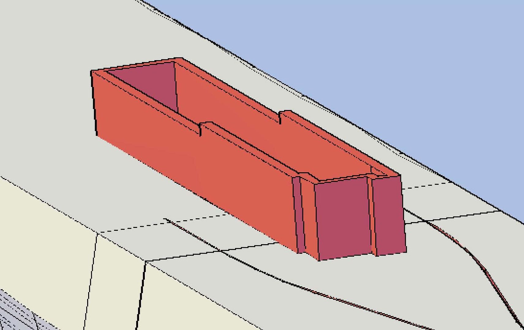 This was followed by the next part to be assembled, Part 064-Corridor-02Level-Fwd. Note that Part 063 has a cut out for Part 064 to fit in so that the top is even with the deck level. 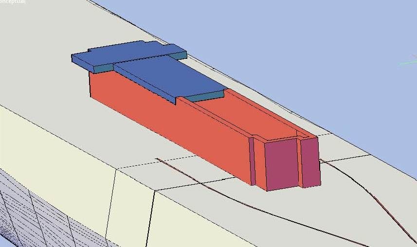 Next comes Part 065-Corridor-02Level-Aft. 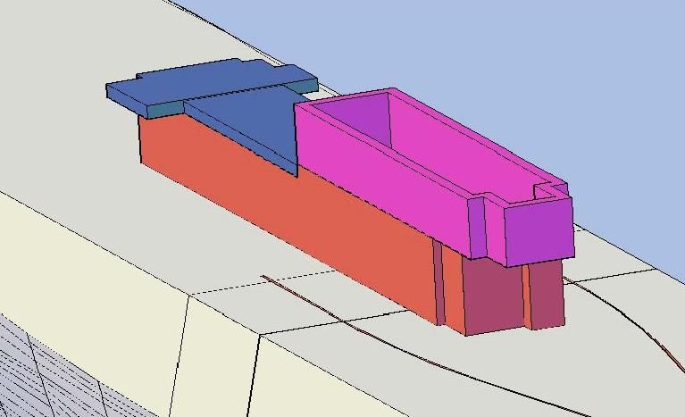 Next in the assembly process comes Part 066-Hangar-FwdBulkhead-Port and Part 067-Hangar-FwdBulkhead-Stbd. 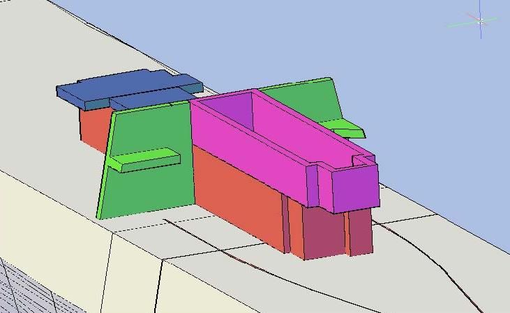 This will be followed by Part 062-Hangar. However, when I got to this point, Part 065-Corridor-02Level-Aft was protruding out the aft end of the hangar... 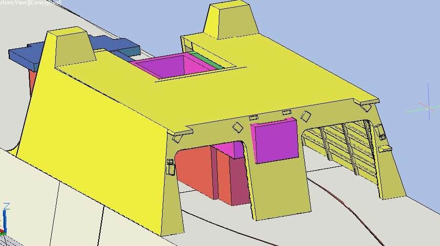 …So I sliced it along the inside edge of the aft bulkhead of the hangar. 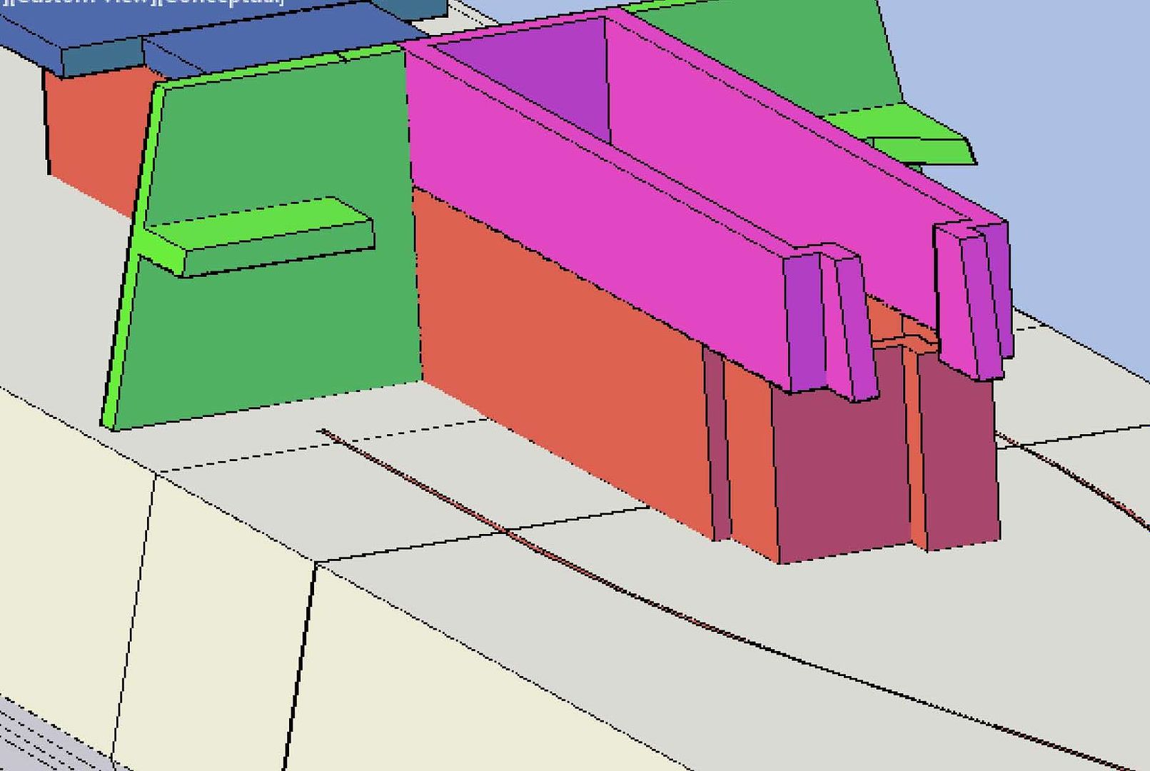 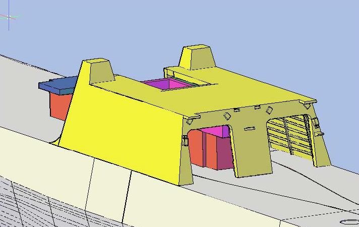 In the image below, I have added Part 069-StackHouse (Cyan) and Part 070-FAS Locker (Green). The pipe shown (blue) is incorrect and was created by extruding a circle straight up from the location shown on the plans at the 02 Level. 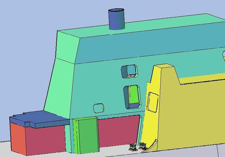 The image below shows the correction I made to the alcove just aft of the FAS Locker… 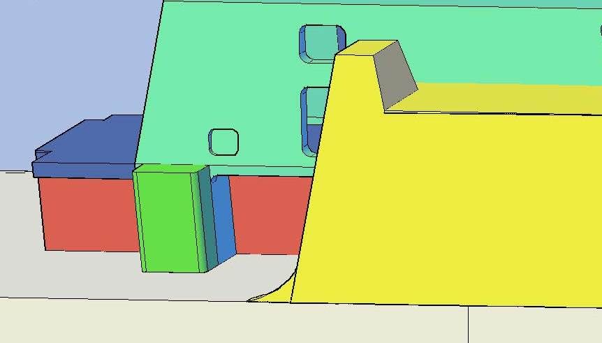 To properly locate what would become Part 068-GasTurbineExhaustPipe, I traced it from the Top of Stack drawing. While I was at it, I traced the other features as well. 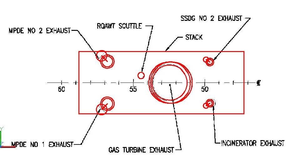 I also traced the gas turbine exhaust from the Top of house drawing… 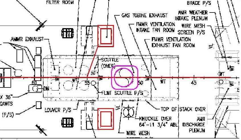 …Copied t hem to the model, positioned the circles at the correct heights… 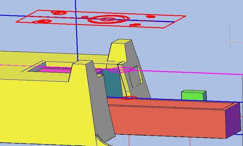 …And lofted them. 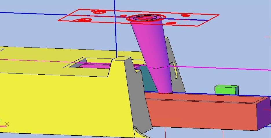 Next I copied the stack house to the side and subtracted it from the gas turbine exhaust pipe creating Part 68. 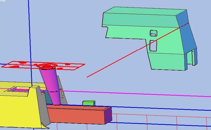 The image below shows the gas turbine exhaust pipe through the vent holes in the Stack House. 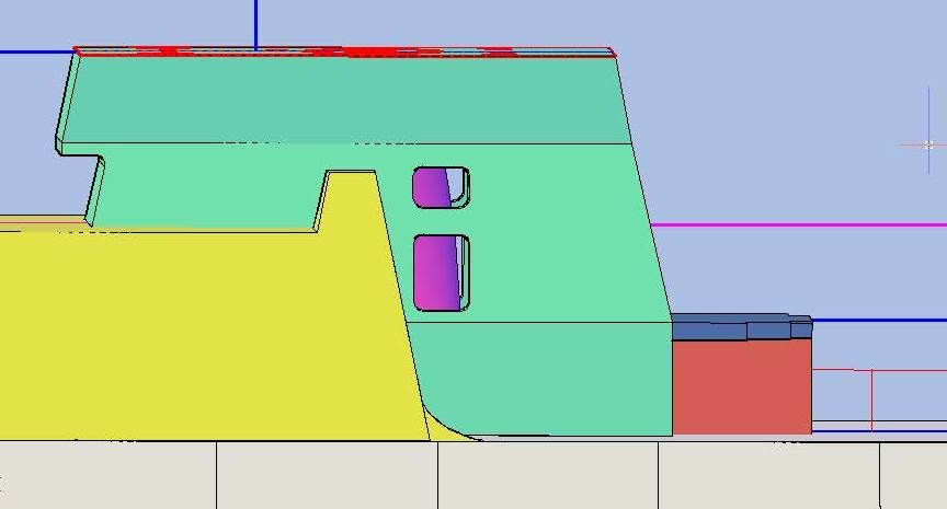 I haven’t made connections yet, both because I don’t know if the parts I have will be subdivided further, and because I don’t want to add or subtract anything from the hull/deck part until I shell it. CHEERS!!!
[u][b]UPDATE 49[/b][/u]
Good Morning guys! :wave_1:
As I said in my last post, I had some corrections to make, so that is what I did last night. I changed not just the parts, but some of their names too.
The first part I corrected, and the first to go on the deck in the assembly process, is Part 063-Corridor-01Level.
[url=http://s1352.photobucket.com/user/rdutnell/media/USCG%20Cutter%20%20-%20Bertholf/USCGCutter-49-pix_Page_01_zps4562e437.jpg.html][img]http://i1352.photobucket.com/albums/q659/rdutnell/USCG%20Cutter%20%20-%20Bertholf/USCGCutter-49-pix_Page_01_zps4562e437.jpg[/img][/url]
This was followed by the next part to be assembled, Part 064-Corridor-02Level-Fwd. Note that Part 063 has a cut out for Part 064 to fit in so that the top is even with the deck level.
[url=http://s1352.photobucket.com/user/rdutnell/media/USCG%20Cutter%20%20-%20Bertholf/USCGCutter-49-pix_Page_02_zps1e43ae03.jpg.html][img]http://i1352.photobucket.com/albums/q659/rdutnell/USCG%20Cutter%20%20-%20Bertholf/USCGCutter-49-pix_Page_02_zps1e43ae03.jpg[/img][/url]
Next comes Part 065-Corridor-02Level-Aft.
[url=http://s1352.photobucket.com/user/rdutnell/media/USCG%20Cutter%20%20-%20Bertholf/USCGCutter-49-pix_Page_03_zps763c964a.jpg.html][img]http://i1352.photobucket.com/albums/q659/rdutnell/USCG%20Cutter%20%20-%20Bertholf/USCGCutter-49-pix_Page_03_zps763c964a.jpg[/img][/url]
Next in the assembly process comes Part 066-Hangar-FwdBulkhead-Port and Part 067-Hangar-FwdBulkhead-Stbd.
[url=http://s1352.photobucket.com/user/rdutnell/media/USCG%20Cutter%20%20-%20Bertholf/USCGCutter-49-pix_Page_04_zps1767968a.jpg.html][img]http://i1352.photobucket.com/albums/q659/rdutnell/USCG%20Cutter%20%20-%20Bertholf/USCGCutter-49-pix_Page_04_zps1767968a.jpg[/img][/url]
This will be followed by Part 062-Hangar. However, when I got to this point, Part 065-Corridor-02Level-Aft was protruding out the aft end of the hangar...
[url=http://s1352.photobucket.com/user/rdutnell/media/USCG%20Cutter%20%20-%20Bertholf/USCGCutter-49-pix_Page_05_zps4fe32573.jpg.html][img]http://i1352.photobucket.com/albums/q659/rdutnell/USCG%20Cutter%20%20-%20Bertholf/USCGCutter-49-pix_Page_05_zps4fe32573.jpg[/img][/url]
…So I sliced it along the inside edge of the aft bulkhead of the hangar.
[url=http://s1352.photobucket.com/user/rdutnell/media/USCG%20Cutter%20%20-%20Bertholf/USCGCutter-49-pix_Page_07_zpsc67edcab.jpg.html][img]http://i1352.photobucket.com/albums/q659/rdutnell/USCG%20Cutter%20%20-%20Bertholf/USCGCutter-49-pix_Page_07_zpsc67edcab.jpg[/img][/url]
[url=http://s1352.photobucket.com/user/rdutnell/media/USCG%20Cutter%20%20-%20Bertholf/USCGCutter-49-pix_Page_08_zps510d539a.jpg.html][img]http://i1352.photobucket.com/albums/q659/rdutnell/USCG%20Cutter%20%20-%20Bertholf/USCGCutter-49-pix_Page_08_zps510d539a.jpg[/img][/url]
In the image below, I have added Part 069-StackHouse (Cyan) and Part 070-FAS Locker (Green). The pipe shown (blue) is incorrect and was created by extruding a circle straight up from the location shown on the plans at the 02 Level.
[url=http://s1352.photobucket.com/user/rdutnell/media/USCG%20Cutter%20%20-%20Bertholf/USCGCutter-49-pix_Page_09_zps4110b9d8.jpg.html][img]http://i1352.photobucket.com/albums/q659/rdutnell/USCG%20Cutter%20%20-%20Bertholf/USCGCutter-49-pix_Page_09_zps4110b9d8.jpg[/img][/url]
The image below shows the correction I made to the alcove just aft of the FAS Locker…
[url=http://s1352.photobucket.com/user/rdutnell/media/USCG%20Cutter%20%20-%20Bertholf/USCGCutter-49-pix_Page_11_zps2cd62fde.jpg.html][img]http://i1352.photobucket.com/albums/q659/rdutnell/USCG%20Cutter%20%20-%20Bertholf/USCGCutter-49-pix_Page_11_zps2cd62fde.jpg[/img][/url]
To properly locate what would become Part 068-GasTurbineExhaustPipe, I traced it from the Top of Stack drawing. While I was at it, I traced the other features as well.
[url=http://s1352.photobucket.com/user/rdutnell/media/USCG%20Cutter%20%20-%20Bertholf/USCGCutter-49-pix_Page_12_zps34cd7d3f.jpg.html][img]http://i1352.photobucket.com/albums/q659/rdutnell/USCG%20Cutter%20%20-%20Bertholf/USCGCutter-49-pix_Page_12_zps34cd7d3f.jpg[/img][/url]
I also traced the gas turbine exhaust from the Top of house drawing…
[url=http://s1352.photobucket.com/user/rdutnell/media/USCG%20Cutter%20%20-%20Bertholf/USCGCutter-49-pix_Page_13_zps9bf50eb5.jpg.html][img]http://i1352.photobucket.com/albums/q659/rdutnell/USCG%20Cutter%20%20-%20Bertholf/USCGCutter-49-pix_Page_13_zps9bf50eb5.jpg[/img][/url]
…Copied t hem to the model, positioned the circles at the correct heights…
[url=http://s1352.photobucket.com/user/rdutnell/media/USCG%20Cutter%20%20-%20Bertholf/USCGCutter-49-pix_Page_14_zps8c3cfaf9.jpg.html][img]http://i1352.photobucket.com/albums/q659/rdutnell/USCG%20Cutter%20%20-%20Bertholf/USCGCutter-49-pix_Page_14_zps8c3cfaf9.jpg[/img][/url]
…And lofted them.
[url=http://s1352.photobucket.com/user/rdutnell/media/USCG%20Cutter%20%20-%20Bertholf/USCGCutter-49-pix_Page_15_zps542cb920.jpg.html][img]http://i1352.photobucket.com/albums/q659/rdutnell/USCG%20Cutter%20%20-%20Bertholf/USCGCutter-49-pix_Page_15_zps542cb920.jpg[/img][/url]
Next I copied the stack house to the side and subtracted it from the gas turbine exhaust pipe creating Part 68.
[url=http://s1352.photobucket.com/user/rdutnell/media/USCG%20Cutter%20%20-%20Bertholf/USCGCutter-49-pix_Page_16_zpscac57da8.jpg.html][img]http://i1352.photobucket.com/albums/q659/rdutnell/USCG%20Cutter%20%20-%20Bertholf/USCGCutter-49-pix_Page_16_zpscac57da8.jpg[/img][/url]
The image below shows the gas turbine exhaust pipe through the vent holes in the Stack House.
[url=http://s1352.photobucket.com/user/rdutnell/media/USCG%20Cutter%20%20-%20Bertholf/USCGCutter-49-pix_Page_17_zpscdb7cf75.jpg.html][img]http://i1352.photobucket.com/albums/q659/rdutnell/USCG%20Cutter%20%20-%20Bertholf/USCGCutter-49-pix_Page_17_zpscdb7cf75.jpg[/img][/url]
I haven’t made connections yet, both because I don’t know if the parts I have will be subdivided further, and because I don’t want to add or subtract anything from the hull/deck part until I shell it.
CHEERS!!!
|
|
|
|
Posted: Sat Jul 20, 2013 11:17 am |
|
|
|
|
|
| |
Post subject: |
Re: USCGC Bertholf (WMSL-750) – A CAD Design for 3D Printing |
|
|
UPDATE 48Hi Everybody! On Bertholf, the next thing I did was add the FAS Locker, first tracing the outline of it from the plans with a polyline… 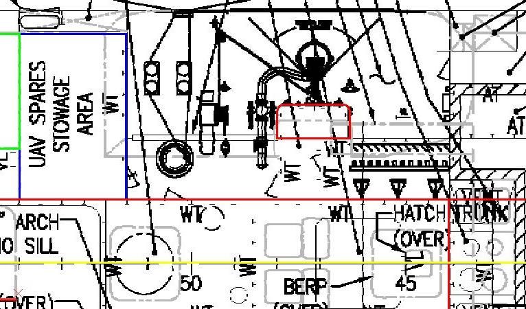 …And copying the polyline to the model. 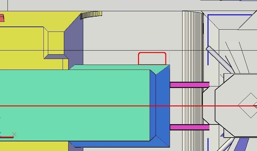 I then extruded the polyline up along the face of the exhaust stack part to the proper elevation. 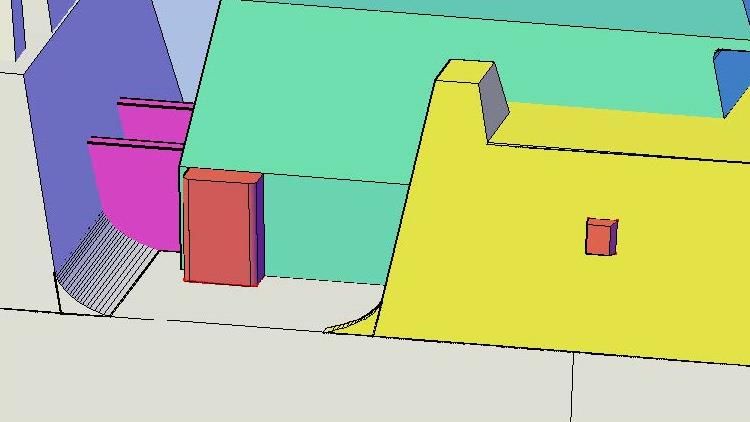 Next I referred to pictures to draw the cutout in the exhaust stack, extruding the polyline created through the part… 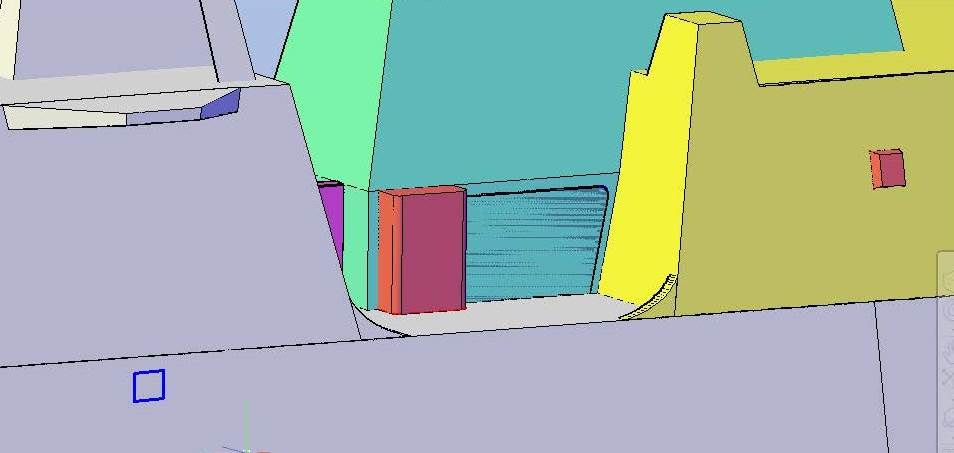 …And subtracting it. 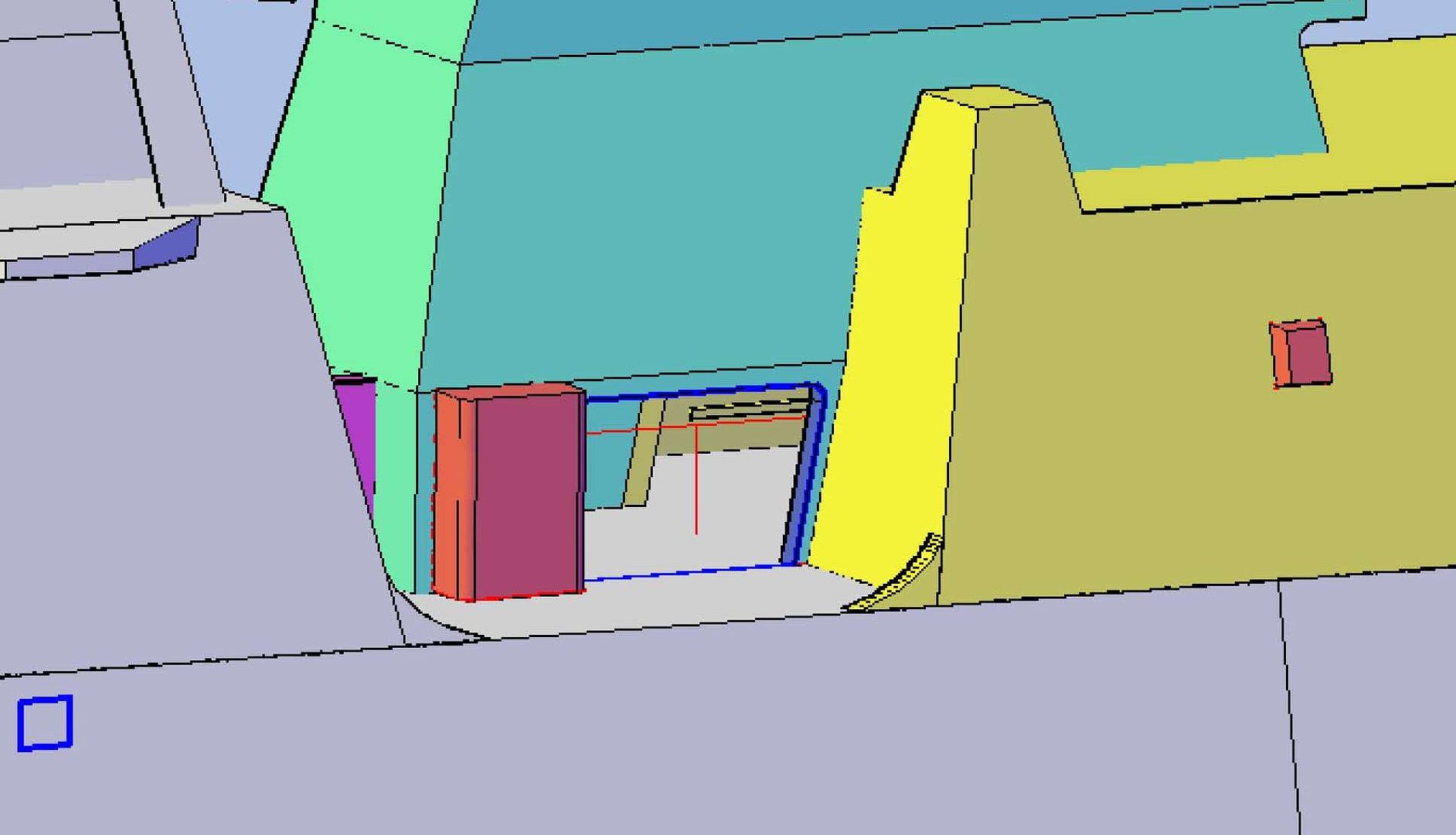 Next I did some steps that I later discovered were unnecessary, and had to undo, so I won’t describe them. After that, I used pictures to draw the vent on the forward side of the hangar. On all of the vents that I drew in this post, I used rectangles, then filleted the corners to 0.03”. 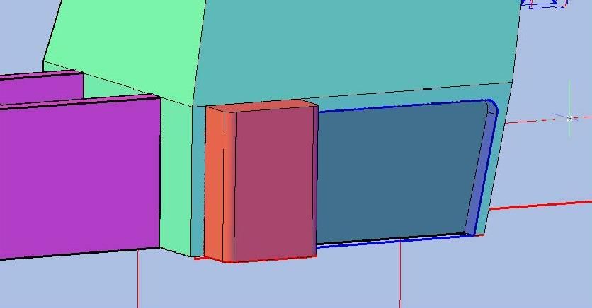 …And figuring that it was going to be PE, extruded it 0.020” into the surface and subtracted it. I then drew filleted rectangles for the side vents on the exhaust stack. 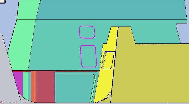 These vents are open and in pictures of both sides of the ship, you can see through, so I extruded these all the way through the stack… 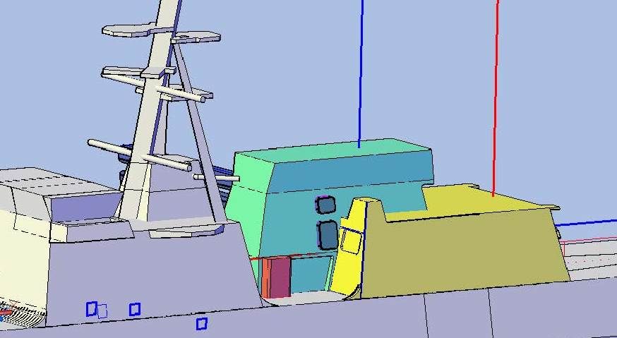 …And subtracted them.  Next was the smaller vent forward. Again, I drew it with a rectangle from pictures, but due to its smaller size filleted it at 0.02” instead of 0.03” like the previous ones.  This part again, will probably be PE, so I extruded it in 0.020”.  As long as I was in the area, I thought I would add the 10” Double Bitts that are on the deck. I started by drawing a square through the centerlines of them from the plans... 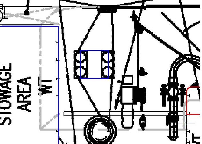 …And copying it to the model. 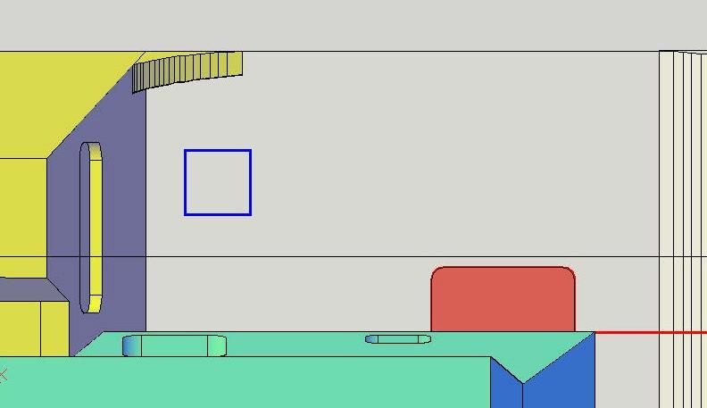 I then opened the 10” Double Bitt drawing file, oriented the coordinate systems properly and copied two of them onto the square. 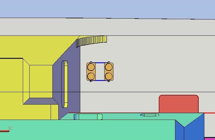 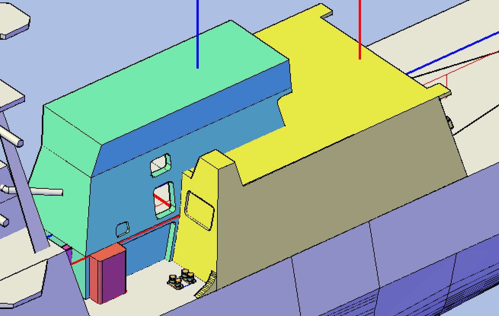 That was it for the session, but if you look at the last image you can see a couple of issues. First, you can see clear through to the deck in the vent holes, but if the Aviation Workshop and CIWS Control Station parts were present, you wouldn’t be able to. I thought that the part layers were turned off, but they weren’t. I turned all the layers on and they are gone. I guess I could have accidently deleted them at some point, but I’m blaming the ACAD gremlins. Also, my bone headed move was blocking the recess at the back side of the part. I will be doing corrections next. CHEERS!!!
[u][b]UPDATE 48[/b][/u]
Hi Everybody! :wave_1:
On Bertholf, the next thing I did was add the FAS Locker, first tracing the outline of it from the plans with a polyline…
[url=http://s1352.photobucket.com/user/rdutnell/media/USCG%20Cutter%20%20-%20Bertholf/USCGCutter-48-pix_Page_01_zps84433dce.jpg.html][img]http://i1352.photobucket.com/albums/q659/rdutnell/USCG%20Cutter%20%20-%20Bertholf/USCGCutter-48-pix_Page_01_zps84433dce.jpg[/img][/url]
…And copying the polyline to the model.
[url=http://s1352.photobucket.com/user/rdutnell/media/USCG%20Cutter%20%20-%20Bertholf/USCGCutter-48-pix_Page_02_zps2cffa966.jpg.html][img]http://i1352.photobucket.com/albums/q659/rdutnell/USCG%20Cutter%20%20-%20Bertholf/USCGCutter-48-pix_Page_02_zps2cffa966.jpg[/img][/url]
I then extruded the polyline up along the face of the exhaust stack part to the proper elevation.
[url=http://s1352.photobucket.com/user/rdutnell/media/USCG%20Cutter%20%20-%20Bertholf/USCGCutter-48-pix_Page_03_zpsb5d62e00.jpg.html][img]http://i1352.photobucket.com/albums/q659/rdutnell/USCG%20Cutter%20%20-%20Bertholf/USCGCutter-48-pix_Page_03_zpsb5d62e00.jpg[/img][/url]
Next I referred to pictures to draw the cutout in the exhaust stack, extruding the polyline created through the part…
[url=http://s1352.photobucket.com/user/rdutnell/media/USCG%20Cutter%20%20-%20Bertholf/USCGCutter-48-pix_Page_04_zps8a5bb58f.jpg.html][img]http://i1352.photobucket.com/albums/q659/rdutnell/USCG%20Cutter%20%20-%20Bertholf/USCGCutter-48-pix_Page_04_zps8a5bb58f.jpg[/img][/url]
…And subtracting it.
[url=http://s1352.photobucket.com/user/rdutnell/media/USCG%20Cutter%20%20-%20Bertholf/USCGCutter-48-pix_Page_05_zps226b0888.jpg.html][img]http://i1352.photobucket.com/albums/q659/rdutnell/USCG%20Cutter%20%20-%20Bertholf/USCGCutter-48-pix_Page_05_zps226b0888.jpg[/img][/url]
Next I did some steps that I later discovered were unnecessary, and had to undo, so I won’t describe them. After that, I used pictures to draw the vent on the forward side of the hangar. On all of the vents that I drew in this post, I used rectangles, then filleted the corners to 0.03”.
[url=http://s1352.photobucket.com/user/rdutnell/media/USCG%20Cutter%20%20-%20Bertholf/USCGCutter-48-pix_Page_06_zps5d7a361e.jpg.html][img]http://i1352.photobucket.com/albums/q659/rdutnell/USCG%20Cutter%20%20-%20Bertholf/USCGCutter-48-pix_Page_06_zps5d7a361e.jpg[/img][/url]
…And figuring that it was going to be PE, extruded it 0.020” into the surface and subtracted it. I then drew filleted rectangles for the side vents on the exhaust stack.
[url=http://s1352.photobucket.com/user/rdutnell/media/USCG%20Cutter%20%20-%20Bertholf/USCGCutter-48-pix_Page_09_zps00dc615b.jpg.html][img]http://i1352.photobucket.com/albums/q659/rdutnell/USCG%20Cutter%20%20-%20Bertholf/USCGCutter-48-pix_Page_09_zps00dc615b.jpg[/img][/url]
These vents are open and in pictures of both sides of the ship, you can see through, so I extruded these all the way through the stack…
[url=http://s1352.photobucket.com/user/rdutnell/media/USCG%20Cutter%20%20-%20Bertholf/USCGCutter-48-pix_Page_10_zps8b272793.jpg.html][img]http://i1352.photobucket.com/albums/q659/rdutnell/USCG%20Cutter%20%20-%20Bertholf/USCGCutter-48-pix_Page_10_zps8b272793.jpg[/img][/url]
…And subtracted them.
[url=http://s1352.photobucket.com/user/rdutnell/media/USCG%20Cutter%20%20-%20Bertholf/USCGCutter-48-pix_Page_11_zpsecfe1e53.jpg.html][img]http://i1352.photobucket.com/albums/q659/rdutnell/USCG%20Cutter%20%20-%20Bertholf/USCGCutter-48-pix_Page_11_zpsecfe1e53.jpg[/img][/url]
Next was the smaller vent forward. Again, I drew it with a rectangle from pictures, but due to its smaller size filleted it at 0.02” instead of 0.03” like the previous ones.
[url=http://s1352.photobucket.com/user/rdutnell/media/USCG%20Cutter%20%20-%20Bertholf/USCGCutter-48-pix_Page_12_zps25914cbf.jpg.html][img]http://i1352.photobucket.com/albums/q659/rdutnell/USCG%20Cutter%20%20-%20Bertholf/USCGCutter-48-pix_Page_12_zps25914cbf.jpg[/img][/url]
This part again, will probably be PE, so I extruded it in 0.020”.
[url=http://s1352.photobucket.com/user/rdutnell/media/USCG%20Cutter%20%20-%20Bertholf/USCGCutter-48-pix_Page_13_zps03357144.jpg.html][img]http://i1352.photobucket.com/albums/q659/rdutnell/USCG%20Cutter%20%20-%20Bertholf/USCGCutter-48-pix_Page_13_zps03357144.jpg[/img][/url]
As long as I was in the area, I thought I would add the 10” Double Bitts that are on the deck.
I started by drawing a square through the centerlines of them from the plans...
[url=http://s1352.photobucket.com/user/rdutnell/media/USCG%20Cutter%20%20-%20Bertholf/USCGCutter-48-pix_Page_14_zps63457418.jpg.html][img]http://i1352.photobucket.com/albums/q659/rdutnell/USCG%20Cutter%20%20-%20Bertholf/USCGCutter-48-pix_Page_14_zps63457418.jpg[/img][/url]
…And copying it to the model.
[url=http://s1352.photobucket.com/user/rdutnell/media/USCG%20Cutter%20%20-%20Bertholf/USCGCutter-48-pix_Page_15_zps67a8a543.jpg.html][img]http://i1352.photobucket.com/albums/q659/rdutnell/USCG%20Cutter%20%20-%20Bertholf/USCGCutter-48-pix_Page_15_zps67a8a543.jpg[/img][/url]
I then opened the 10” Double Bitt drawing file, oriented the coordinate systems properly and copied two of them onto the square.
[url=http://s1352.photobucket.com/user/rdutnell/media/USCG%20Cutter%20%20-%20Bertholf/USCGCutter-48-pix_Page_16_zps938bcb0c.jpg.html][img]http://i1352.photobucket.com/albums/q659/rdutnell/USCG%20Cutter%20%20-%20Bertholf/USCGCutter-48-pix_Page_16_zps938bcb0c.jpg[/img][/url]
[url=http://s1352.photobucket.com/user/rdutnell/media/USCG%20Cutter%20%20-%20Bertholf/USCGCutter-48-pix_Page_17_zps6660d7f2.jpg.html][img]http://i1352.photobucket.com/albums/q659/rdutnell/USCG%20Cutter%20%20-%20Bertholf/USCGCutter-48-pix_Page_17_zps6660d7f2.jpg[/img][/url]
That was it for the session, but if you look at the last image you can see a couple of issues. First, you can see clear through to the deck in the vent holes, but if the Aviation Workshop and CIWS Control Station parts were present, you wouldn’t be able to. I thought that the part layers were turned off, but they weren’t. I turned all the layers on and they are gone. I guess I could have accidently deleted them at some point, but I’m blaming the ACAD gremlins. Also, my bone headed move was blocking the recess at the back side of the part. I will be doing corrections next.
CHEERS!!!
|
|
|
|
Posted: Fri Jul 19, 2013 2:51 pm |
|
|
|
|
|
| |
Post subject: |
Re: USCGC Bertholf (WMSL-750) – A CAD Design for 3D Printing |
|
|
UPDATE 47 Hello Again Guys! The fun continues. As I was looking at the only hangar interior picture I have, debating on whether or not to do any more interior detailing until I talk to Pavel about it, I noticed duct work going to the bulkhead, and it occurred to me that it must correspond to one of the vents seen on the outside of the ship. So, I decided to add the vents, which would give me the positioning for the interior duct work if we later decide to add that feature. 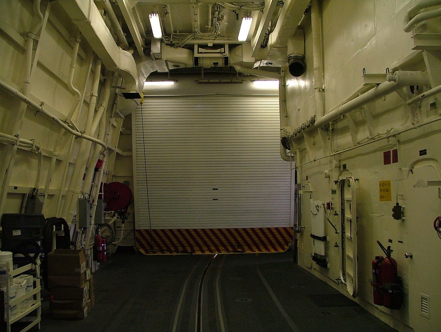 Surprisingly, the vents, though fairly prominent visual features of the ship, are not shown anywhere on the plan sheets I have. I therefore had to resort to using photographs and fortunately found two fairly straight on shots of the ship sides. I cropped the images slightly, imported them into AutoCad and scaled them. I then traced the outlines of the vents with rectangles. I did the port side first (The blueline is the line I used to scale the picture). As long as I was doing one vent I decided to do them all including the smaller ones that are flush with the surface (which are shown in red). 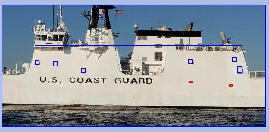 …Followed by the starboard side. 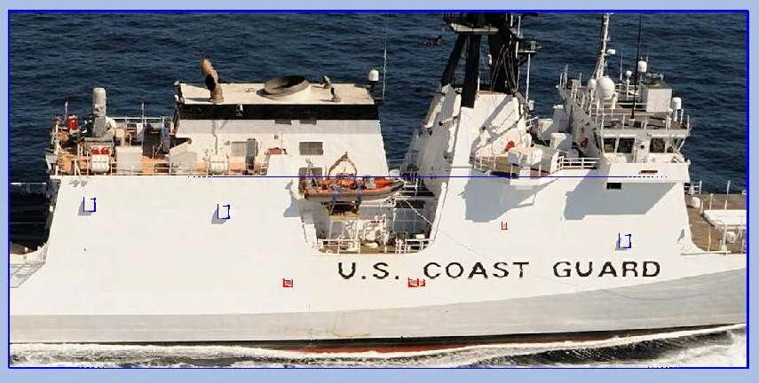 On the starboard side, I selected the 2 vents on the hangar…  …And used the PROJECTGEOMETRY command to project the shapes onto the hangar. 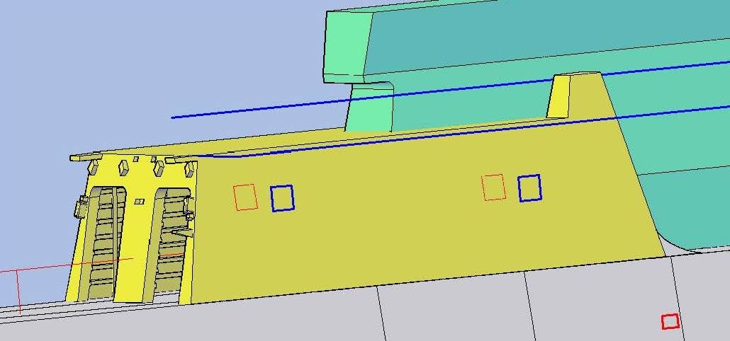 Note the vent hangar on the inside seems to be in the same position seen on the picture of the hangar interior. 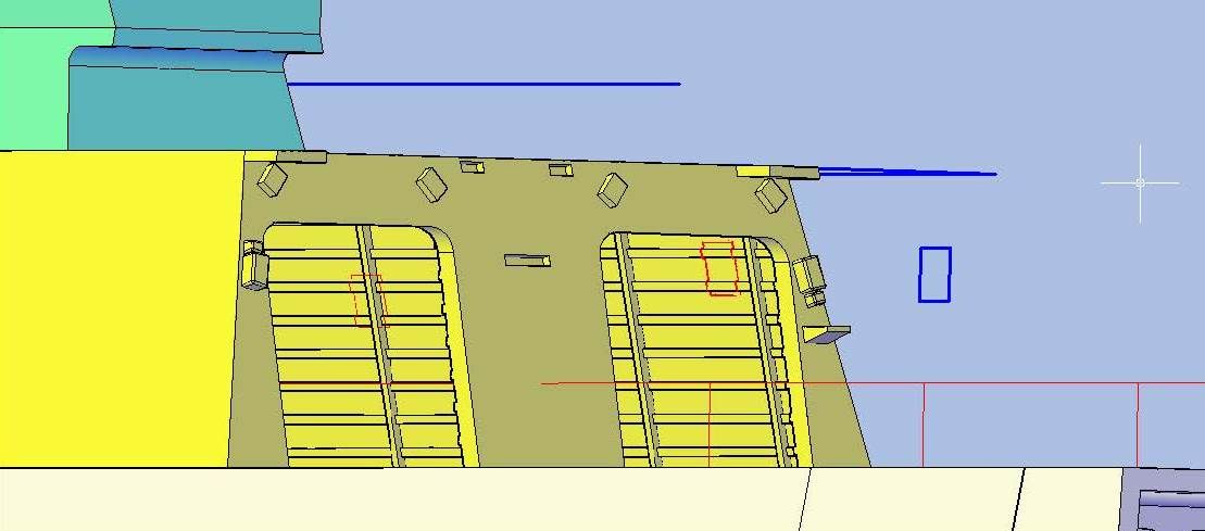 I then connected the corners of the projected lines and moved and rotated the coordinate system. 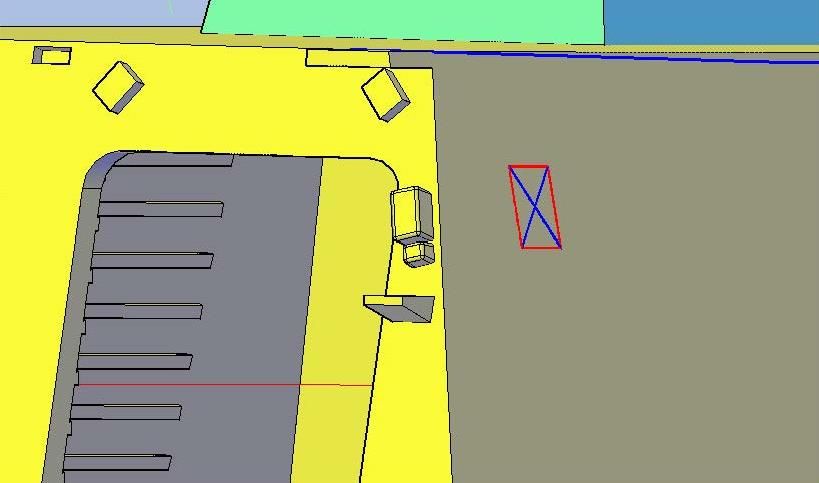 At this point, I started a new drawing and copied the rectangle and two cross lines to it. I named the file BulkheadVent1. 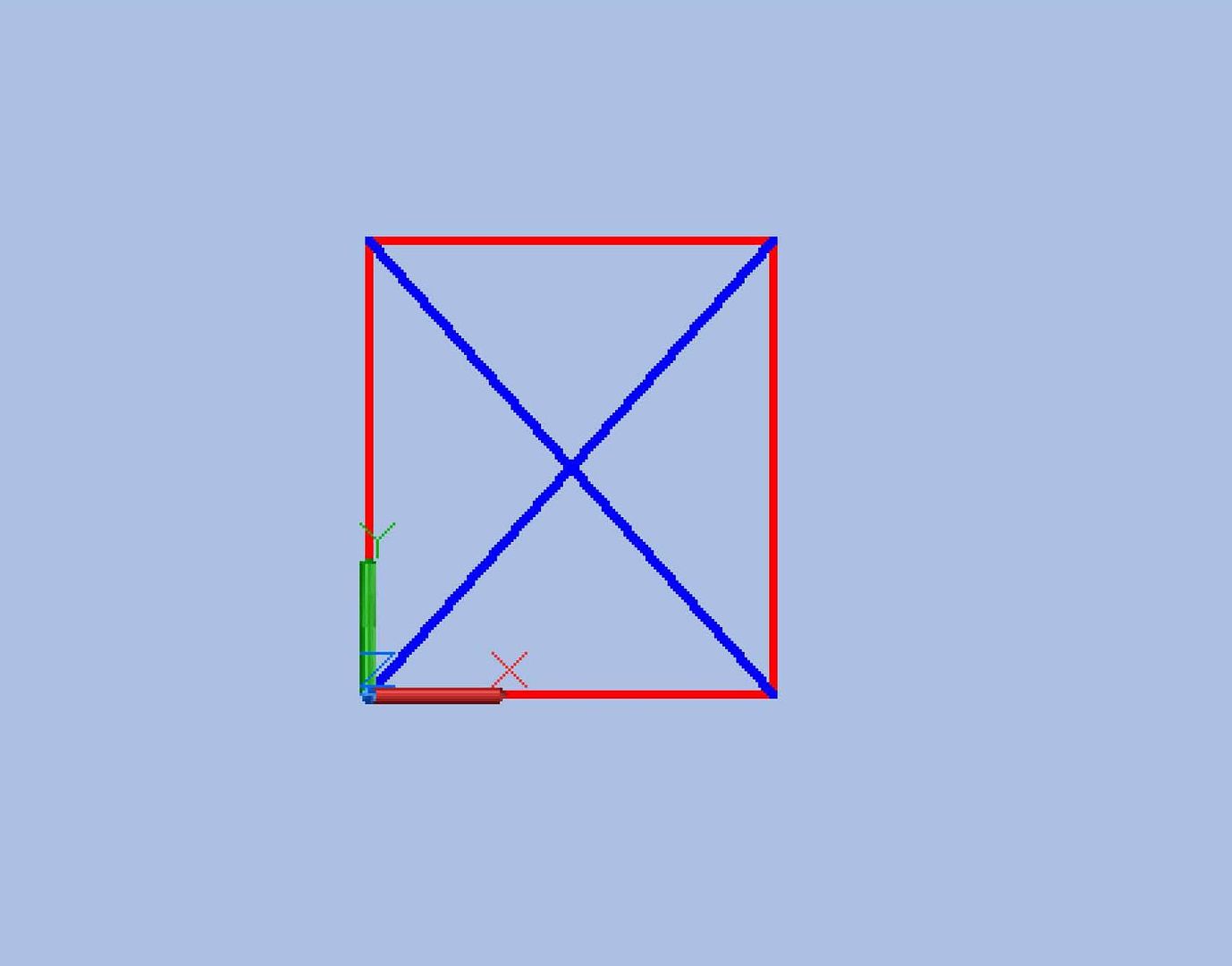 Next, I copied the rectangle up a short distance and moved the sides in and the top down… 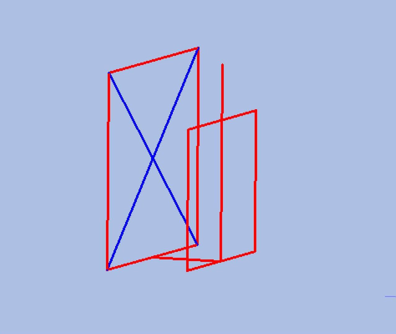 …And lofted them. I had to repeat this a few times until I thought it matched the pictures. The base is 0.105” x 0.093”, the top (or outboard side) is 0.092” x 0.076”, and it is 0.042” thick. 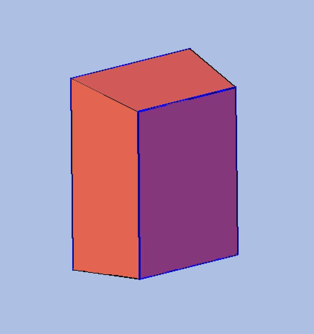 I then copied the newly created vent to the aft location on the hangar… 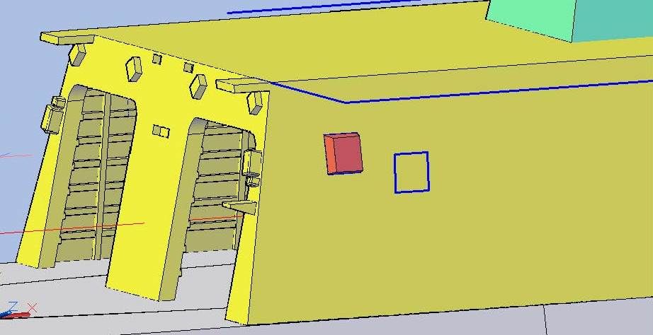 …And to the forward location. 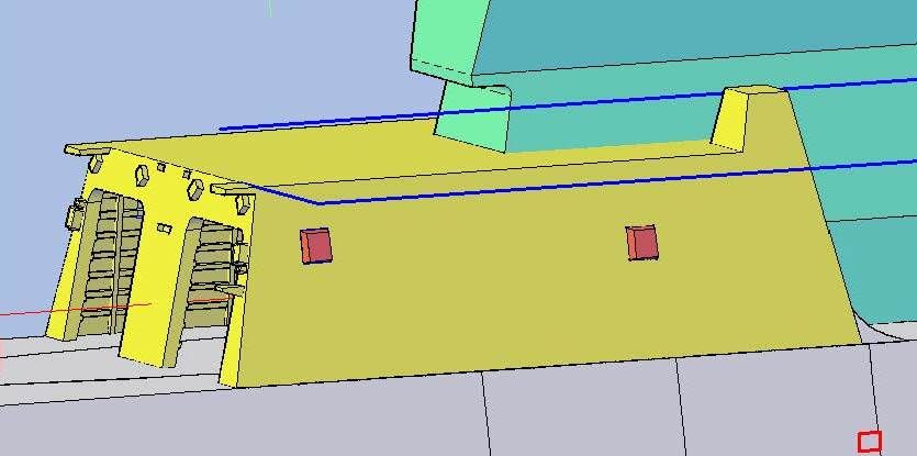 Next, I did the port side, which has an extra larger vent, located as shown below. 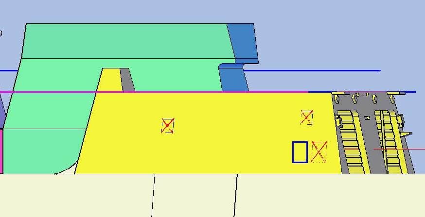 I repeated the same steps as before, naming the file BulkheadVent2. 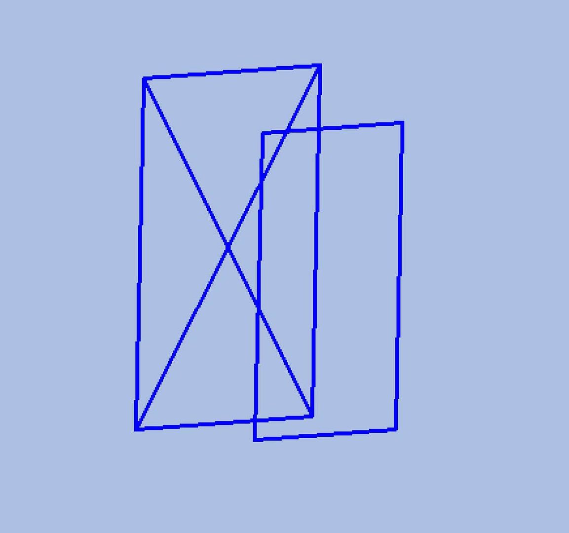 The base of the larger vent is 0.158” x 0.114”, the top (or outboard side) is 0.138” x 0.091”, and it is 0.064” thick.  The last step was to copy it to the hangar bulkhead, along with the smaller ones.  For the present, I have not joined the parts to the hangar, pending discussion with Pavel about it. He may want to keep them separate, but I kind of doubt it since they are so small. CHEERS!!! UPDATE 47
Hello Again Guys!
The fun continues. As I was looking at the only hangar interior picture I have, debating on whether or not to do any more interior detailing until I talk to Pavel about it, I noticed duct work going to the bulkhead, and it occurred to me that it must correspond to one of the vents seen on the outside of the ship. So, I decided to add the vents, which would give me the positioning for the interior duct work if we later decide to add that feature.
[url=http://s1352.photobucket.com/user/rdutnell/media/USCG%20Cutter%20%20-%20Bertholf/HangarInterior1_zps545aaaef.jpg.html][img]http://i1352.photobucket.com/albums/q659/rdutnell/USCG%20Cutter%20%20-%20Bertholf/HangarInterior1_zps545aaaef.jpg[/img][/url]
Surprisingly, the vents, though fairly prominent visual features of the ship, are not shown anywhere on the plan sheets I have. I therefore had to resort to using photographs and fortunately found two fairly straight on shots of the ship sides. I cropped the images slightly, imported them into AutoCad and scaled them. I then traced the outlines of the vents with rectangles.
I did the port side first (The blueline is the line I used to scale the picture). As long as I was doing one vent I decided to do them all including the smaller ones that are flush with the surface (which are shown in red).
[url=http://s1352.photobucket.com/user/rdutnell/media/USCG%20Cutter%20%20-%20Bertholf/USCGCutter-47-pix_Page_01_zps44d77ab4.jpg.html][img]http://i1352.photobucket.com/albums/q659/rdutnell/USCG%20Cutter%20%20-%20Bertholf/USCGCutter-47-pix_Page_01_zps44d77ab4.jpg[/img][/url]
…Followed by the starboard side.
[url=http://s1352.photobucket.com/user/rdutnell/media/USCG%20Cutter%20%20-%20Bertholf/USCGCutter-47-pix_Page_02_zps964a07ba.jpg.html][img]http://i1352.photobucket.com/albums/q659/rdutnell/USCG%20Cutter%20%20-%20Bertholf/USCGCutter-47-pix_Page_02_zps964a07ba.jpg[/img][/url]
On the starboard side, I selected the 2 vents on the hangar…
[url=http://s1352.photobucket.com/user/rdutnell/media/USCG%20Cutter%20%20-%20Bertholf/USCGCutter-47-pix_Page_03_zpsae1c0bee.jpg.html][img]http://i1352.photobucket.com/albums/q659/rdutnell/USCG%20Cutter%20%20-%20Bertholf/USCGCutter-47-pix_Page_03_zpsae1c0bee.jpg[/img][/url]
…And used the PROJECTGEOMETRY command to project the shapes onto the hangar.
[url=http://s1352.photobucket.com/user/rdutnell/media/USCG%20Cutter%20%20-%20Bertholf/USCGCutter-47-pix_Page_04_zps155ef8af.jpg.html][img]http://i1352.photobucket.com/albums/q659/rdutnell/USCG%20Cutter%20%20-%20Bertholf/USCGCutter-47-pix_Page_04_zps155ef8af.jpg[/img][/url]
Note the vent hangar on the inside seems to be in the same position seen on the picture of the hangar interior.
[url=http://s1352.photobucket.com/user/rdutnell/media/USCG%20Cutter%20%20-%20Bertholf/USCGCutter-47-pix_Page_05_zpscc9f6087.jpg.html][img]http://i1352.photobucket.com/albums/q659/rdutnell/USCG%20Cutter%20%20-%20Bertholf/USCGCutter-47-pix_Page_05_zpscc9f6087.jpg[/img][/url]
I then connected the corners of the projected lines and moved and rotated the coordinate system.
[url=http://s1352.photobucket.com/user/rdutnell/media/USCG%20Cutter%20%20-%20Bertholf/USCGCutter-47-pix_Page_06_zps13fd5053.jpg.html][img]http://i1352.photobucket.com/albums/q659/rdutnell/USCG%20Cutter%20%20-%20Bertholf/USCGCutter-47-pix_Page_06_zps13fd5053.jpg[/img][/url]
At this point, I started a new drawing and copied the rectangle and two cross lines to it. I named the file BulkheadVent1.
[url=http://s1352.photobucket.com/user/rdutnell/media/USCG%20Cutter%20%20-%20Bertholf/USCGCutter-47-pix_Page_07_zpsea6bbbcf.jpg.html][img]http://i1352.photobucket.com/albums/q659/rdutnell/USCG%20Cutter%20%20-%20Bertholf/USCGCutter-47-pix_Page_07_zpsea6bbbcf.jpg[/img][/url]
Next, I copied the rectangle up a short distance and moved the sides in and the top down…
[url=http://s1352.photobucket.com/user/rdutnell/media/USCG%20Cutter%20%20-%20Bertholf/USCGCutter-47-pix_Page_08_zpsdac89f67.jpg.html][img]http://i1352.photobucket.com/albums/q659/rdutnell/USCG%20Cutter%20%20-%20Bertholf/USCGCutter-47-pix_Page_08_zpsdac89f67.jpg[/img][/url]
…And lofted them. I had to repeat this a few times until I thought it matched the pictures. The base is 0.105” x 0.093”, the top (or outboard side) is 0.092” x 0.076”, and it is 0.042” thick.
[url=http://s1352.photobucket.com/user/rdutnell/media/USCG%20Cutter%20%20-%20Bertholf/USCGCutter-47-pix_Page_09_zps5d32f6e0.jpg.html][img]http://i1352.photobucket.com/albums/q659/rdutnell/USCG%20Cutter%20%20-%20Bertholf/USCGCutter-47-pix_Page_09_zps5d32f6e0.jpg[/img][/url]
I then copied the newly created vent to the aft location on the hangar…
[url=http://s1352.photobucket.com/user/rdutnell/media/USCG%20Cutter%20%20-%20Bertholf/USCGCutter-47-pix_Page_10_zpsc14f5346.jpg.html][img]http://i1352.photobucket.com/albums/q659/rdutnell/USCG%20Cutter%20%20-%20Bertholf/USCGCutter-47-pix_Page_10_zpsc14f5346.jpg[/img][/url]
…And to the forward location.
[url=http://s1352.photobucket.com/user/rdutnell/media/USCG%20Cutter%20%20-%20Bertholf/USCGCutter-47-pix_Page_11_zpsc571d2f2.jpg.html][img]http://i1352.photobucket.com/albums/q659/rdutnell/USCG%20Cutter%20%20-%20Bertholf/USCGCutter-47-pix_Page_11_zpsc571d2f2.jpg[/img][/url]
Next, I did the port side, which has an extra larger vent, located as shown below.
[url=http://s1352.photobucket.com/user/rdutnell/media/USCG%20Cutter%20%20-%20Bertholf/USCGCutter-47-pix_Page_12_zps18d2f8e9.jpg.html][img]http://i1352.photobucket.com/albums/q659/rdutnell/USCG%20Cutter%20%20-%20Bertholf/USCGCutter-47-pix_Page_12_zps18d2f8e9.jpg[/img][/url]
I repeated the same steps as before, naming the file BulkheadVent2.
[url=http://s1352.photobucket.com/user/rdutnell/media/USCG%20Cutter%20%20-%20Bertholf/USCGCutter-47-pix_Page_13_zps016414ca.jpg.html][img]http://i1352.photobucket.com/albums/q659/rdutnell/USCG%20Cutter%20%20-%20Bertholf/USCGCutter-47-pix_Page_13_zps016414ca.jpg[/img][/url]
The base of the larger vent is 0.158” x 0.114”, the top (or outboard side) is 0.138” x 0.091”, and it is 0.064” thick.
[url=http://s1352.photobucket.com/user/rdutnell/media/USCG%20Cutter%20%20-%20Bertholf/USCGCutter-47-pix_Page_14_zps0cdb5d8d.jpg.html][img]http://i1352.photobucket.com/albums/q659/rdutnell/USCG%20Cutter%20%20-%20Bertholf/USCGCutter-47-pix_Page_14_zps0cdb5d8d.jpg[/img][/url]
The last step was to copy it to the hangar bulkhead, along with the smaller ones.
[url=http://s1352.photobucket.com/user/rdutnell/media/USCG%20Cutter%20%20-%20Bertholf/USCGCutter-47-pix_Page_15_zpsce6b712e.jpg.html][img]http://i1352.photobucket.com/albums/q659/rdutnell/USCG%20Cutter%20%20-%20Bertholf/USCGCutter-47-pix_Page_15_zpsce6b712e.jpg[/img][/url]
For the present, I have not joined the parts to the hangar, pending discussion with Pavel about it. He may want to keep them separate, but I kind of doubt it since they are so small.
CHEERS!!!
|
|
|
|
Posted: Thu Jul 18, 2013 5:02 pm |
|
|
|
|
|
| |
Post subject: |
Re: USCGC Bertholf (WMSL-750) – A CAD Design for 3D Printing |
|
|
UPDATE 46 Hi Guys! Tuesday night, after I put the detailing on the interior bulkhead walls of the hangar, I decided to make the fan rooms. To begin the process, I first traced their outlines from the plan sheet… 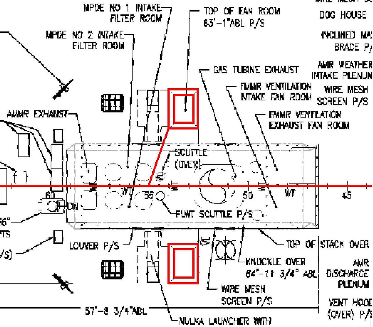 …And copied them to the model. 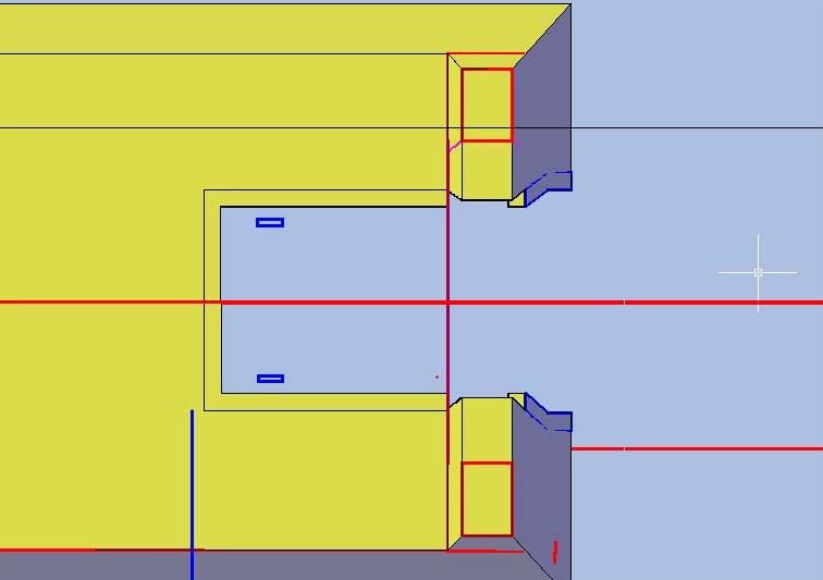 I then rest their elevations (or heights above the datum) based on the plans, and the alignment was spot on, so I created a polyline between the interior faces of the fan rooms, extruded it... 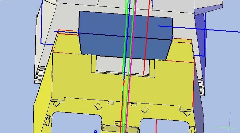 …And subtracted it from the hangar. 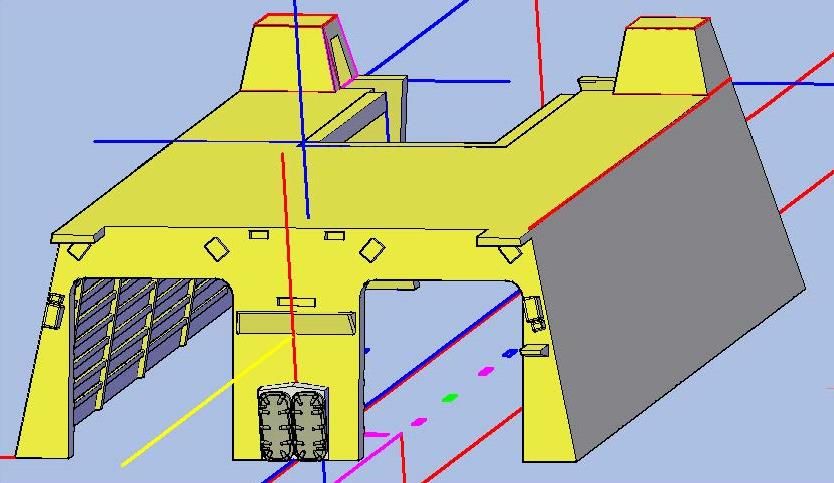 Because I had previously shelled the part, slicing it left gaps I had to fill. To fill the sloped vertical surface I traced the outline with a polyline, and moved the corners in a liitle bit. 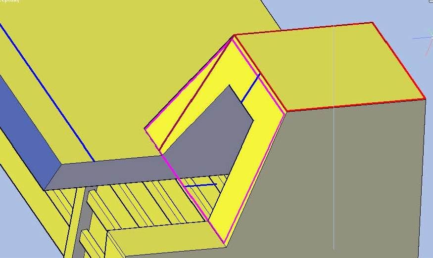 I then extruded this polyline 0.046” horizontally… 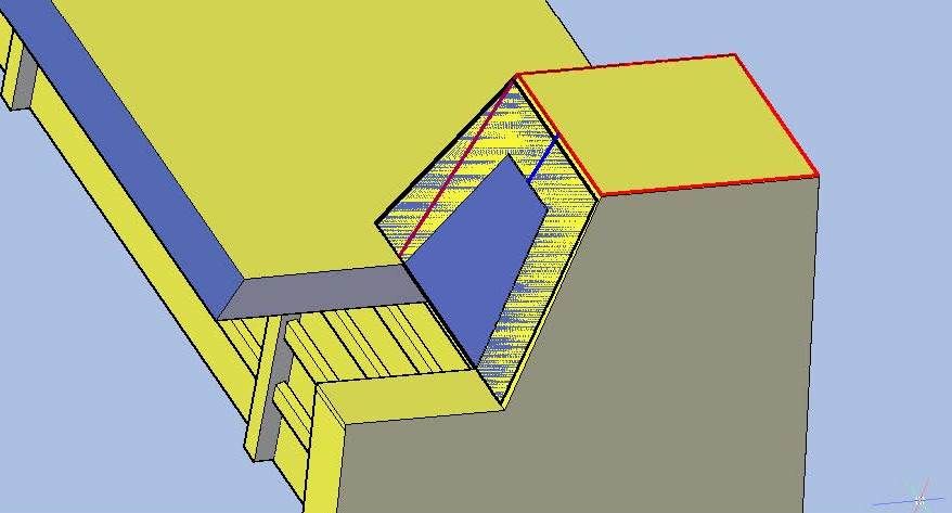 …And joined it to the hangar. 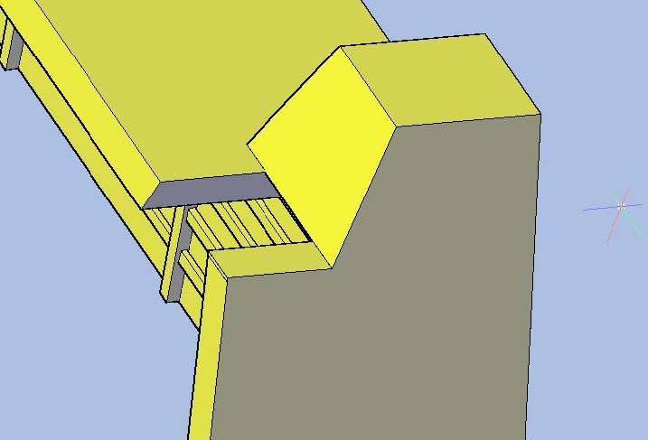 I then repeated the process for the other side. 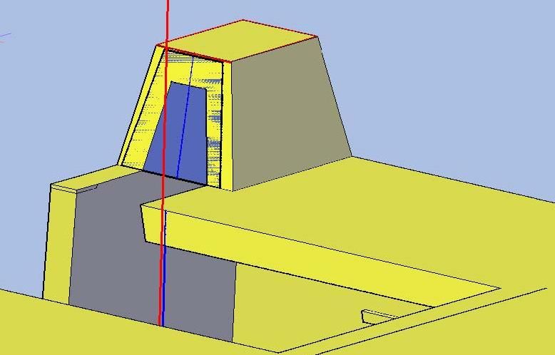 The horizontal fill was created by extruding a polyline 0.046” down the sloped surface seen in the foreground of the image below. 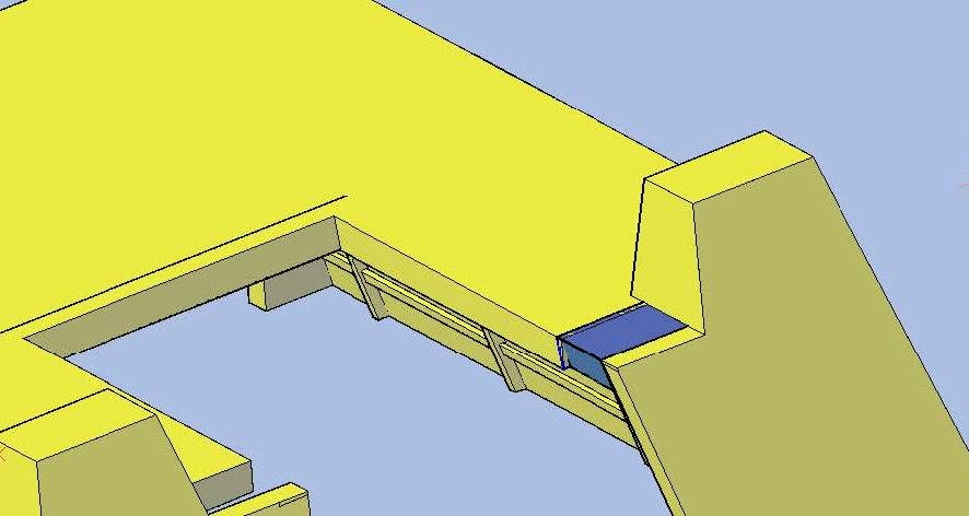 I repeated this for the other side, and as you can see in the image below, a notch was created due to the different slopes of the interior edges. It won’t matter though because it won’t be visible when the model is assembled. 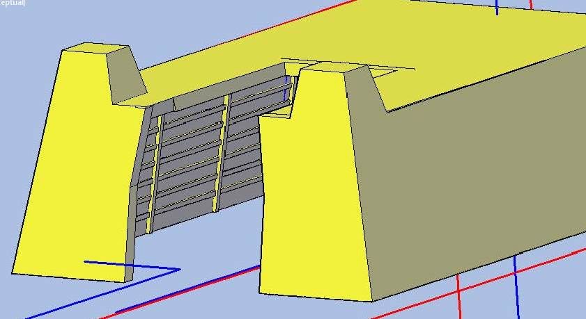 At this point, I redid the interior parts that I had blown earlier. Unfortunately I didn’t document it. But here is what I have. First is, what I am calling, the Aviation Workshop. The object extends well forward of the real workshop, but not knowing what else to call it I thought that that would suffice. 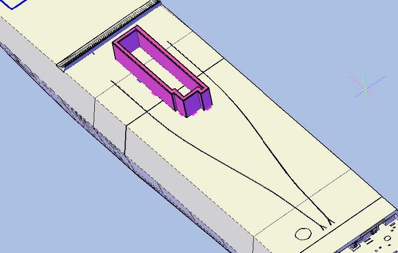 Next is the CIWS Control Station, named as such for the same reason as the Aviation Workshop, which goes on top of the Aviation Workshop part. 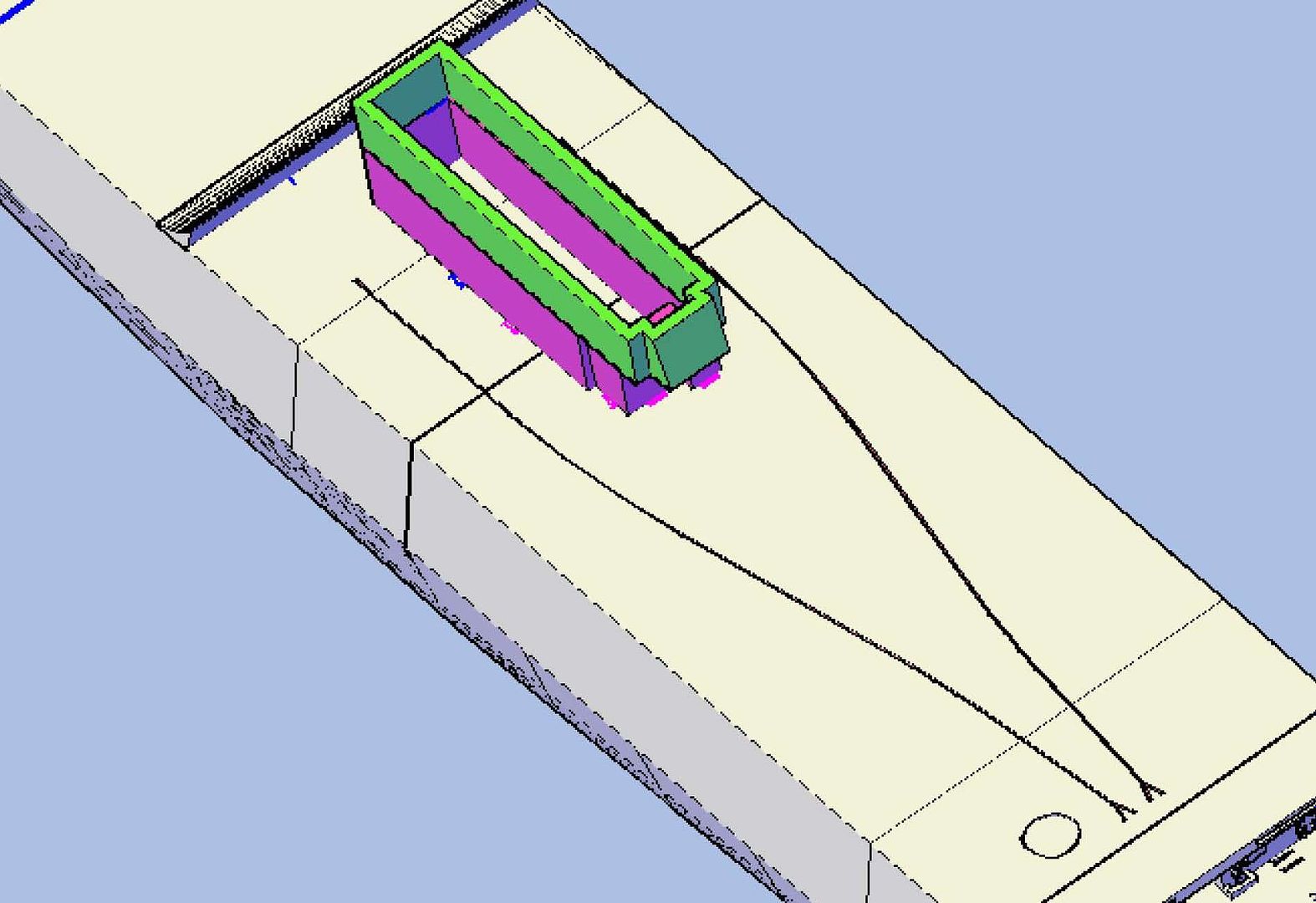 This is followed by the forward bulkheads and platforms on both the port and starboard sides… 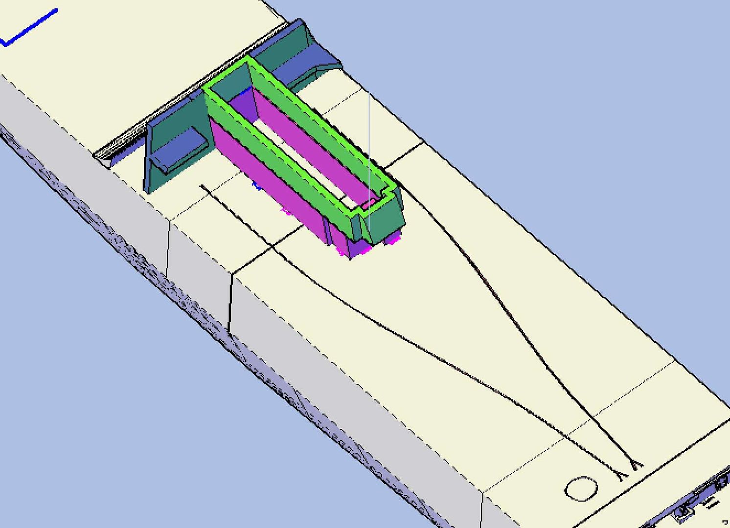 …Then the hangar… 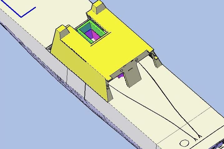 …And last but not least, what I am calling, the Exhaust Stack. 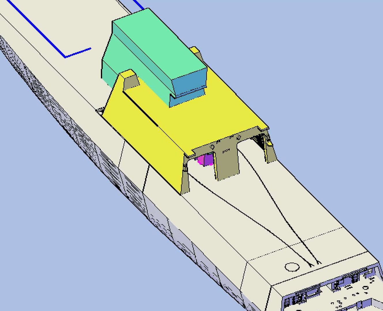 Each of these parts is likely to be split into multiple parts, but I haven’t discussed this with Pavel, so for the time being, that is all I am doing with the structure of these parts. I didn’t get anything done on Bertholf yesterday because I received the first test piece I designed to see just what the printer’s capabilities are. The results of this first test are posted at: viewtopic.php?f=2&t=148935CHEERS!!! UPDATE 46
Hi Guys!
Tuesday night, after I put the detailing on the interior bulkhead walls of the hangar, I decided to make the fan rooms. To begin the process, I first traced their outlines from the plan sheet…
[url=http://s1352.photobucket.com/user/rdutnell/media/USCG%20Cutter%20%20-%20Bertholf/USCGCutter-46-pix_Page_01_zps80ce9841.jpg.html][img]http://i1352.photobucket.com/albums/q659/rdutnell/USCG%20Cutter%20%20-%20Bertholf/USCGCutter-46-pix_Page_01_zps80ce9841.jpg[/img][/url]
…And copied them to the model.
[url=http://s1352.photobucket.com/user/rdutnell/media/USCG%20Cutter%20%20-%20Bertholf/USCGCutter-46-pix_Page_02_zpscb9e435c.jpg.html][img]http://i1352.photobucket.com/albums/q659/rdutnell/USCG%20Cutter%20%20-%20Bertholf/USCGCutter-46-pix_Page_02_zpscb9e435c.jpg[/img][/url]
I then rest their elevations (or heights above the datum) based on the plans, and the alignment was spot on, so I created a polyline between the interior faces of the fan rooms, extruded it...
[url=http://s1352.photobucket.com/user/rdutnell/media/USCG%20Cutter%20%20-%20Bertholf/USCGCutter-46-pix_Page_03_zps6df92f0a.jpg.html][img]http://i1352.photobucket.com/albums/q659/rdutnell/USCG%20Cutter%20%20-%20Bertholf/USCGCutter-46-pix_Page_03_zps6df92f0a.jpg[/img][/url]
…And subtracted it from the hangar.
[url=http://s1352.photobucket.com/user/rdutnell/media/USCG%20Cutter%20%20-%20Bertholf/USCGCutter-46-pix_Page_04_zps1105f982.jpg.html][img]http://i1352.photobucket.com/albums/q659/rdutnell/USCG%20Cutter%20%20-%20Bertholf/USCGCutter-46-pix_Page_04_zps1105f982.jpg[/img][/url]
Because I had previously shelled the part, slicing it left gaps I had to fill. To fill the sloped vertical surface I traced the outline with a polyline, and moved the corners in a liitle bit.
[url=http://s1352.photobucket.com/user/rdutnell/media/USCG%20Cutter%20%20-%20Bertholf/USCGCutter-46-pix_Page_05_zpse48af1cc.jpg.html][img]http://i1352.photobucket.com/albums/q659/rdutnell/USCG%20Cutter%20%20-%20Bertholf/USCGCutter-46-pix_Page_05_zpse48af1cc.jpg[/img][/url]
I then extruded this polyline 0.046” horizontally…
[url=http://s1352.photobucket.com/user/rdutnell/media/USCG%20Cutter%20%20-%20Bertholf/USCGCutter-46-pix_Page_06_zpsac70c9f7.jpg.html][img]http://i1352.photobucket.com/albums/q659/rdutnell/USCG%20Cutter%20%20-%20Bertholf/USCGCutter-46-pix_Page_06_zpsac70c9f7.jpg[/img][/url]
…And joined it to the hangar.
[url=http://s1352.photobucket.com/user/rdutnell/media/USCG%20Cutter%20%20-%20Bertholf/USCGCutter-46-pix_Page_07_zps0852c394.jpg.html][img]http://i1352.photobucket.com/albums/q659/rdutnell/USCG%20Cutter%20%20-%20Bertholf/USCGCutter-46-pix_Page_07_zps0852c394.jpg[/img][/url]
I then repeated the process for the other side.
[url=http://s1352.photobucket.com/user/rdutnell/media/USCG%20Cutter%20%20-%20Bertholf/USCGCutter-46-pix_Page_08_zpsf3f20102.jpg.html][img]http://i1352.photobucket.com/albums/q659/rdutnell/USCG%20Cutter%20%20-%20Bertholf/USCGCutter-46-pix_Page_08_zpsf3f20102.jpg[/img][/url]
The horizontal fill was created by extruding a polyline 0.046” down the sloped surface seen in the foreground of the image below.
[url=http://s1352.photobucket.com/user/rdutnell/media/USCG%20Cutter%20%20-%20Bertholf/USCGCutter-46-pix_Page_09_zps1f0855aa.jpg.html][img]http://i1352.photobucket.com/albums/q659/rdutnell/USCG%20Cutter%20%20-%20Bertholf/USCGCutter-46-pix_Page_09_zps1f0855aa.jpg[/img][/url]
I repeated this for the other side, and as you can see in the image below, a notch was created due to the different slopes of the interior edges. It won’t matter though because it won’t be visible when the model is assembled.
[url=http://s1352.photobucket.com/user/rdutnell/media/USCG%20Cutter%20%20-%20Bertholf/USCGCutter-46-pix_Page_10_zps96286e64.jpg.html][img]http://i1352.photobucket.com/albums/q659/rdutnell/USCG%20Cutter%20%20-%20Bertholf/USCGCutter-46-pix_Page_10_zps96286e64.jpg[/img][/url]
At this point, I redid the interior parts that I had blown earlier. Unfortunately I didn’t document it. But here is what I have.
First is, what I am calling, the Aviation Workshop. The object extends well forward of the real workshop, but not knowing what else to call it I thought that that would suffice.
[url=http://s1352.photobucket.com/user/rdutnell/media/USCG%20Cutter%20%20-%20Bertholf/USCGCutter-46-pix_Page_11_zps359dc8ee.jpg.html][img]http://i1352.photobucket.com/albums/q659/rdutnell/USCG%20Cutter%20%20-%20Bertholf/USCGCutter-46-pix_Page_11_zps359dc8ee.jpg[/img][/url]
Next is the CIWS Control Station, named as such for the same reason as the Aviation Workshop, which goes on top of the Aviation Workshop part.
[url=http://s1352.photobucket.com/user/rdutnell/media/USCG%20Cutter%20%20-%20Bertholf/USCGCutter-46-pix_Page_12_zpsd1255e8f.jpg.html][img]http://i1352.photobucket.com/albums/q659/rdutnell/USCG%20Cutter%20%20-%20Bertholf/USCGCutter-46-pix_Page_12_zpsd1255e8f.jpg[/img][/url]
This is followed by the forward bulkheads and platforms on both the port and starboard sides…
[url=http://s1352.photobucket.com/user/rdutnell/media/USCG%20Cutter%20%20-%20Bertholf/USCGCutter-46-pix_Page_13_zps4dfd13b6.jpg.html][img]http://i1352.photobucket.com/albums/q659/rdutnell/USCG%20Cutter%20%20-%20Bertholf/USCGCutter-46-pix_Page_13_zps4dfd13b6.jpg[/img][/url]
…Then the hangar…
[url=http://s1352.photobucket.com/user/rdutnell/media/USCG%20Cutter%20%20-%20Bertholf/USCGCutter-46-pix_Page_14_zps3aaddb9d.jpg.html][img]http://i1352.photobucket.com/albums/q659/rdutnell/USCG%20Cutter%20%20-%20Bertholf/USCGCutter-46-pix_Page_14_zps3aaddb9d.jpg[/img][/url]
…And last but not least, what I am calling, the Exhaust Stack.
[url=http://s1352.photobucket.com/user/rdutnell/media/USCG%20Cutter%20%20-%20Bertholf/USCGCutter-46-pix_Page_15_zps8607423a.jpg.html][img]http://i1352.photobucket.com/albums/q659/rdutnell/USCG%20Cutter%20%20-%20Bertholf/USCGCutter-46-pix_Page_15_zps8607423a.jpg[/img][/url]
Each of these parts is likely to be split into multiple parts, but I haven’t discussed this with Pavel, so for the time being, that is all I am doing with the structure of these parts.
I didn’t get anything done on Bertholf yesterday because I received the first test piece I designed to see just what the printer’s capabilities are. The results of this first test are posted at:
http://www.shipmodels.info/mws_forum/viewtopic.php?f=2&t=148935
CHEERS!!!
|
|
|
|
Posted: Thu Jul 18, 2013 11:37 am |
|
|
|
|
|
| |
Post subject: |
Re: USCGC Bertholf (WMSL-750) – A CAD Design for 3D Printing |
|
|
UPDATE 45It didn’t take me long to realize that I had blown some of what I did in the last post and flat didn’t like other parts, but I decided to put the supports seen on the interior bulkheads of the hangar. I did the horizontal beams first, starting with a 0.017” x 0.075” rectangle… 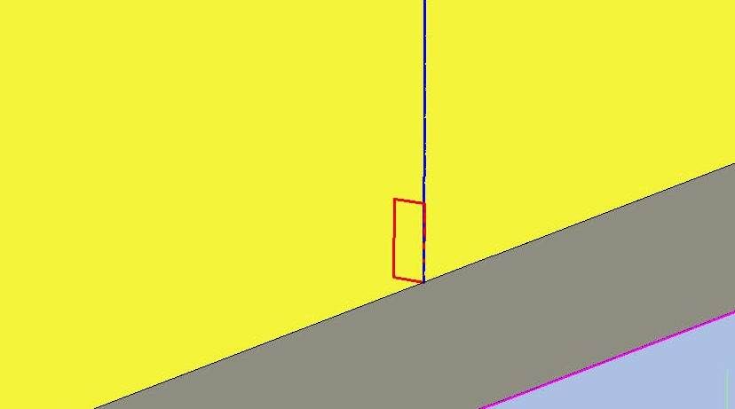 …Which I copied up the bulkhead. 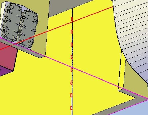 I then moved them to the forward corner and extruded them. 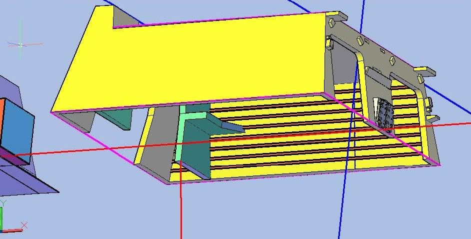 Next I mirrored them to the other side. 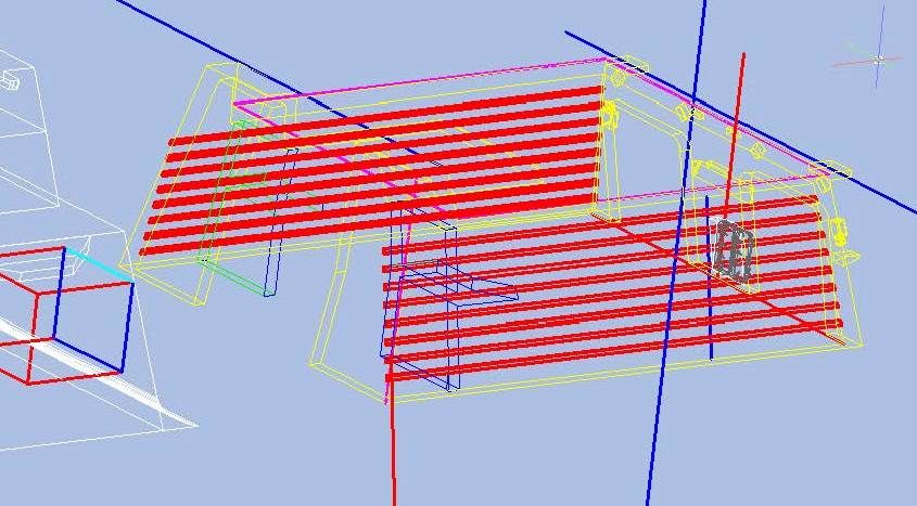 I sliced them off at the forward bulkheads, because they wouldn’t be visible so why waste the extra material? 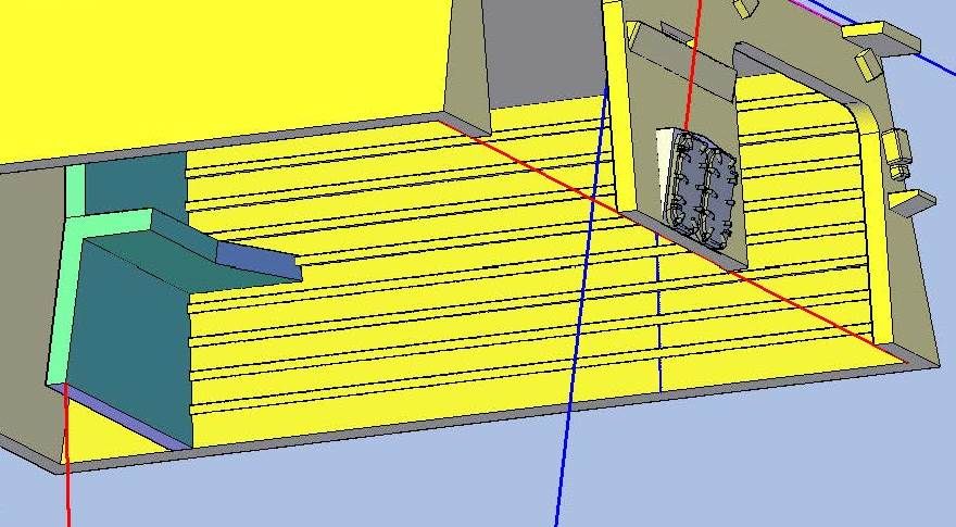 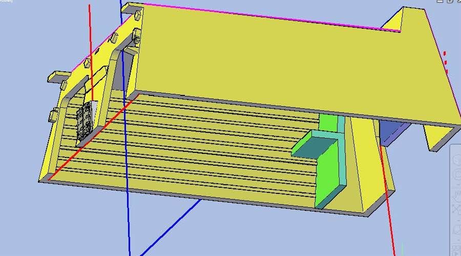 I then made the beams on the inside of the aft bulkhead, by copying the rectangle I started with, rotating it, extruding it and copying it multiple times. 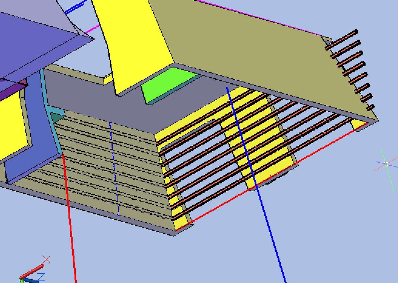 . Dicing and slicing was next. 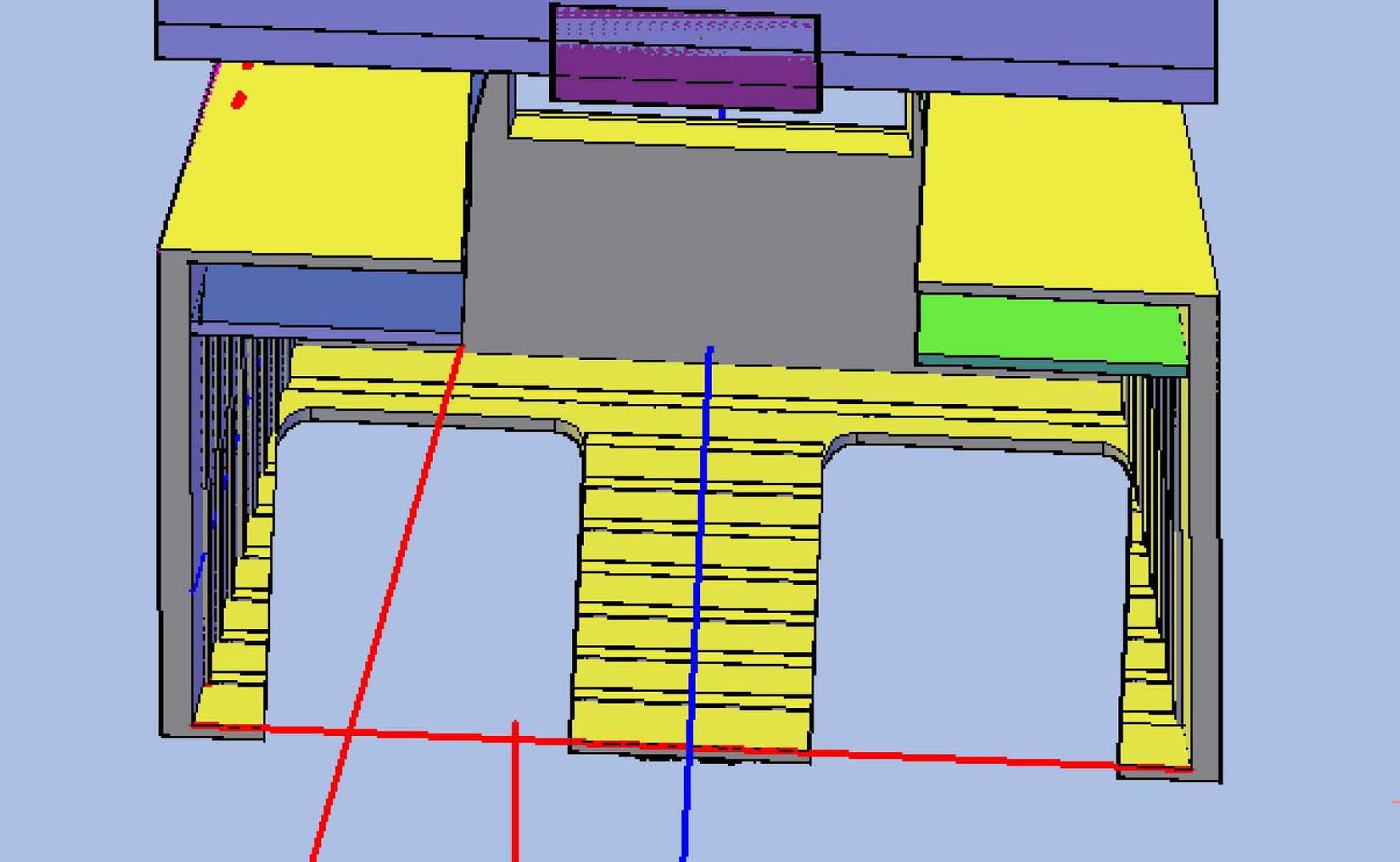 The vertical beams were made using a 0.017” square in a manner similar to the horizontal beams but instead of 8 rows, there were only 4 columns. 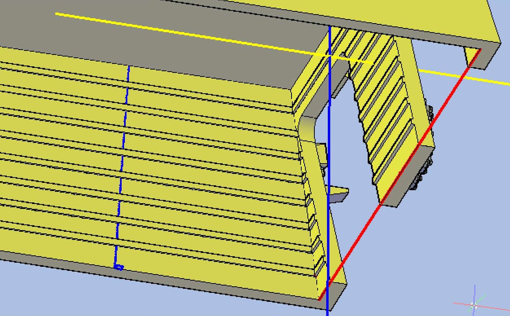 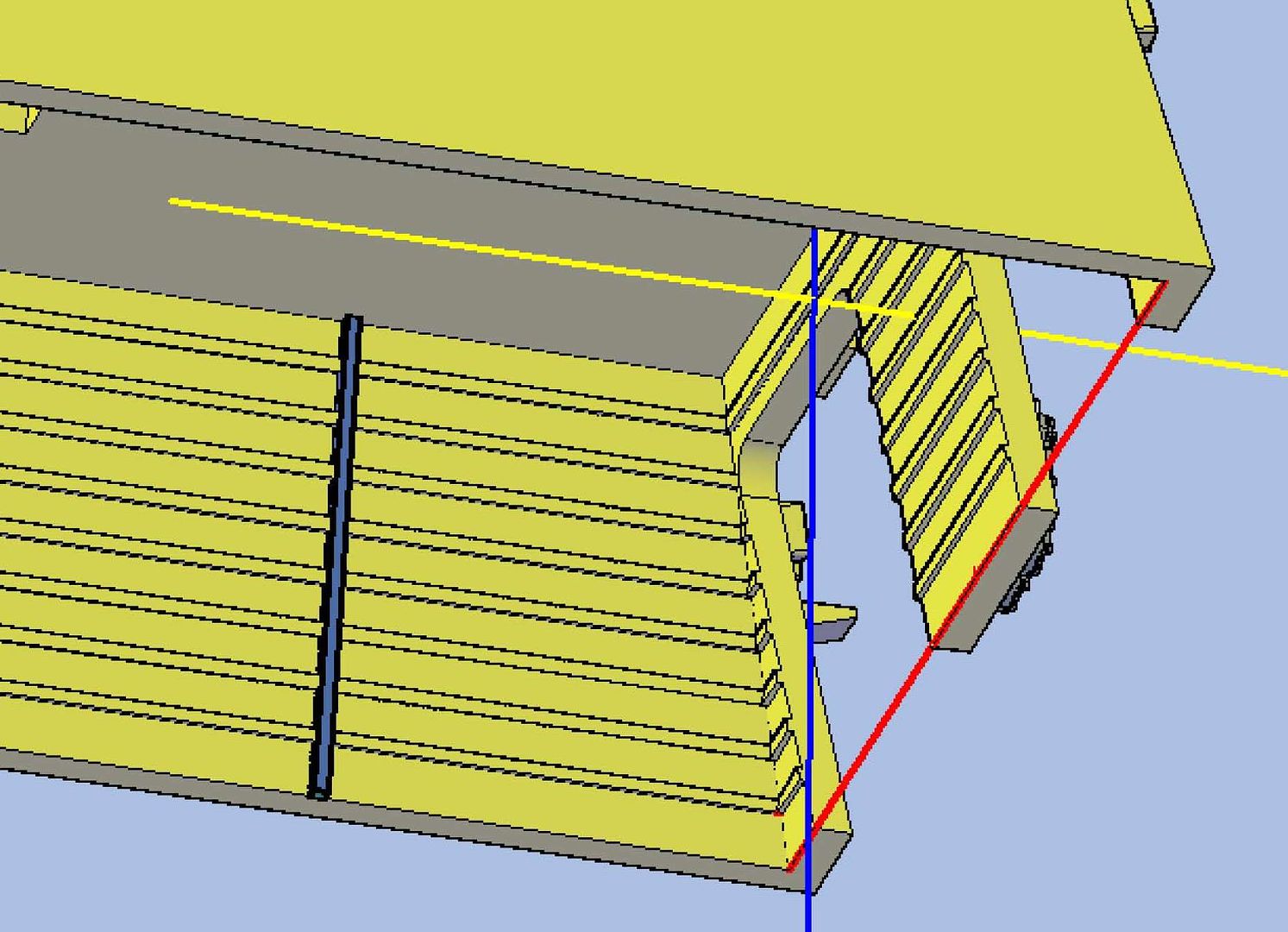 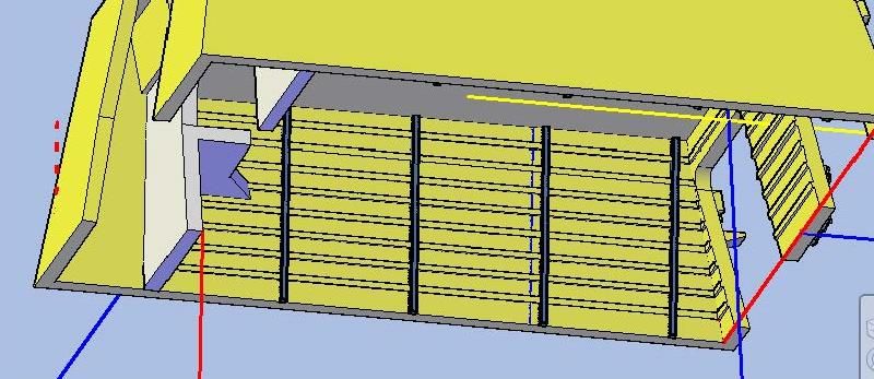 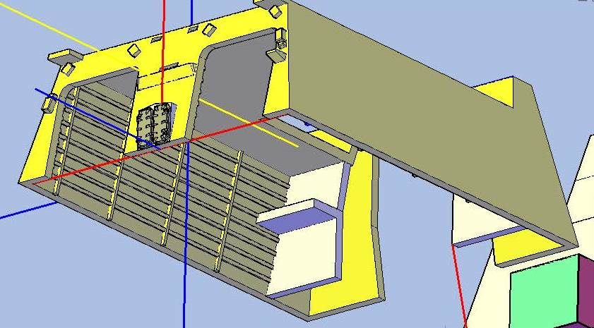 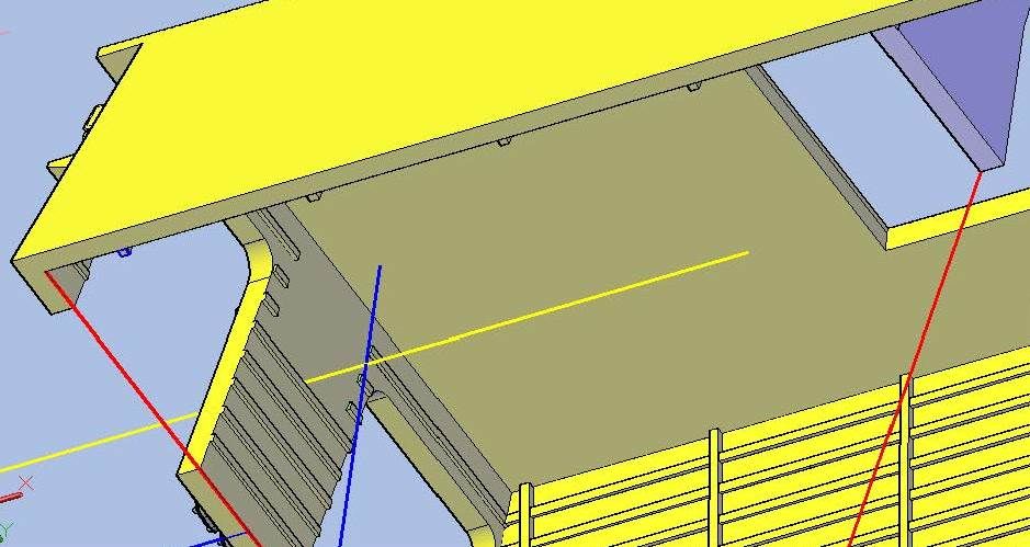 Now back to fix the stuff I blew. CHEERS!!!
[u][b]UPDATE 45[/b][/u]
It didn’t take me long to realize that I had blown some of what I did in the last post and flat didn’t like other parts, but I decided to put the supports seen on the interior bulkheads of the hangar. I did the horizontal beams first, starting with a 0.017” x 0.075” rectangle…
[url=http://s1352.photobucket.com/user/rdutnell/media/USCG%20Cutter%20%20-%20Bertholf/USCGCutter-45-pix_Page_01_zps11918d95.jpg.html][img]http://i1352.photobucket.com/albums/q659/rdutnell/USCG%20Cutter%20%20-%20Bertholf/USCGCutter-45-pix_Page_01_zps11918d95.jpg[/img][/url]
…Which I copied up the bulkhead.
[url=http://s1352.photobucket.com/user/rdutnell/media/USCG%20Cutter%20%20-%20Bertholf/USCGCutter-45-pix_Page_02_zps62398244.jpg.html][img]http://i1352.photobucket.com/albums/q659/rdutnell/USCG%20Cutter%20%20-%20Bertholf/USCGCutter-45-pix_Page_02_zps62398244.jpg[/img][/url]
I then moved them to the forward corner and extruded them.
[url=http://s1352.photobucket.com/user/rdutnell/media/USCG%20Cutter%20%20-%20Bertholf/USCGCutter-45-pix_Page_03_zpsf3b0dd5c.jpg.html][img]http://i1352.photobucket.com/albums/q659/rdutnell/USCG%20Cutter%20%20-%20Bertholf/USCGCutter-45-pix_Page_03_zpsf3b0dd5c.jpg[/img][/url]
Next I mirrored them to the other side.
[url=http://s1352.photobucket.com/user/rdutnell/media/USCG%20Cutter%20%20-%20Bertholf/USCGCutter-45-pix_Page_04_zpsaf52c708.jpg.html][img]http://i1352.photobucket.com/albums/q659/rdutnell/USCG%20Cutter%20%20-%20Bertholf/USCGCutter-45-pix_Page_04_zpsaf52c708.jpg[/img][/url]
I sliced them off at the forward bulkheads, because they wouldn’t be visible so why waste the extra material?
[url=http://s1352.photobucket.com/user/rdutnell/media/USCG%20Cutter%20%20-%20Bertholf/USCGCutter-45-pix_Page_05_zps0c65ef96.jpg.html][img]http://i1352.photobucket.com/albums/q659/rdutnell/USCG%20Cutter%20%20-%20Bertholf/USCGCutter-45-pix_Page_05_zps0c65ef96.jpg[/img][/url]
[url=http://s1352.photobucket.com/user/rdutnell/media/USCG%20Cutter%20%20-%20Bertholf/USCGCutter-45-pix_Page_06_zpsd8226a05.jpg.html][img]http://i1352.photobucket.com/albums/q659/rdutnell/USCG%20Cutter%20%20-%20Bertholf/USCGCutter-45-pix_Page_06_zpsd8226a05.jpg[/img][/url]
I then made the beams on the inside of the aft bulkhead, by copying the rectangle I started with, rotating it, extruding it and copying it multiple times.
[url=http://s1352.photobucket.com/user/rdutnell/media/USCG%20Cutter%20%20-%20Bertholf/USCGCutter-45-pix_Page_07_zpsa8f9a7a5.jpg.html][img]http://i1352.photobucket.com/albums/q659/rdutnell/USCG%20Cutter%20%20-%20Bertholf/USCGCutter-45-pix_Page_07_zpsa8f9a7a5.jpg[/img][/url]
.
Dicing and slicing was next.
[url=http://s1352.photobucket.com/user/rdutnell/media/USCG%20Cutter%20%20-%20Bertholf/USCGCutter-45-pix_Page_09_zps6ae63cd6.jpg.html][img]http://i1352.photobucket.com/albums/q659/rdutnell/USCG%20Cutter%20%20-%20Bertholf/USCGCutter-45-pix_Page_09_zps6ae63cd6.jpg[/img][/url]
The vertical beams were made using a 0.017” square in a manner similar to the horizontal beams but instead of 8 rows, there were only 4 columns.
[url=http://s1352.photobucket.com/user/rdutnell/media/USCG%20Cutter%20%20-%20Bertholf/USCGCutter-45-pix_Page_10_zpsbaf0ce04.jpg.html][img]http://i1352.photobucket.com/albums/q659/rdutnell/USCG%20Cutter%20%20-%20Bertholf/USCGCutter-45-pix_Page_10_zpsbaf0ce04.jpg[/img][/url]
[url=http://s1352.photobucket.com/user/rdutnell/media/USCG%20Cutter%20%20-%20Bertholf/USCGCutter-45-pix_Page_11_zpsfea80e29.jpg.html][img]http://i1352.photobucket.com/albums/q659/rdutnell/USCG%20Cutter%20%20-%20Bertholf/USCGCutter-45-pix_Page_11_zpsfea80e29.jpg[/img][/url]
[url=http://s1352.photobucket.com/user/rdutnell/media/USCG%20Cutter%20%20-%20Bertholf/USCGCutter-45-pix_Page_12_zps543a031a.jpg.html][img]http://i1352.photobucket.com/albums/q659/rdutnell/USCG%20Cutter%20%20-%20Bertholf/USCGCutter-45-pix_Page_12_zps543a031a.jpg[/img][/url]
[url=http://s1352.photobucket.com/user/rdutnell/media/USCG%20Cutter%20%20-%20Bertholf/USCGCutter-45-pix_Page_13_zps462a1324.jpg.html][img]http://i1352.photobucket.com/albums/q659/rdutnell/USCG%20Cutter%20%20-%20Bertholf/USCGCutter-45-pix_Page_13_zps462a1324.jpg[/img][/url]
[url=http://s1352.photobucket.com/user/rdutnell/media/USCG%20Cutter%20%20-%20Bertholf/USCGCutter-45-pix_Page_14_zps0d6e02c9.jpg.html][img]http://i1352.photobucket.com/albums/q659/rdutnell/USCG%20Cutter%20%20-%20Bertholf/USCGCutter-45-pix_Page_14_zps0d6e02c9.jpg[/img][/url]
Now back to fix the stuff I blew.
CHEERS!!!
|
|
|
|
Posted: Tue Jul 16, 2013 11:46 pm |
|
|
|
|
|
| |
Post subject: |
Re: USCGC Bertholf (WMSL-750) – A CAD Design for 3D Printing |
|
|
UPDATE 44 Good Morning Brian and anybody else out there who may be following this build! After taking a break from Bertholf to make some minor changes to my detailed Greenling model to prepare it for printing I decided to shift my attention inside the hangar. I started by tracing the bulkhead outline for the center structure that I will call the Aviation Workshop (red), even though it extends well forward of that, and the two platforms (green) shown on the plans… 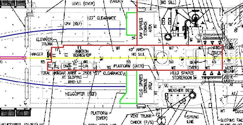 …Copied them to the model… 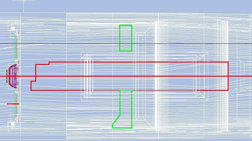 …And extruded them. Looking down on the model you can see the forward end of the added structure. 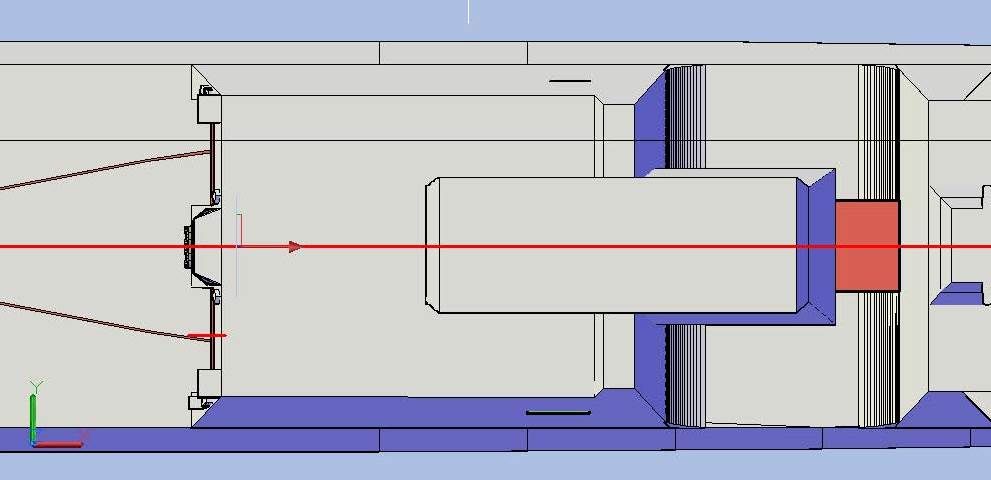 Looking into the hangar you can see the Aviation Workshop portion of the structure (red) as well as the base of the exhaust stack (cyan), and the platforms (green). 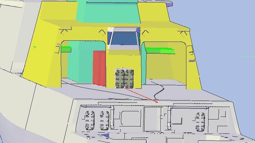 Next, I added the storage rooms, again, tracing the outlines from the plans (blue)… 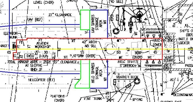 …Copying them to the plans… 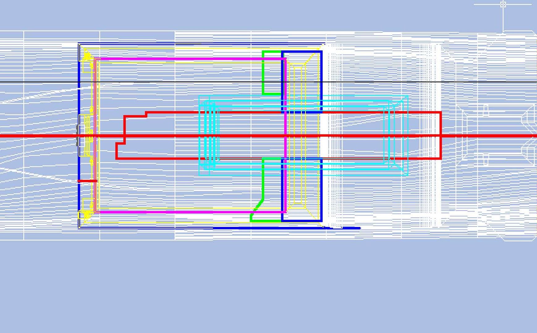 …And extruding them. 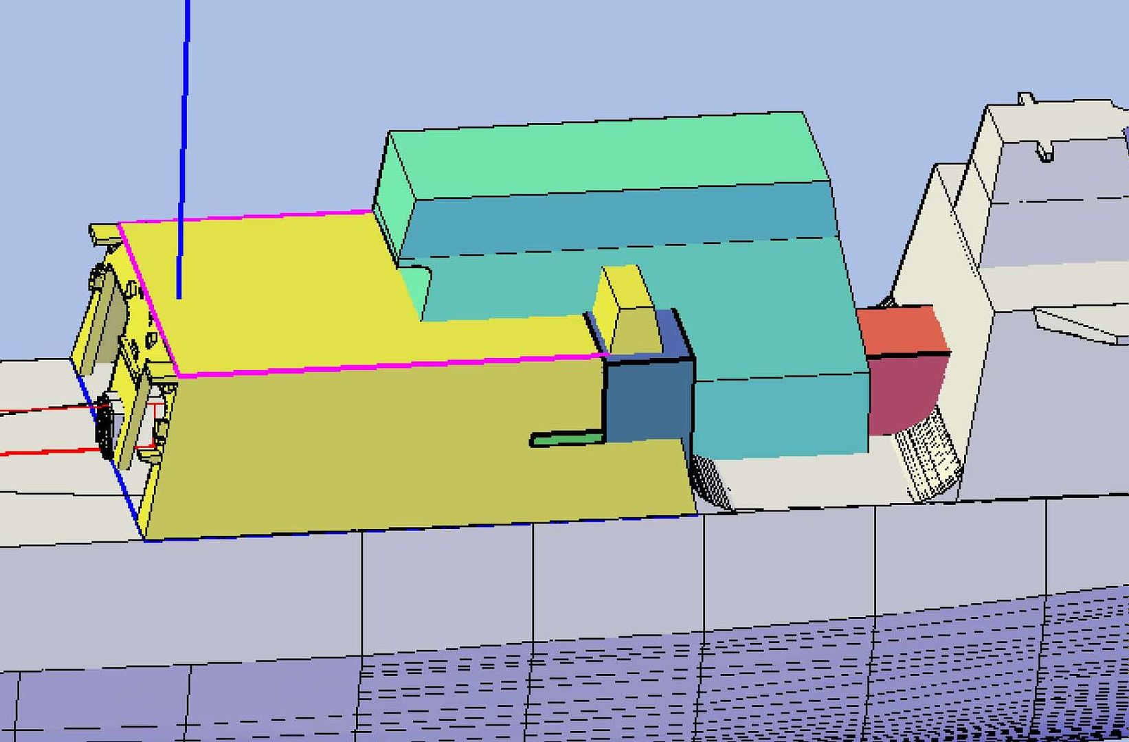 At this point, I realized that I only needed the bulkhead between the hangar and the storage rooms, so I reduced the thickness of the shape to 0.046”. Note that the bulkhead and platforms extend through the hull. This will be dealt with later. 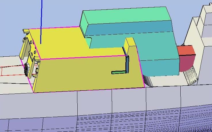 You can see it better with the hangar layer turned off, as shown in the two images below. 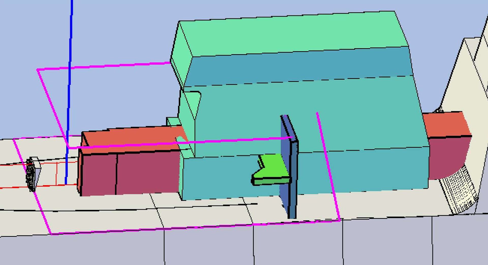 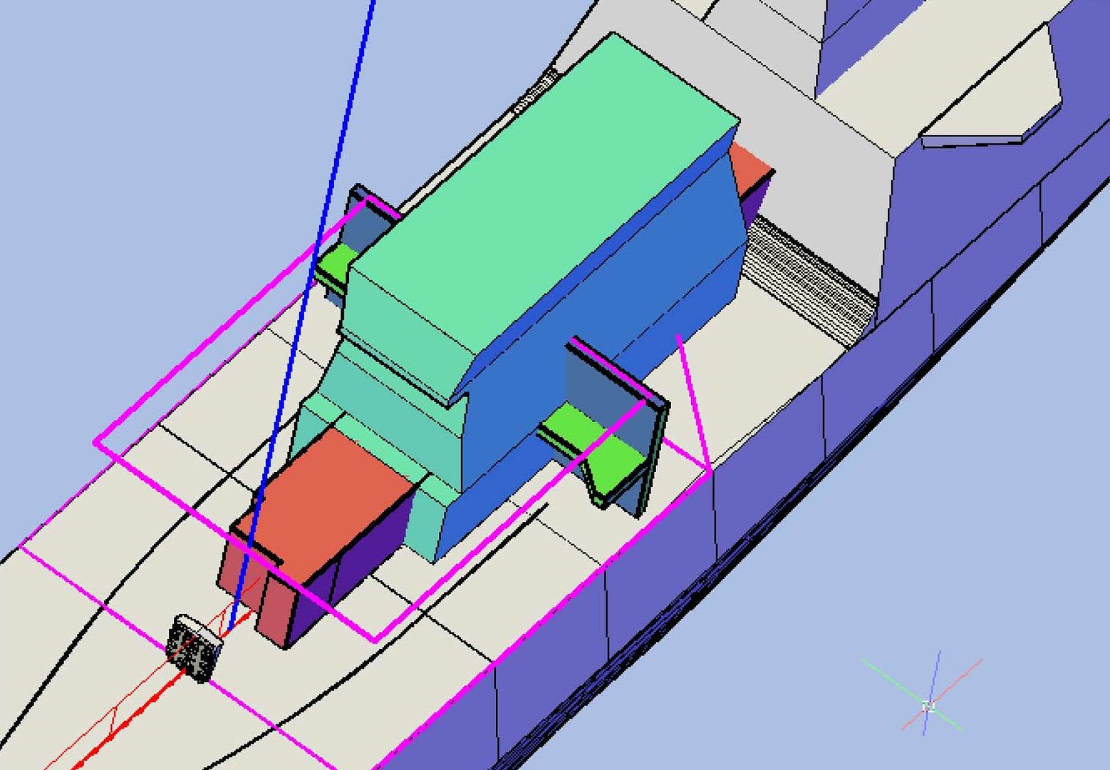 For the next steps I knew that I would be doing a series of subtractions, so I copied the parts to be involved to the side of and below the model. 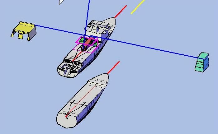 I started by slicing the newly made bulkheads and platforms (that I had joined) along the inside edge of the hull part. 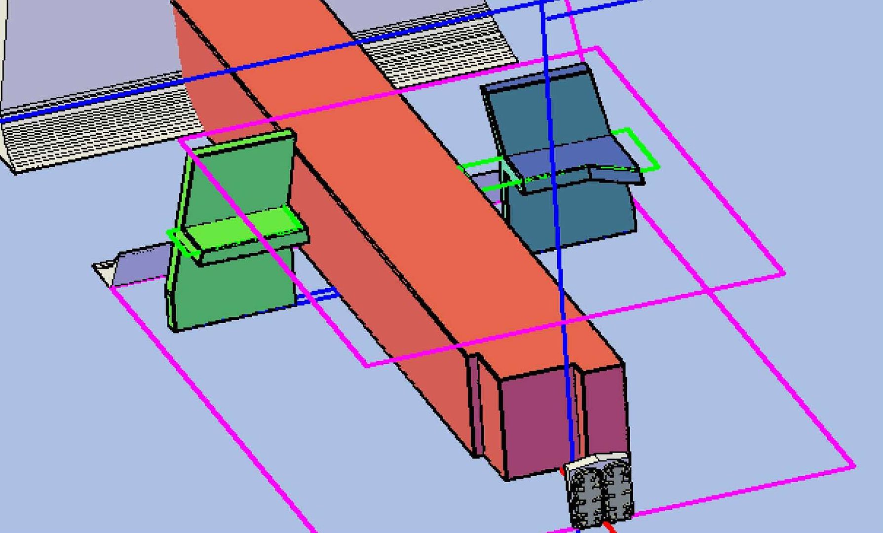 Next, I subtracted the exhaust stack from the bulkhead/platform assemblies. 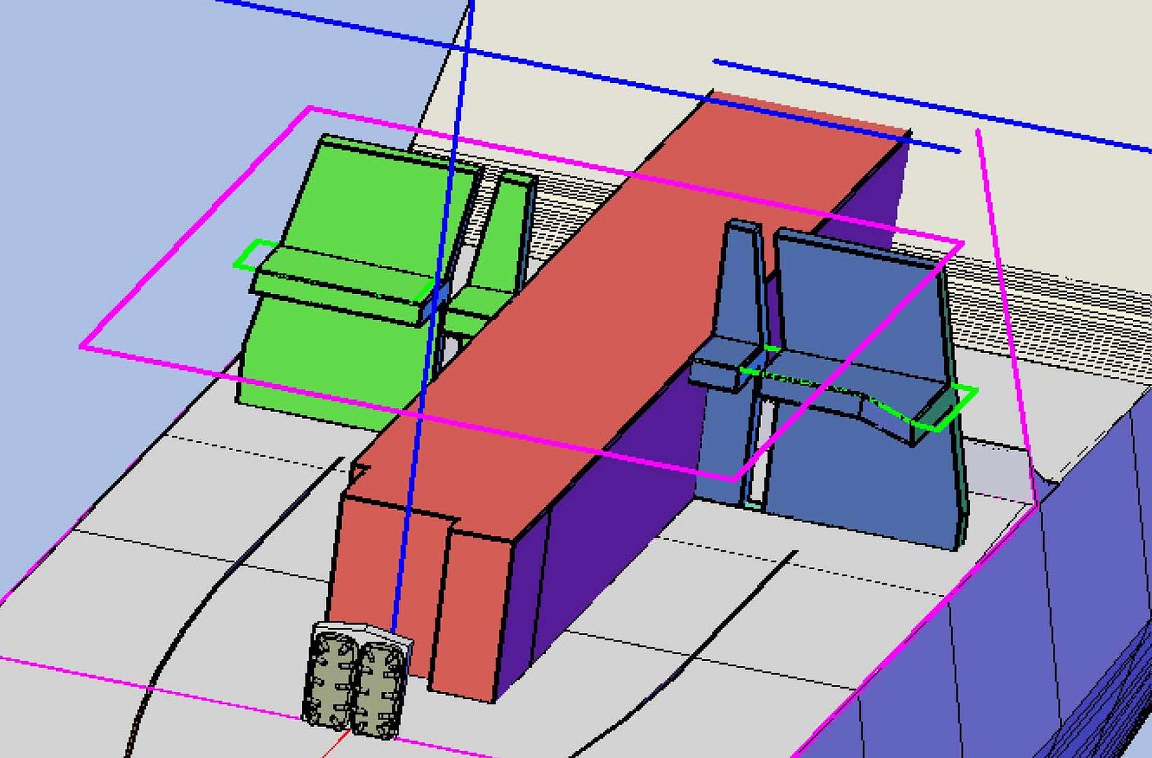 I separated the objects and deleted the unwanted objects. Then I subtracted the hangar from the bulkhead/platform assemblies. 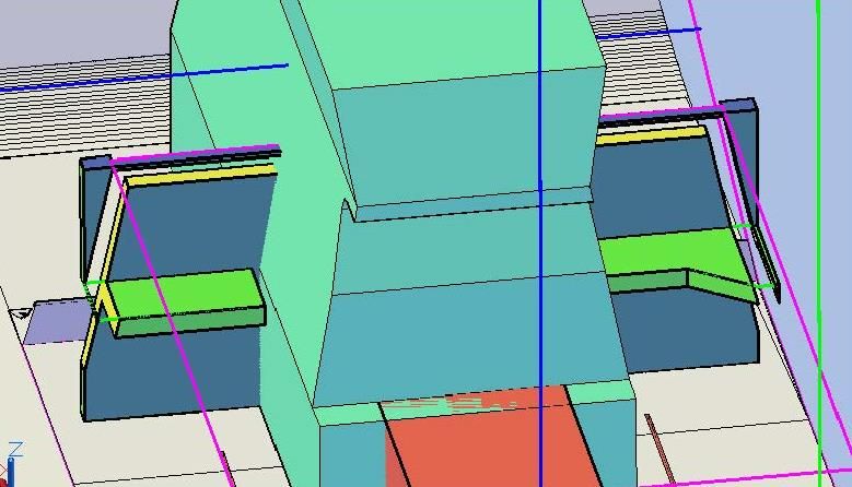 Again, separating the parts and deleted the unwanted ones. 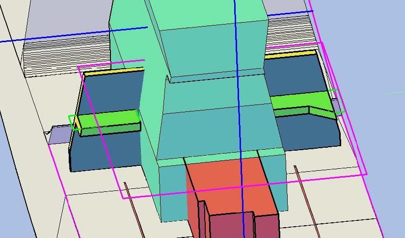 Next, I subtracted the exhaust stack from the central structure (red in the previous image), separated the pieces and deleted the unwanted ones, to create the aviation workshop (and forward corridor, to be addressed later). 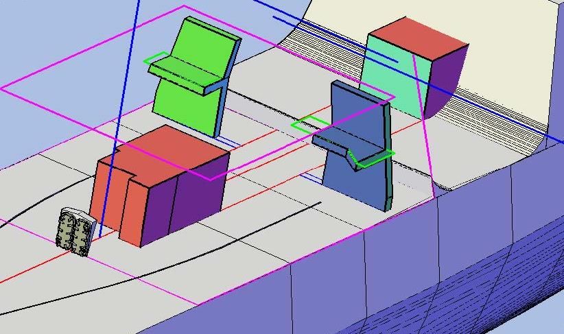 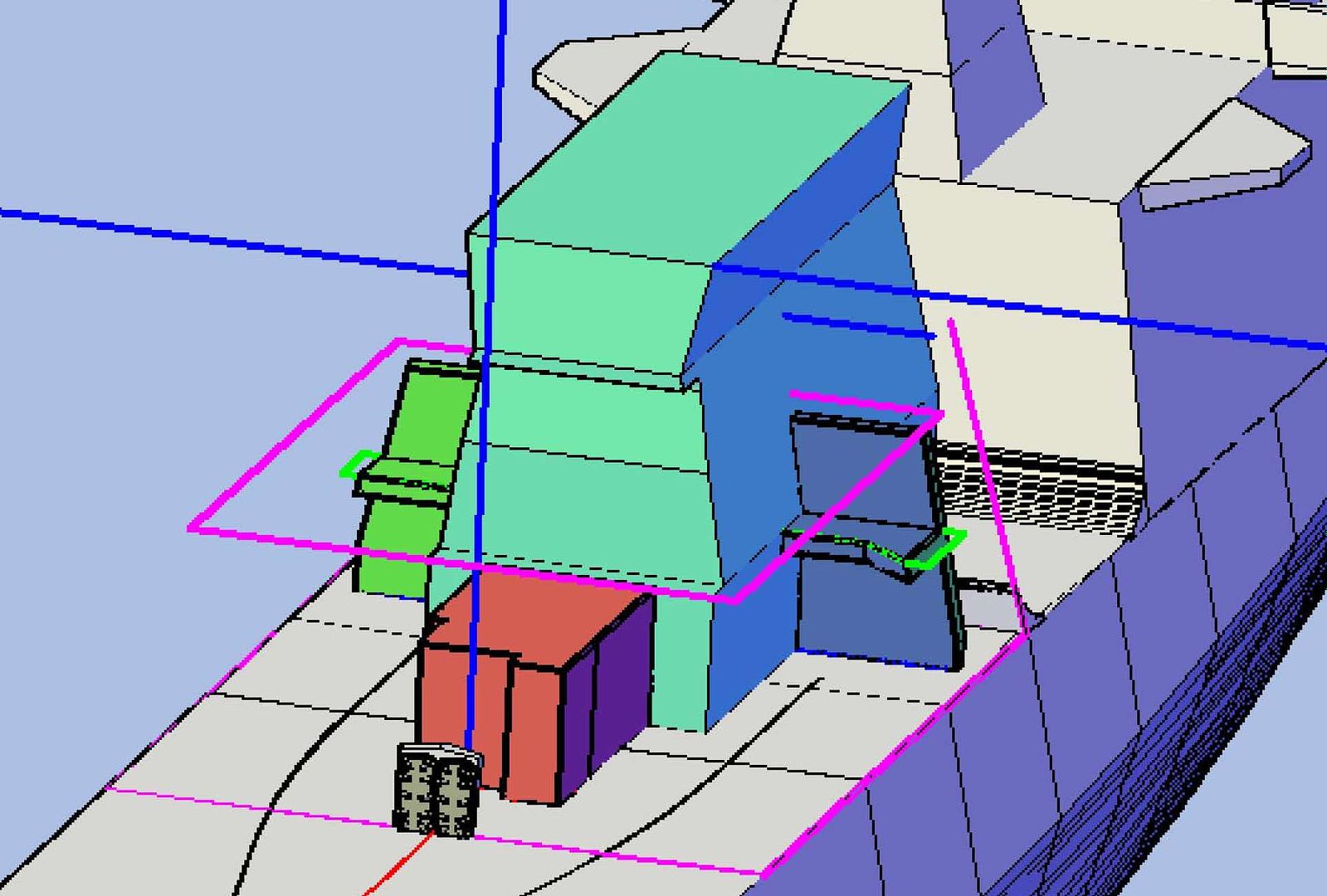 I shelled the aviation workshop to 0.046” next. 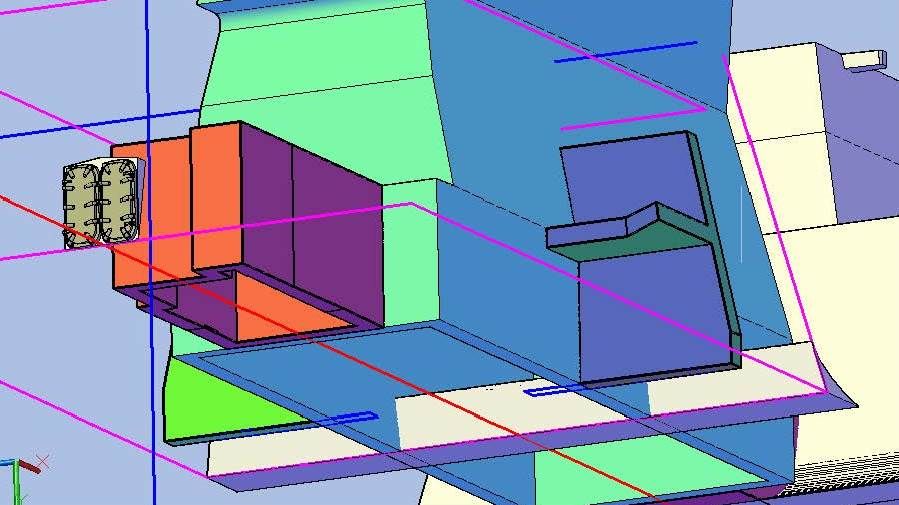 I realized here that I hadn’t extended the bulkheads out enough and their edges were lopped off, so I extended them by extruding triangles and joining them to the existing structures. 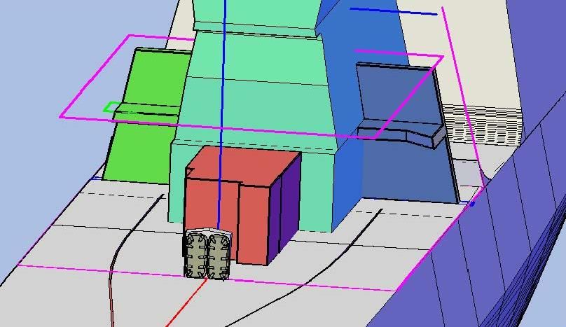 At this point I decided to make the exhaust stack to be the core piece and to wrap the hangar around it, so I subtracted the stack from the hangar... 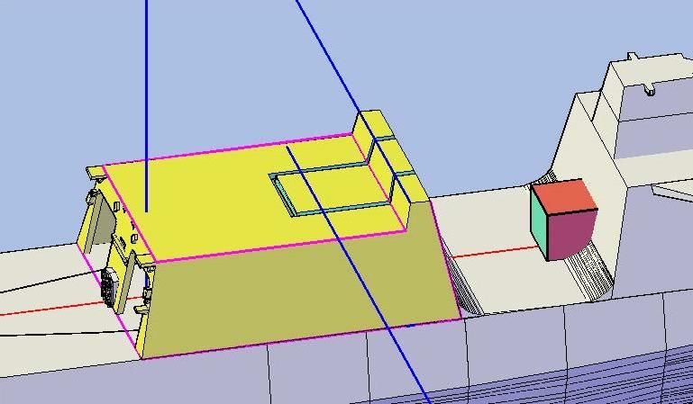 …Separated the parts and deleted the middle section. 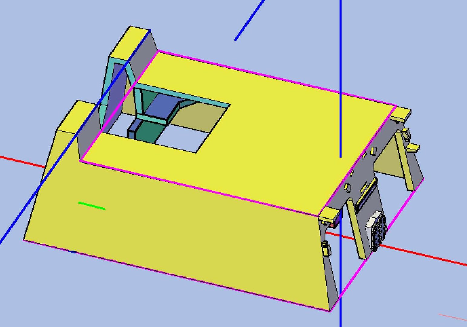 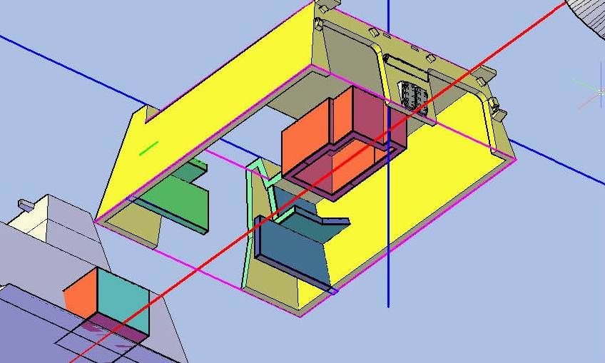 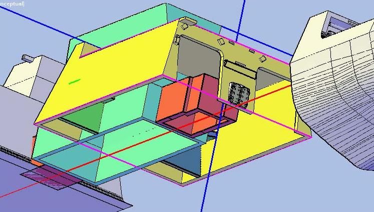 So, yesterday’s session created 5 new parts, bringing the total number of parts thus far to 134. CHEERS!!! UPDATE 44
Good Morning Brian and anybody else out there who may be following this build! :wave_1:
After taking a break from Bertholf to make some minor changes to my detailed Greenling model to prepare it for printing I decided to shift my attention inside the hangar. I started by tracing the bulkhead outline for the center structure that I will call the Aviation Workshop (red), even though it extends well forward of that, and the two platforms (green) shown on the plans…
[url=http://s1352.photobucket.com/user/rdutnell/media/USCG%20Cutter%20%20-%20Bertholf/USCGCutter-44-pix_Page_01_zpscedcddf9.jpg.html][img]http://i1352.photobucket.com/albums/q659/rdutnell/USCG%20Cutter%20%20-%20Bertholf/USCGCutter-44-pix_Page_01_zpscedcddf9.jpg[/img][/url]
…Copied them to the model…
[url=http://s1352.photobucket.com/user/rdutnell/media/USCG%20Cutter%20%20-%20Bertholf/USCGCutter-44-pix_Page_02_zps3cd919f8.jpg.html][img]http://i1352.photobucket.com/albums/q659/rdutnell/USCG%20Cutter%20%20-%20Bertholf/USCGCutter-44-pix_Page_02_zps3cd919f8.jpg[/img][/url]
…And extruded them. Looking down on the model you can see the forward end of the added structure.
[url=http://s1352.photobucket.com/user/rdutnell/media/USCG%20Cutter%20%20-%20Bertholf/USCGCutter-44-pix_Page_03_zpscd7e5a90.jpg.html][img]http://i1352.photobucket.com/albums/q659/rdutnell/USCG%20Cutter%20%20-%20Bertholf/USCGCutter-44-pix_Page_03_zpscd7e5a90.jpg[/img][/url]
Looking into the hangar you can see the Aviation Workshop portion of the structure (red) as well as the base of the exhaust stack (cyan), and the platforms (green).
[url=http://s1352.photobucket.com/user/rdutnell/media/USCG%20Cutter%20%20-%20Bertholf/USCGCutter-44-pix_Page_04_zps0d817a79.jpg.html][img]http://i1352.photobucket.com/albums/q659/rdutnell/USCG%20Cutter%20%20-%20Bertholf/USCGCutter-44-pix_Page_04_zps0d817a79.jpg[/img][/url]
Next, I added the storage rooms, again, tracing the outlines from the plans (blue)…
[url=http://s1352.photobucket.com/user/rdutnell/media/USCG%20Cutter%20%20-%20Bertholf/USCGCutter-44-pix_Page_05_zpsba5736ee.jpg.html][img]http://i1352.photobucket.com/albums/q659/rdutnell/USCG%20Cutter%20%20-%20Bertholf/USCGCutter-44-pix_Page_05_zpsba5736ee.jpg[/img][/url]
…Copying them to the plans…
[url=http://s1352.photobucket.com/user/rdutnell/media/USCG%20Cutter%20%20-%20Bertholf/USCGCutter-44-pix_Page_06_zps5f6e6fe0.jpg.html][img]http://i1352.photobucket.com/albums/q659/rdutnell/USCG%20Cutter%20%20-%20Bertholf/USCGCutter-44-pix_Page_06_zps5f6e6fe0.jpg[/img][/url]
…And extruding them.
[url=http://s1352.photobucket.com/user/rdutnell/media/USCG%20Cutter%20%20-%20Bertholf/USCGCutter-44-pix_Page_07_zps4b035d0c.jpg.html][img]http://i1352.photobucket.com/albums/q659/rdutnell/USCG%20Cutter%20%20-%20Bertholf/USCGCutter-44-pix_Page_07_zps4b035d0c.jpg[/img][/url]
At this point, I realized that I only needed the bulkhead between the hangar and the storage rooms, so I reduced the thickness of the shape to 0.046”. Note that the bulkhead and platforms extend through the hull. This will be dealt with later.
[url=http://s1352.photobucket.com/user/rdutnell/media/USCG%20Cutter%20%20-%20Bertholf/USCGCutter-44-pix_Page_08_zps10eb1ed5.jpg.html][img]http://i1352.photobucket.com/albums/q659/rdutnell/USCG%20Cutter%20%20-%20Bertholf/USCGCutter-44-pix_Page_08_zps10eb1ed5.jpg[/img][/url]
You can see it better with the hangar layer turned off, as shown in the two images below.
[url=http://s1352.photobucket.com/user/rdutnell/media/USCG%20Cutter%20%20-%20Bertholf/USCGCutter-44-pix_Page_09_zpse2f33f8f.jpg.html][img]http://i1352.photobucket.com/albums/q659/rdutnell/USCG%20Cutter%20%20-%20Bertholf/USCGCutter-44-pix_Page_09_zpse2f33f8f.jpg[/img][/url]
[url=http://s1352.photobucket.com/user/rdutnell/media/USCG%20Cutter%20%20-%20Bertholf/USCGCutter-44-pix_Page_10_zps69774e2c.jpg.html][img]http://i1352.photobucket.com/albums/q659/rdutnell/USCG%20Cutter%20%20-%20Bertholf/USCGCutter-44-pix_Page_10_zps69774e2c.jpg[/img][/url]
For the next steps I knew that I would be doing a series of subtractions, so I copied the parts to be involved to the side of and below the model.
[url=http://s1352.photobucket.com/user/rdutnell/media/USCG%20Cutter%20%20-%20Bertholf/USCGCutter-44-pix_Page_11_zps47a4ee1a.jpg.html][img]http://i1352.photobucket.com/albums/q659/rdutnell/USCG%20Cutter%20%20-%20Bertholf/USCGCutter-44-pix_Page_11_zps47a4ee1a.jpg[/img][/url]
I started by slicing the newly made bulkheads and platforms (that I had joined) along the inside edge of the hull part.
[url=http://s1352.photobucket.com/user/rdutnell/media/USCG%20Cutter%20%20-%20Bertholf/USCGCutter-44-pix_Page_12_zpsedf5640b.jpg.html][img]http://i1352.photobucket.com/albums/q659/rdutnell/USCG%20Cutter%20%20-%20Bertholf/USCGCutter-44-pix_Page_12_zpsedf5640b.jpg[/img][/url]
Next, I subtracted the exhaust stack from the bulkhead/platform assemblies.
[url=http://s1352.photobucket.com/user/rdutnell/media/USCG%20Cutter%20%20-%20Bertholf/USCGCutter-44-pix_Page_13_zps3b82bc5c.jpg.html][img]http://i1352.photobucket.com/albums/q659/rdutnell/USCG%20Cutter%20%20-%20Bertholf/USCGCutter-44-pix_Page_13_zps3b82bc5c.jpg[/img][/url]
I separated the objects and deleted the unwanted objects. Then I subtracted the hangar from the bulkhead/platform assemblies.
[url=http://s1352.photobucket.com/user/rdutnell/media/USCG%20Cutter%20%20-%20Bertholf/USCGCutter-44-pix_Page_14_zpsd9f4e7dd.jpg.html][img]http://i1352.photobucket.com/albums/q659/rdutnell/USCG%20Cutter%20%20-%20Bertholf/USCGCutter-44-pix_Page_14_zpsd9f4e7dd.jpg[/img][/url]
Again, separating the parts and deleted the unwanted ones.
[url=http://s1352.photobucket.com/user/rdutnell/media/USCG%20Cutter%20%20-%20Bertholf/USCGCutter-44-pix_Page_15_zpsbdde5330.jpg.html][img]http://i1352.photobucket.com/albums/q659/rdutnell/USCG%20Cutter%20%20-%20Bertholf/USCGCutter-44-pix_Page_15_zpsbdde5330.jpg[/img][/url]
Next, I subtracted the exhaust stack from the central structure (red in the previous image), separated the pieces and deleted the unwanted ones, to create the aviation workshop (and forward corridor, to be addressed later).
[url=http://s1352.photobucket.com/user/rdutnell/media/USCG%20Cutter%20%20-%20Bertholf/USCGCutter-44-pix_Page_16_zps31c97c37.jpg.html][img]http://i1352.photobucket.com/albums/q659/rdutnell/USCG%20Cutter%20%20-%20Bertholf/USCGCutter-44-pix_Page_16_zps31c97c37.jpg[/img][/url]
[url=http://s1352.photobucket.com/user/rdutnell/media/USCG%20Cutter%20%20-%20Bertholf/USCGCutter-44-pix_Page_17_zps80eb6cb1.jpg.html][img]http://i1352.photobucket.com/albums/q659/rdutnell/USCG%20Cutter%20%20-%20Bertholf/USCGCutter-44-pix_Page_17_zps80eb6cb1.jpg[/img][/url]
I shelled the aviation workshop to 0.046” next.
[url=http://s1352.photobucket.com/user/rdutnell/media/USCG%20Cutter%20%20-%20Bertholf/USCGCutter-44-pix_Page_18_zps69444b52.jpg.html][img]http://i1352.photobucket.com/albums/q659/rdutnell/USCG%20Cutter%20%20-%20Bertholf/USCGCutter-44-pix_Page_18_zps69444b52.jpg[/img][/url]
I realized here that I hadn’t extended the bulkheads out enough and their edges were lopped off, so I extended them by extruding triangles and joining them to the existing structures.
[url=http://s1352.photobucket.com/user/rdutnell/media/USCG%20Cutter%20%20-%20Bertholf/USCGCutter-44-pix_Page_19_zps03494140.jpg.html][img]http://i1352.photobucket.com/albums/q659/rdutnell/USCG%20Cutter%20%20-%20Bertholf/USCGCutter-44-pix_Page_19_zps03494140.jpg[/img][/url]
At this point I decided to make the exhaust stack to be the core piece and to wrap the hangar around it, so I subtracted the stack from the hangar...
[url=http://s1352.photobucket.com/user/rdutnell/media/USCG%20Cutter%20%20-%20Bertholf/USCGCutter-44-pix_Page_20_zps60aba8cc.jpg.html][img]http://i1352.photobucket.com/albums/q659/rdutnell/USCG%20Cutter%20%20-%20Bertholf/USCGCutter-44-pix_Page_20_zps60aba8cc.jpg[/img][/url]
…Separated the parts and deleted the middle section.
[url=http://s1352.photobucket.com/user/rdutnell/media/USCG%20Cutter%20%20-%20Bertholf/USCGCutter-44-pix_Page_21_zpsb8e27a5b.jpg.html][img]http://i1352.photobucket.com/albums/q659/rdutnell/USCG%20Cutter%20%20-%20Bertholf/USCGCutter-44-pix_Page_21_zpsb8e27a5b.jpg[/img][/url]
[url=http://s1352.photobucket.com/user/rdutnell/media/USCG%20Cutter%20%20-%20Bertholf/USCGCutter-44-pix_Page_22_zpsf00d6d80.jpg.html][img]http://i1352.photobucket.com/albums/q659/rdutnell/USCG%20Cutter%20%20-%20Bertholf/USCGCutter-44-pix_Page_22_zpsf00d6d80.jpg[/img][/url]
[url=http://s1352.photobucket.com/user/rdutnell/media/USCG%20Cutter%20%20-%20Bertholf/USCGCutter-44-pix_Page_24_zpsb32472a0.jpg.html][img]http://i1352.photobucket.com/albums/q659/rdutnell/USCG%20Cutter%20%20-%20Bertholf/USCGCutter-44-pix_Page_24_zpsb32472a0.jpg[/img][/url]
So, yesterday’s session created 5 new parts, bringing the total number of parts thus far to 134.
CHEERS!!!
:wave_1:
|
|
|
|
Posted: Tue Jul 16, 2013 6:59 am |
|
|
|
|
|
| |
Post subject: |
Re: USCGC Bertholf (WMSL-750) – A CAD Design for 3D Printing |
|
|
The current model is for 1/350. 1/700 will follow.
:wave_1:
The current model is for 1/350. 1/700 will follow.
|
|
|
|
Posted: Sat Jul 13, 2013 12:05 pm |
|
|
|
|
|
| |
Post subject: |
Re: USCGC Bertholf (WMSL-750) – A CAD Design for 3D Printing |
|
|
|
Yep I'm following.....There is so much information plus I have only dabbled in CAD. I may have missed it....what scale were you going to print this out in?
Yep I'm following.....There is so much information plus I have only dabbled in CAD. I may have missed it....what scale were you going to print this out in?
|
|
|
|
Posted: Sat Jul 13, 2013 10:16 am |
|
|
|
|
|
| |
Post subject: |
Re: USCGC Bertholf (WMSL-750) – A CAD Design for 3D Printing |
|
|
UPDATE 43Good Morning guys! Busy day yesterday. I did some modeling but didn’t have time to post it. I didn’t do a lot, but I did prepare some of the latest additions for attaching to the ship. Other parts, I simply “Union”-ed with the main model. First, soon after making the safety nets, I saved them to a separate file and deleted them from my model. They used as much file space as the rest of the model, and when the file gets too big, it really slows the program down. I can always simply copy them back for “photo ops” and delete them again for working on the model. Anyway, on to yesterday’s modeling. I started with the Helo Deck containers. Since these are not permanent fixtures of the ship, I do not intend to provide a mounting place on the deck for them, so that the modeler can do with them as they please, but I wanted to provide a base so that they would be easier to mount upright and not slanted. I did this by extruding a rectangle out of the container, flush with the bottom. I didn’t want the base to be obvious to the viewer, so I made the base fairly narrow. Still, I think that some base is better than no base. 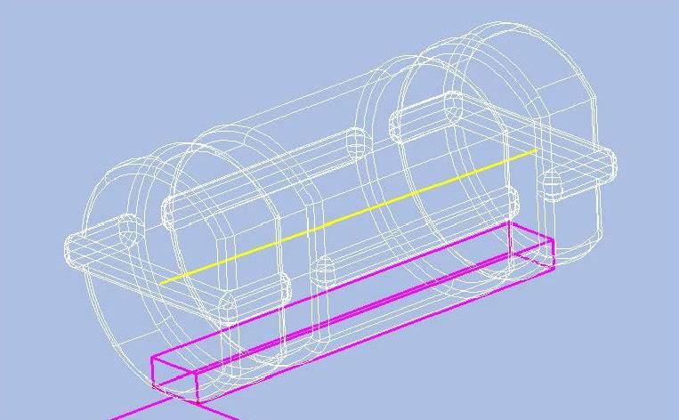 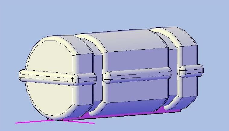 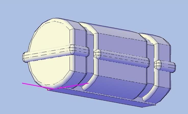 To mount the Aviation Control Station (ACS), I again used extruded rectangles, I don’t know why, I just did. In hindsight, the spheres I used for objects on the deck would have worked just as well, but so be it. I used three rectangles, two shorter ones at the top, and a longer one at the bottom. All three were extruded 0.020” out from the surface. The top two are 0.054” long and 0.02” wide. The bottom one is 0.108” long and 0.02” wide. 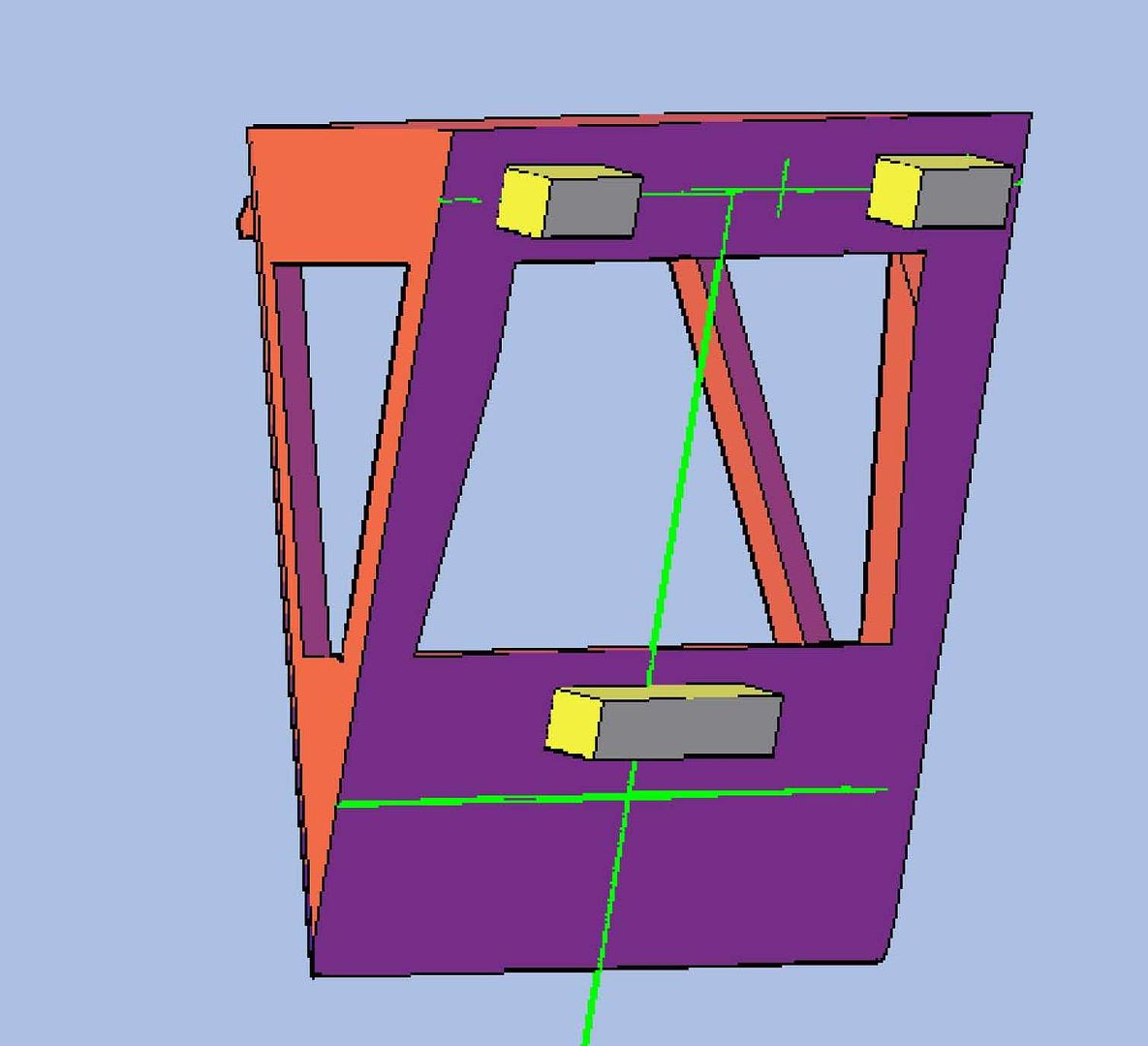 All three extruded rectangles were then joined to the ACS. 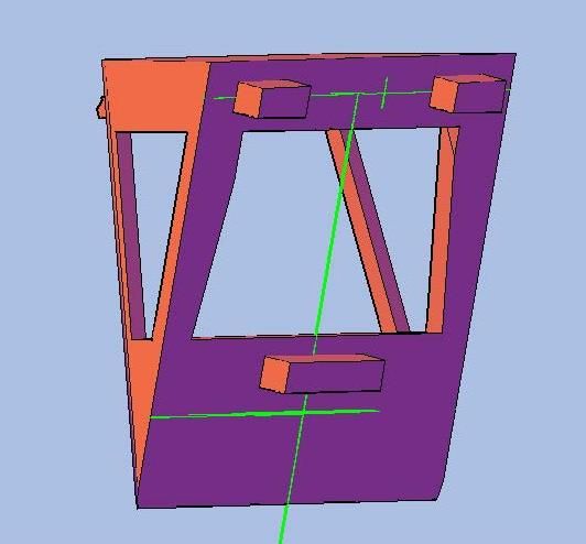 For the ship side I extruded rectangles into the surface 0.020”. The rectangles I extruded to make the cuts into the model were 0.056” long and 0.022” long. The bottom one was 0.110” long and 0.022” wide. These are green in the image below. 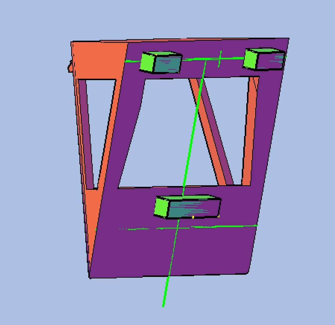 At this point, it occurred to me that the 3D printer would not like the sharp point at the bottom of the ACS, so I sliced it off. 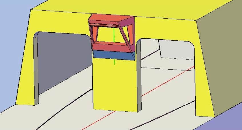 I then joined the bottom part to the hangar part and subtracted the extruded rectangles. 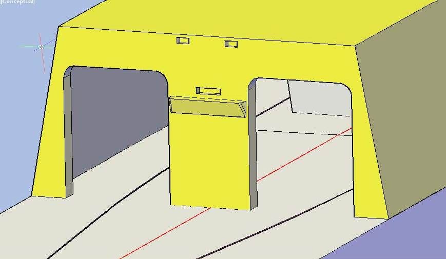 After much thought, I decide to make the other features part of the hangar part, so I joined them. I did not join the door and frame however, because I am still not sure if I have it correct. 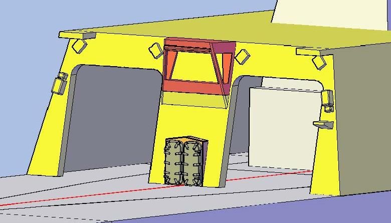 Anyway, here is what it looks like with the doors in the open position. 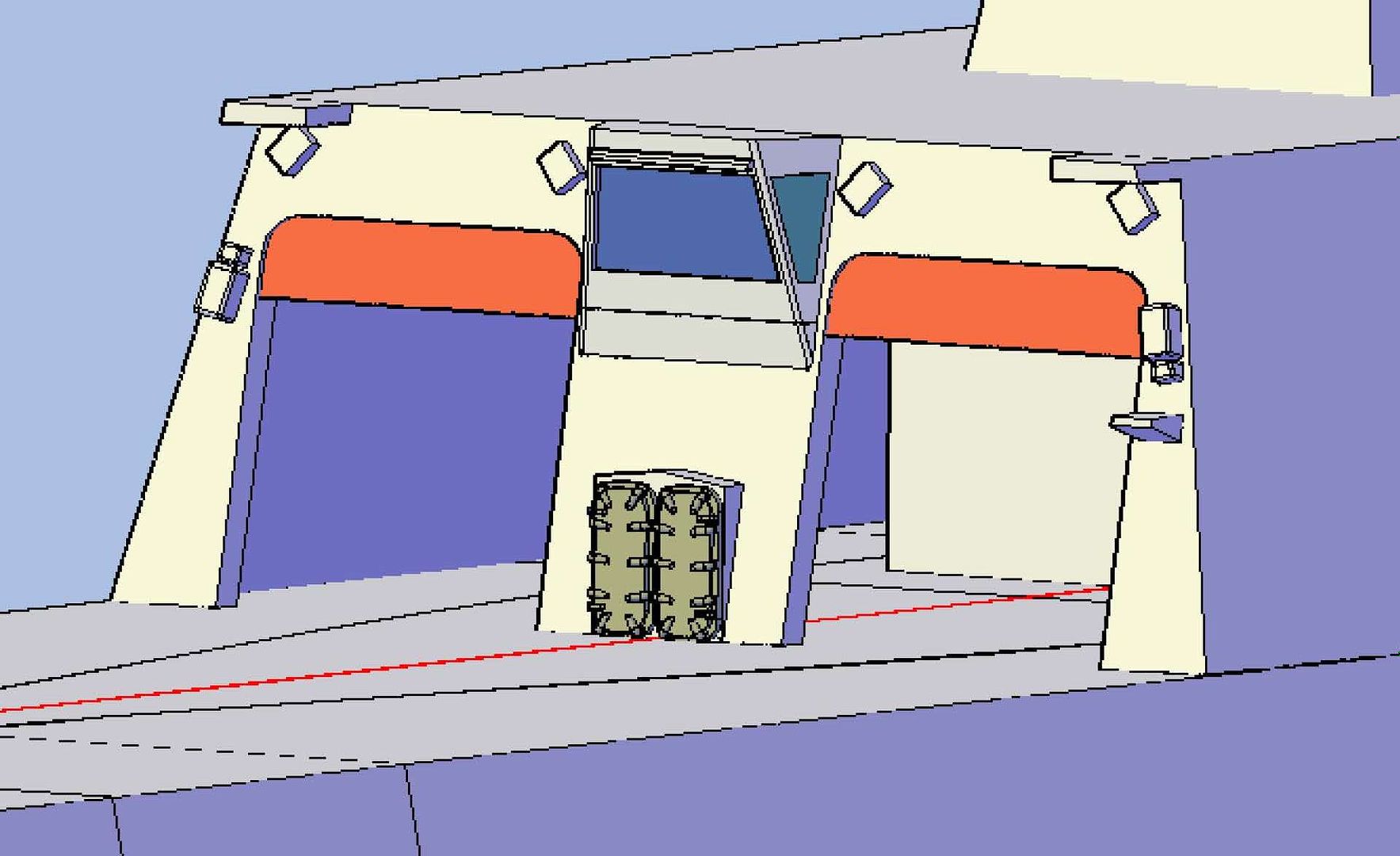 Note that the inside is incomplete. That’s what I’m going to play with next. I want to know though, is there anybody out there following this build? If not, I am considering not posting it any more. I post mostly for feedback and since I haven’t been getting any, I’m thinking that I may be wasting time that I could spend modeling. If I don’t hear anything, it’s been fun. CHEERS!!!
[u][b]UPDATE 43[/b][/u]
Good Morning guys! :wave_1:
Busy day yesterday. I did some modeling but didn’t have time to post it. I didn’t do a lot, but I did prepare some of the latest additions for attaching to the ship. Other parts, I simply “Union”-ed with the main model.
First, soon after making the safety nets, I saved them to a separate file and deleted them from my model. They used as much file space as the rest of the model, and when the file gets too big, it really slows the program down. I can always simply copy them back for “photo ops” and delete them again for working on the model.
Anyway, on to yesterday’s modeling. I started with the Helo Deck containers. Since these are not permanent fixtures of the ship, I do not intend to provide a mounting place on the deck for them, so that the modeler can do with them as they please, but I wanted to provide a base so that they would be easier to mount upright and not slanted. I did this by extruding a rectangle out of the container, flush with the bottom. I didn’t want the base to be obvious to the viewer, so I made the base fairly narrow. Still, I think that some base is better than no base.
[url=http://s1352.photobucket.com/user/rdutnell/media/USCG%20Cutter%20%20-%20Bertholf/USCGCutter-43-pix_Page_01_zps2c43f30d.jpg.html][img]http://i1352.photobucket.com/albums/q659/rdutnell/USCG%20Cutter%20%20-%20Bertholf/USCGCutter-43-pix_Page_01_zps2c43f30d.jpg[/img][/url]
[url=http://s1352.photobucket.com/user/rdutnell/media/USCG%20Cutter%20%20-%20Bertholf/USCGCutter-43-pix_Page_02_zpse9d1f784.jpg.html][img]http://i1352.photobucket.com/albums/q659/rdutnell/USCG%20Cutter%20%20-%20Bertholf/USCGCutter-43-pix_Page_02_zpse9d1f784.jpg[/img][/url]
[url=http://s1352.photobucket.com/user/rdutnell/media/USCG%20Cutter%20%20-%20Bertholf/USCGCutter-43-pix_Page_03_zpscc158b8e.jpg.html][img]http://i1352.photobucket.com/albums/q659/rdutnell/USCG%20Cutter%20%20-%20Bertholf/USCGCutter-43-pix_Page_03_zpscc158b8e.jpg[/img][/url]
To mount the Aviation Control Station (ACS), I again used extruded rectangles, I don’t know why, I just did. In hindsight, the spheres I used for objects on the deck would have worked just as well, but so be it. I used three rectangles, two shorter ones at the top, and a longer one at the bottom. All three were extruded 0.020” out from the surface. The top two are 0.054” long and 0.02” wide. The bottom one is 0.108” long and 0.02” wide.
[url=http://s1352.photobucket.com/user/rdutnell/media/USCG%20Cutter%20%20-%20Bertholf/USCGCutter-43-pix_Page_04_zps3285e920.jpg.html][img]http://i1352.photobucket.com/albums/q659/rdutnell/USCG%20Cutter%20%20-%20Bertholf/USCGCutter-43-pix_Page_04_zps3285e920.jpg[/img][/url]
All three extruded rectangles were then joined to the ACS.
[url=http://s1352.photobucket.com/user/rdutnell/media/USCG%20Cutter%20%20-%20Bertholf/USCGCutter-43-pix_Page_05_zps317b853f.jpg.html][img]http://i1352.photobucket.com/albums/q659/rdutnell/USCG%20Cutter%20%20-%20Bertholf/USCGCutter-43-pix_Page_05_zps317b853f.jpg[/img][/url]
For the ship side I extruded rectangles into the surface 0.020”. The rectangles I extruded to make the cuts into the model were 0.056” long and 0.022” long. The bottom one was 0.110” long and 0.022” wide. These are green in the image below.
[url=http://s1352.photobucket.com/user/rdutnell/media/USCG%20Cutter%20%20-%20Bertholf/USCGCutter-43-pix_Page_06_zps128cdf76.jpg.html][img]http://i1352.photobucket.com/albums/q659/rdutnell/USCG%20Cutter%20%20-%20Bertholf/USCGCutter-43-pix_Page_06_zps128cdf76.jpg[/img][/url]
At this point, it occurred to me that the 3D printer would not like the sharp point at the bottom of the ACS, so I sliced it off.
[url=http://s1352.photobucket.com/user/rdutnell/media/USCG%20Cutter%20%20-%20Bertholf/USCGCutter-43-pix_Page_07_zpsca6ae384.jpg.html][img]http://i1352.photobucket.com/albums/q659/rdutnell/USCG%20Cutter%20%20-%20Bertholf/USCGCutter-43-pix_Page_07_zpsca6ae384.jpg[/img][/url]
I then joined the bottom part to the hangar part and subtracted the extruded rectangles.
[url=http://s1352.photobucket.com/user/rdutnell/media/USCG%20Cutter%20%20-%20Bertholf/USCGCutter-43-pix_Page_08_zps9bd210da.jpg.html][img]http://i1352.photobucket.com/albums/q659/rdutnell/USCG%20Cutter%20%20-%20Bertholf/USCGCutter-43-pix_Page_08_zps9bd210da.jpg[/img][/url]
After much thought, I decide to make the other features part of the hangar part, so I joined them. I did not join the door and frame however, because I am still not sure if I have it correct.
[url=http://s1352.photobucket.com/user/rdutnell/media/USCG%20Cutter%20%20-%20Bertholf/USCGCutter-43-pix_Page_10_zps011f2d7a.jpg.html][img]http://i1352.photobucket.com/albums/q659/rdutnell/USCG%20Cutter%20%20-%20Bertholf/USCGCutter-43-pix_Page_10_zps011f2d7a.jpg[/img][/url]
Anyway, here is what it looks like with the doors in the open position.
[url=http://s1352.photobucket.com/user/rdutnell/media/USCG%20Cutter%20%20-%20Bertholf/USCGCutter-43-pix_Page_11_zps2be7df76.jpg.html][img]http://i1352.photobucket.com/albums/q659/rdutnell/USCG%20Cutter%20%20-%20Bertholf/USCGCutter-43-pix_Page_11_zps2be7df76.jpg[/img][/url]
Note that the inside is incomplete. That’s what I’m going to play with next.
I want to know though, is there anybody out there following this build? If not, I am considering not posting it any more. I post mostly for feedback and since I haven’t been getting any, I’m thinking that I may be wasting time that I could spend modeling. If I don’t hear anything, it’s been fun.
CHEERS!!!
|
|
|
|
Posted: Fri Jul 12, 2013 5:52 am |
|
|
|
|


