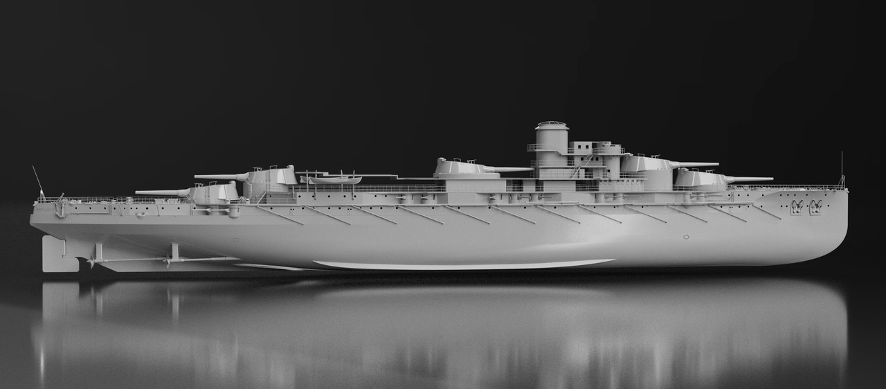
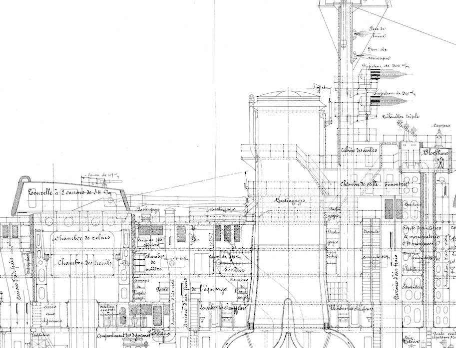
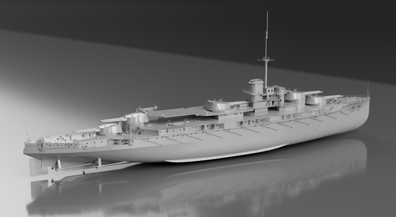
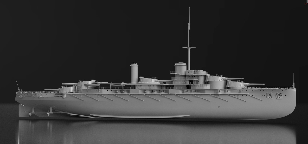
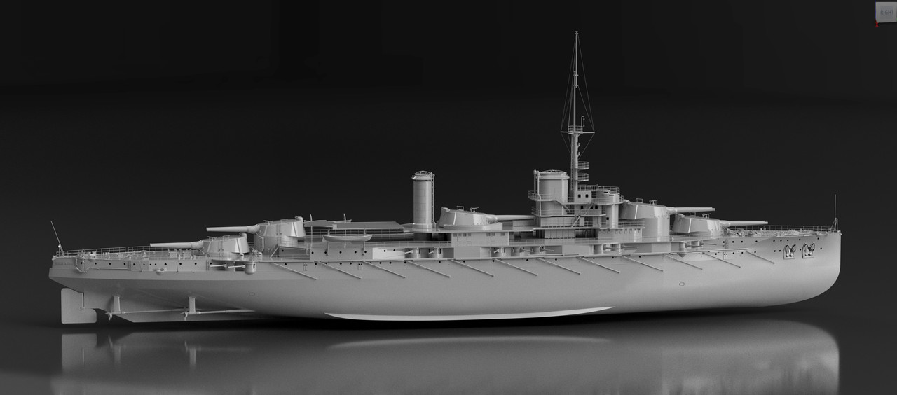
Some pictures to show the progress of this complex project, where before drawing, it is necessary to think and analyze well, to read the multitude of plans and pictures of this ship and the two others to decipher the reality of things as for this ship in 1916.
In short, one can think of wasting time looking at a hundred photos in a loop and think that one is going to miss something.
This is not the case, visual memory is important in the process of assimilation of the environment. It takes time to adapt to feel a little "at home".
And everything falls into place little by little in spite of sketchy information sometimes, in particular on the superstructures badly documented for the blow in spite of the plans.
The photos and the plans are complementary and rectify each other with respect to the reality at a certain moment.
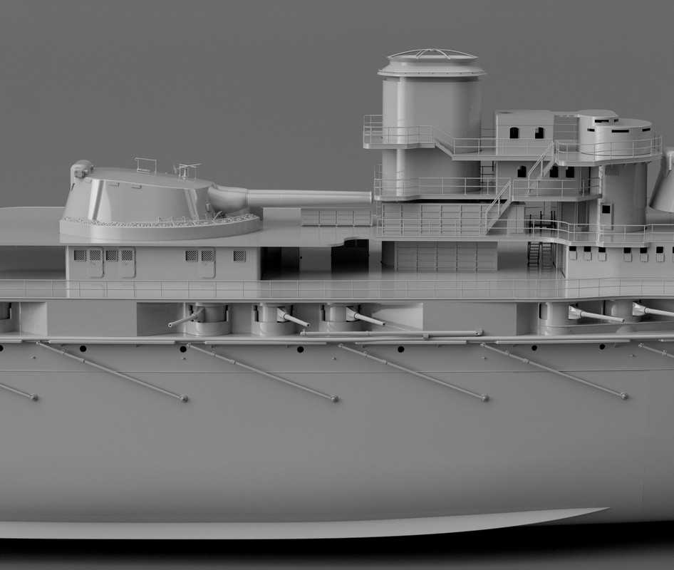
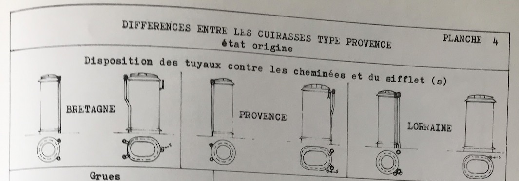
I'm not talking again about the difference in the placement of elements between the original plans, chimneys, bridge, turrets. the waltz of compromises, I got used to.
I've been spending more time analyzing than drawing lately. But it's still fun.
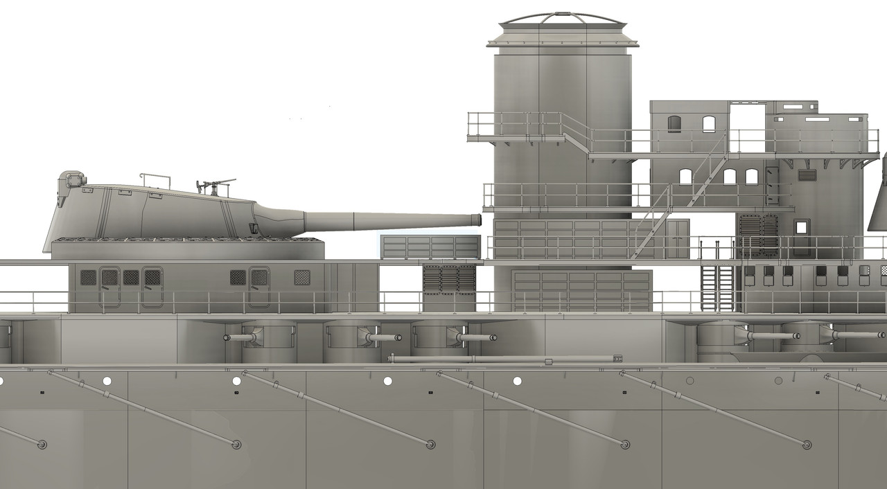
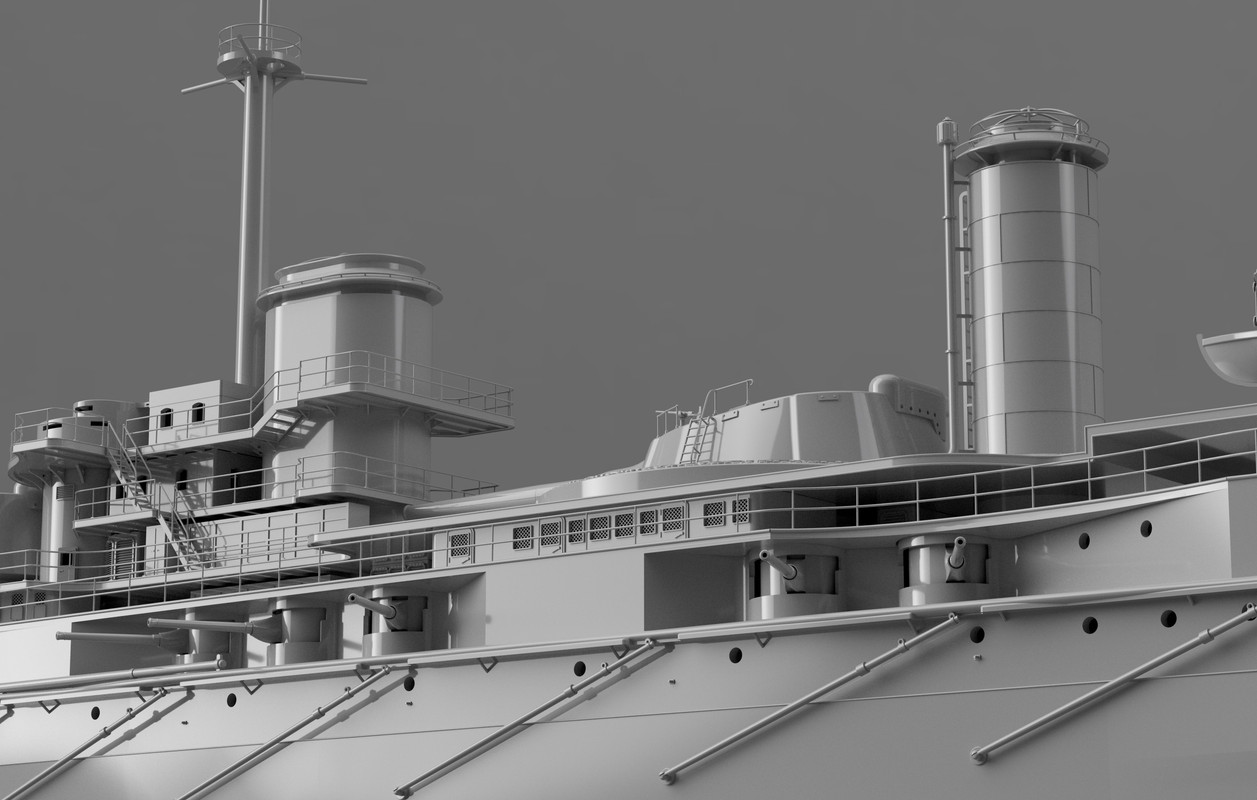
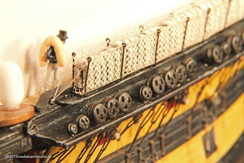
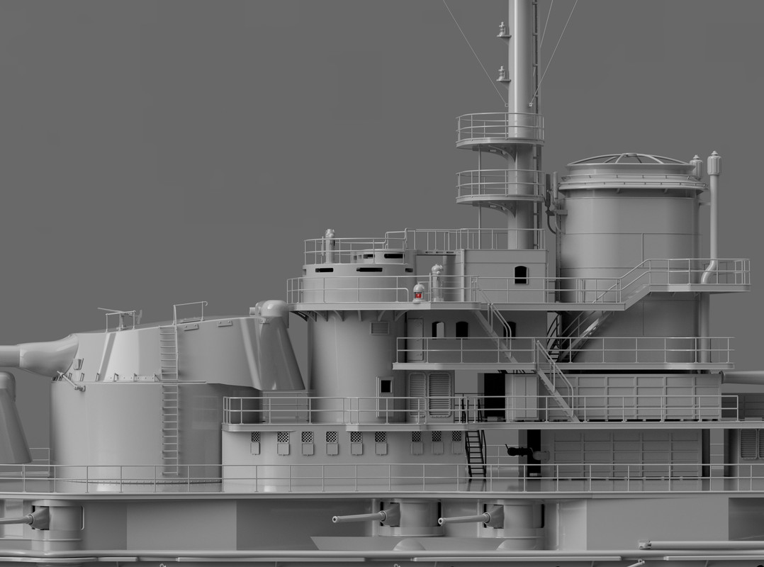
The "railings/parapet " (inherited from the old sailboat) are present everywhere on this ship, here the word has another meaning, more used nowadays:
Internet portal "The Dictionary n. (Navy) (Aged) A parapet that was formed around the upper deck of a ship, with the crew's hammocks, to protect against the enemy's musketry and small machine gun. n. (Navy) Today, guardrail, parapet around the upper deck of a ship. n. (Navy) Bulkhead where the crew's hammocks are placed during the day. It is mostly used in the plural to designate the whole of these caissons. n. (By extension) (Navy) Wall of a ship.
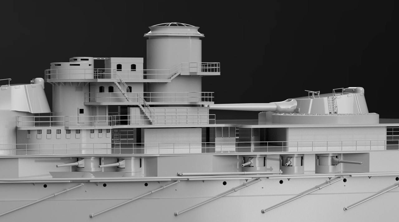
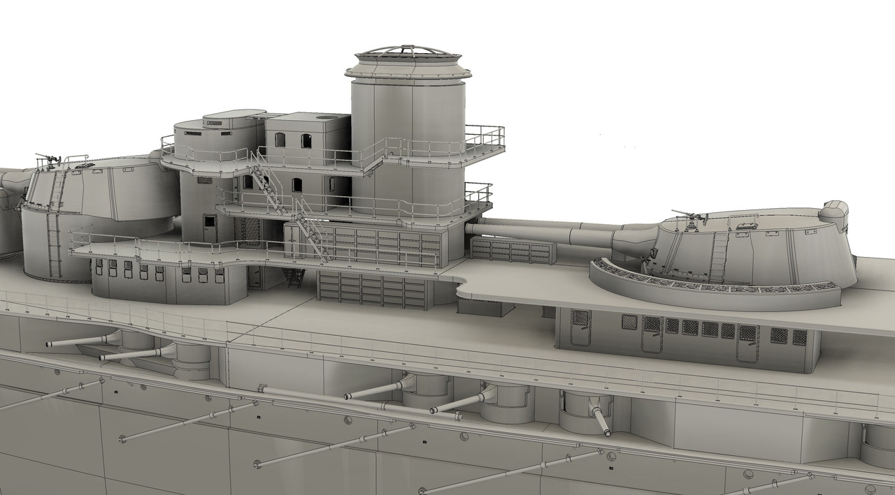
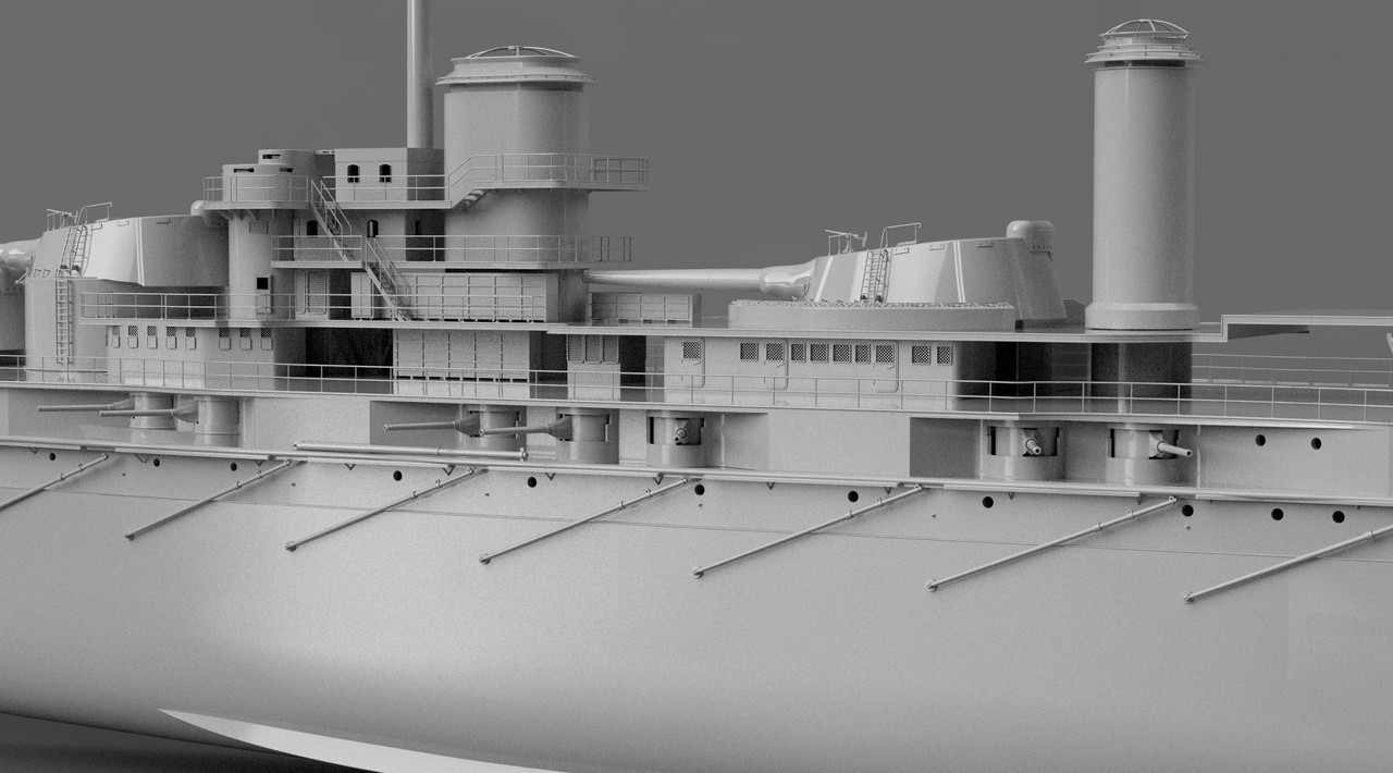
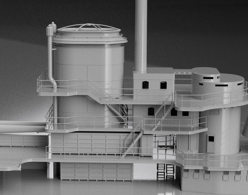
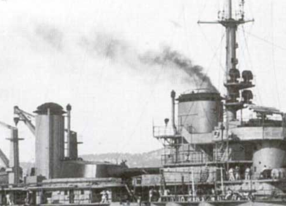
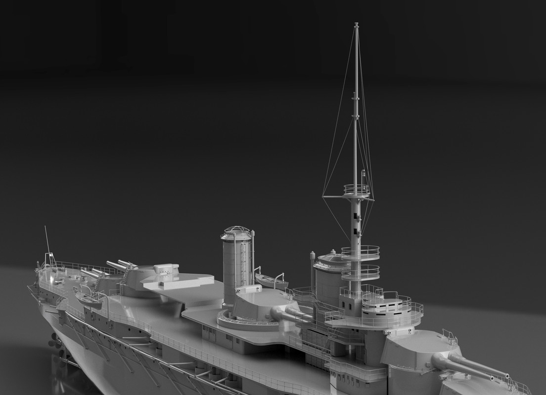
I'm still focused on the central part of the first and second deck, at the turret level, the bakery on starboard and the crew's galley on port.
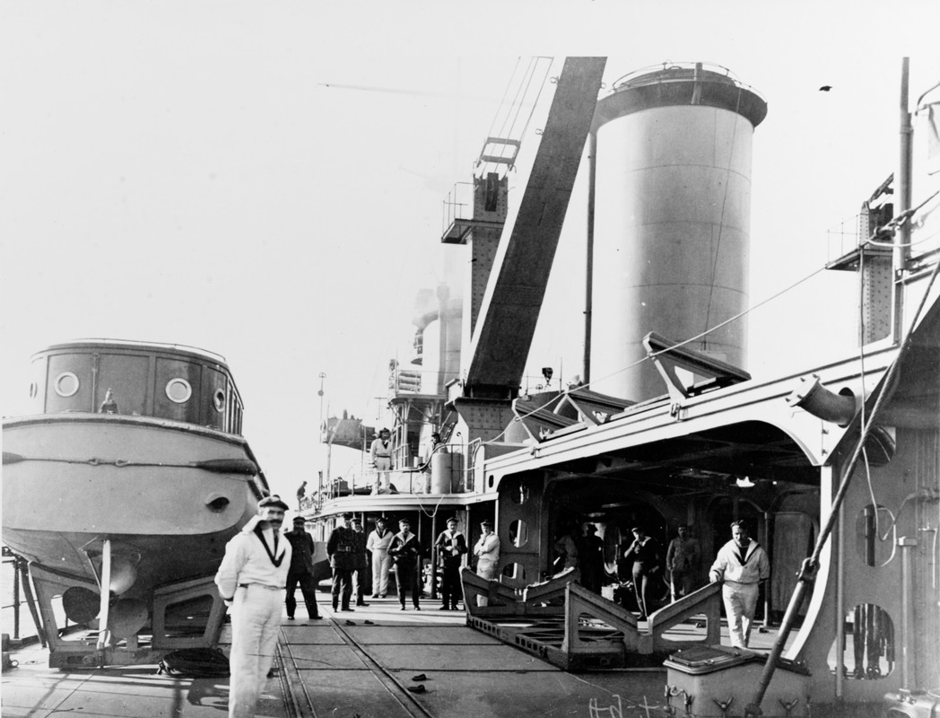
I also drew the sketch of the aft stack.
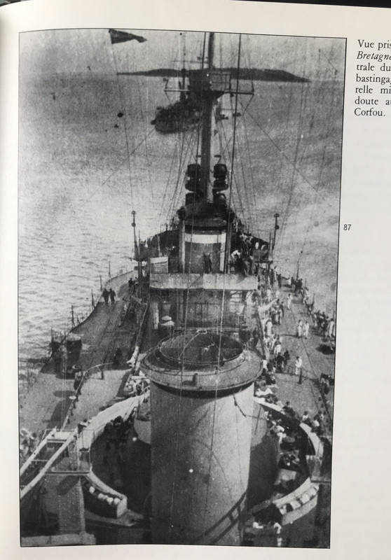
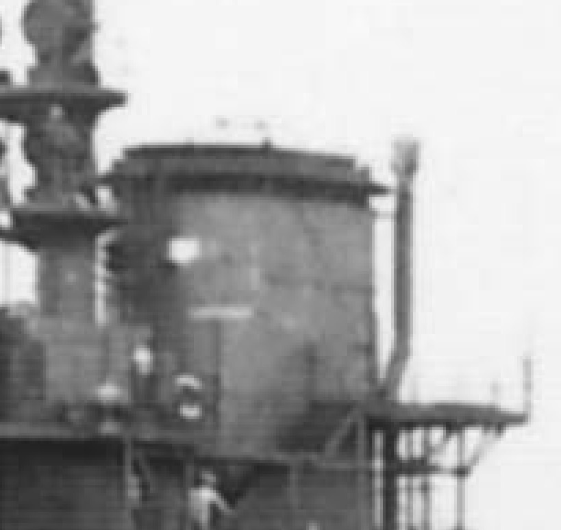
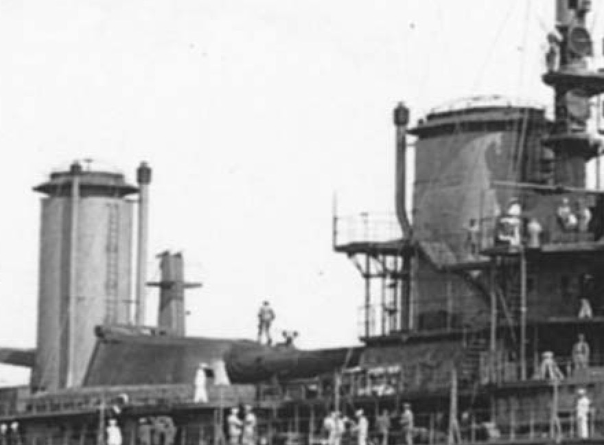
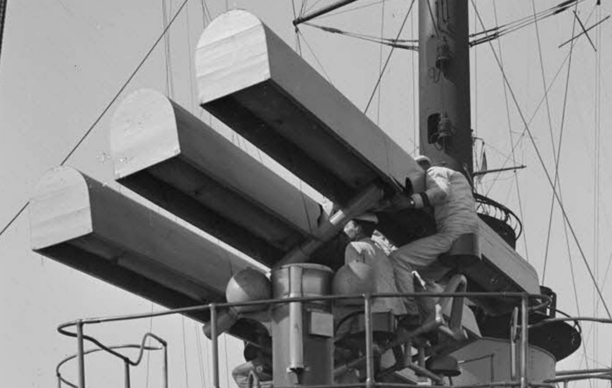
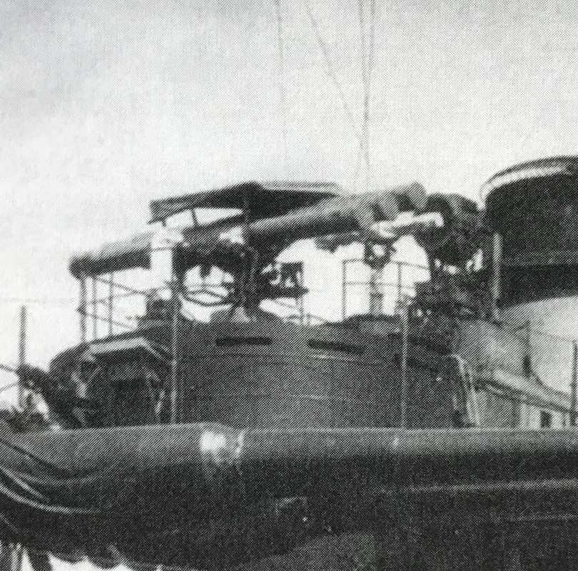
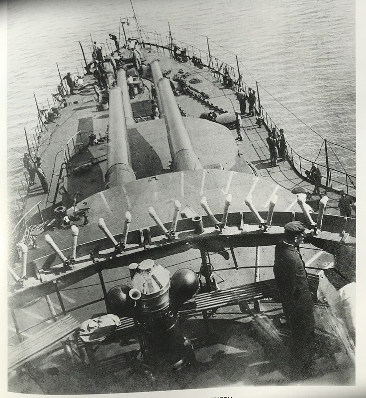
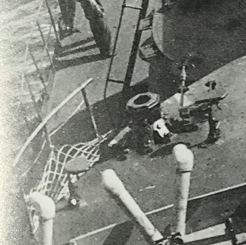
The photo taken from the top of the aft mature is extremely rare for the time and very useful, you can see the protections around the turret and many other things, to my knowledge it is the only photo of the second deck.
Joined: Sun Mar 07, 2010 12:01 am Posts: 1677 Location: Corvallis, Oregon, USA
Pascal,
I am curious about the circular feature around the base of the midships turret - I think you called it the "bridge bunker." It appears to be a series of storage compartments, with a dozen cylindrical objects loosely stowed in each compartment.
What are these things?
Phil
_________________ A collision at sea will ruin your entire day. Aristotle
It is a protection against grapeshot or shrapnel, these containers are filled by the hammocks of the crew. There are also some around the front superstructures. It already existed on the old sailing warships, I don't have the right term in English, in French is "bastingage".
For the printing I am rather confident, as the projects go on, we foresee the things during the drawing and we avoid the known stupidities if possible.
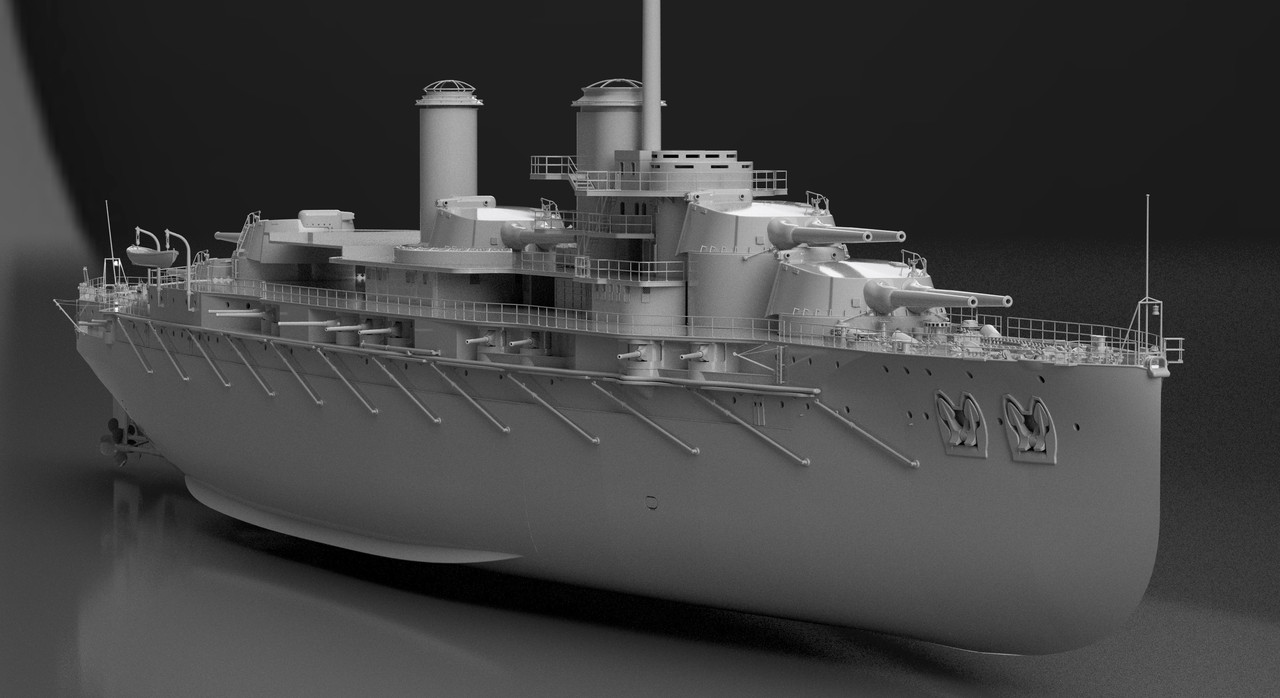
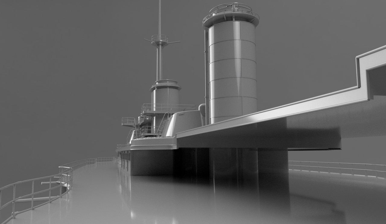
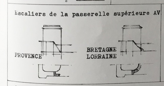
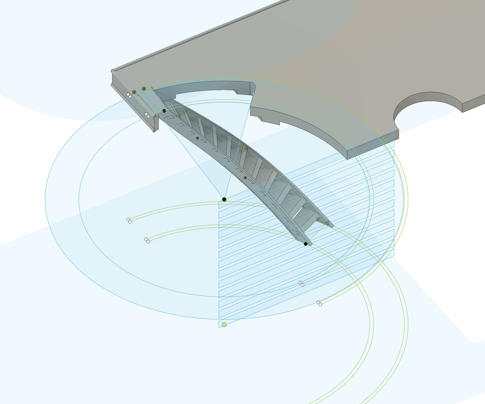
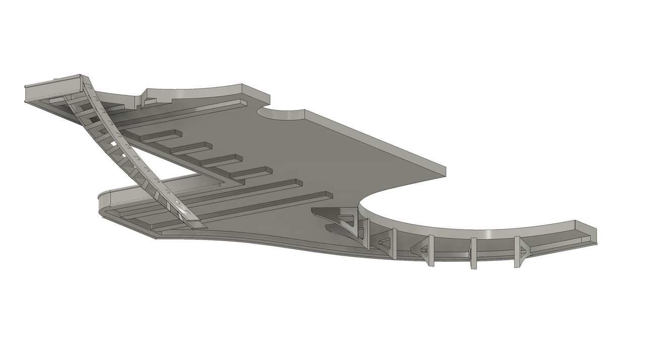
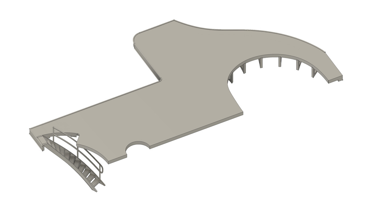
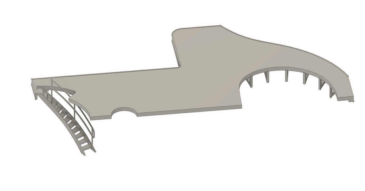
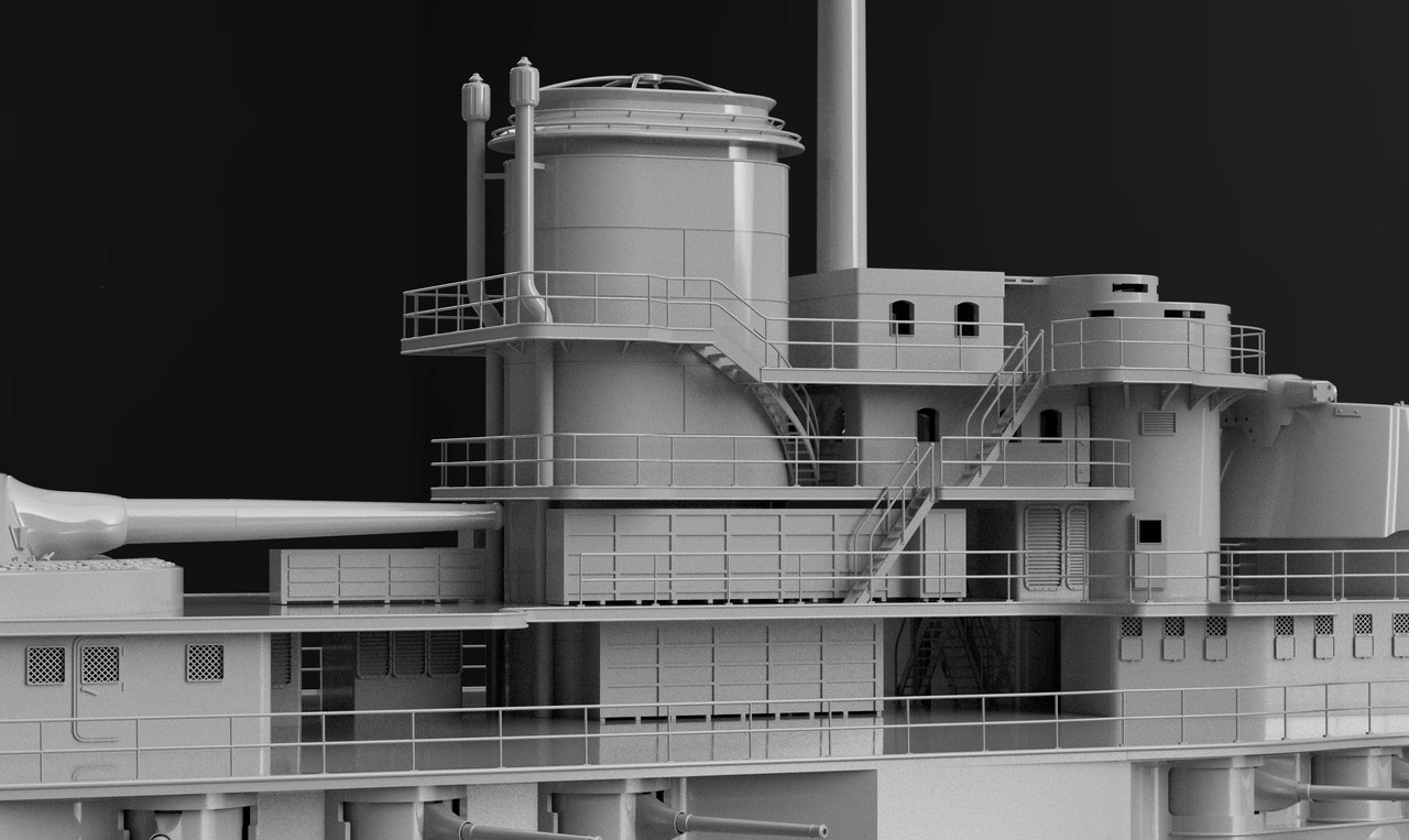
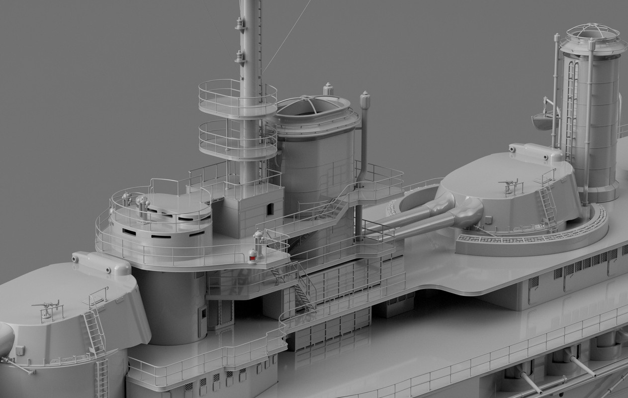
I almost completed the finishing of the fore stack.
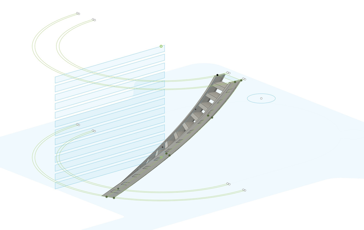
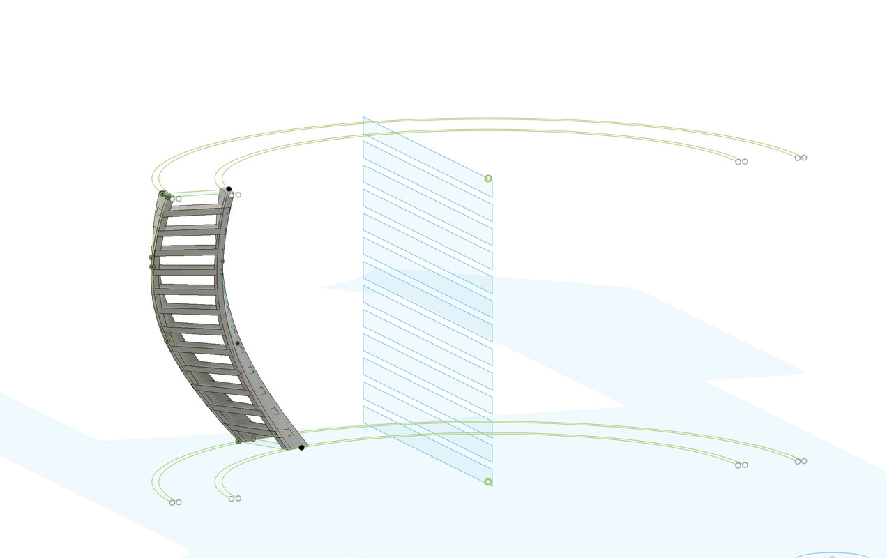
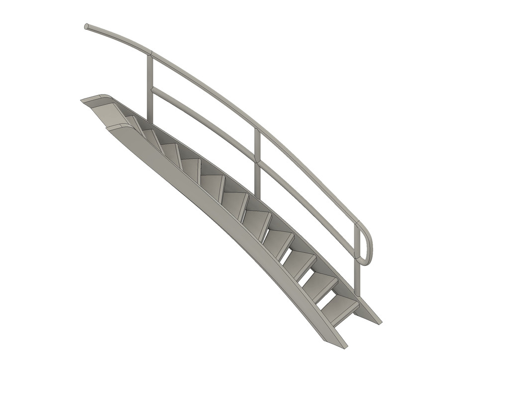
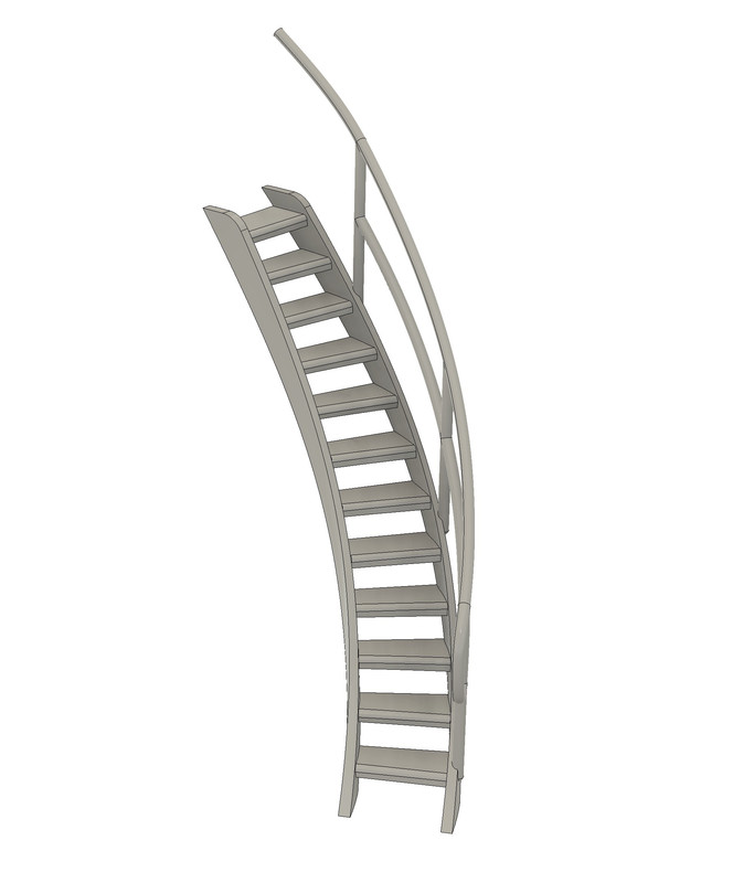
The difficult exercise was to draw the 2 spiral stairs in front of the stack.
But it's not too bad for a first. Two good hours of drawing and finding the right method.
Joined: Sun Mar 07, 2010 12:01 am Posts: 1677 Location: Corvallis, Oregon, USA
Pascal,
Nice work on the spiral ladders. Spirals are tricky to produce in CAD, and even harder to fabricate in scale. This is where 3D printing really comes in handy!
****
In the 1700s the crew's hammocks were stowed in hammock nets along the tops of bulwarks on the sides of ships. In the 1800s the nets were replaced with wooden boxes. They were there to catch shrapnel and musket fire.
I know it was standard practice to bundle bedding around bridge railings in the Japanese Navy. They had them on the Mikasa (early 1900s) in Yokosuka Japan when I was there, and they used them on their carriers in WWII (as shown in your photo).
I thought the things in the bridge bunker on the Bretagne look something like hammocks, but the location seems strange. They seem to be "protecting" a heavily armored turret!
_________________ A collision at sea will ruin your entire day. Aristotle
When I first saw the cellular structure, I actually thought that it might me there to protect the base of the turret by making any shells with impact fuse detonate before they actually hit and potentially penetrate the base - like the add-on armour on tanks during WW2.
_________________ Eberhard
Former chairman Arbeitskreis historischer Schiffbau e.V. (German Association for Shipbuilding History)
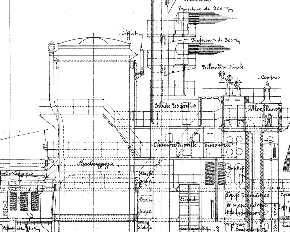
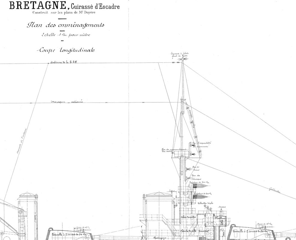
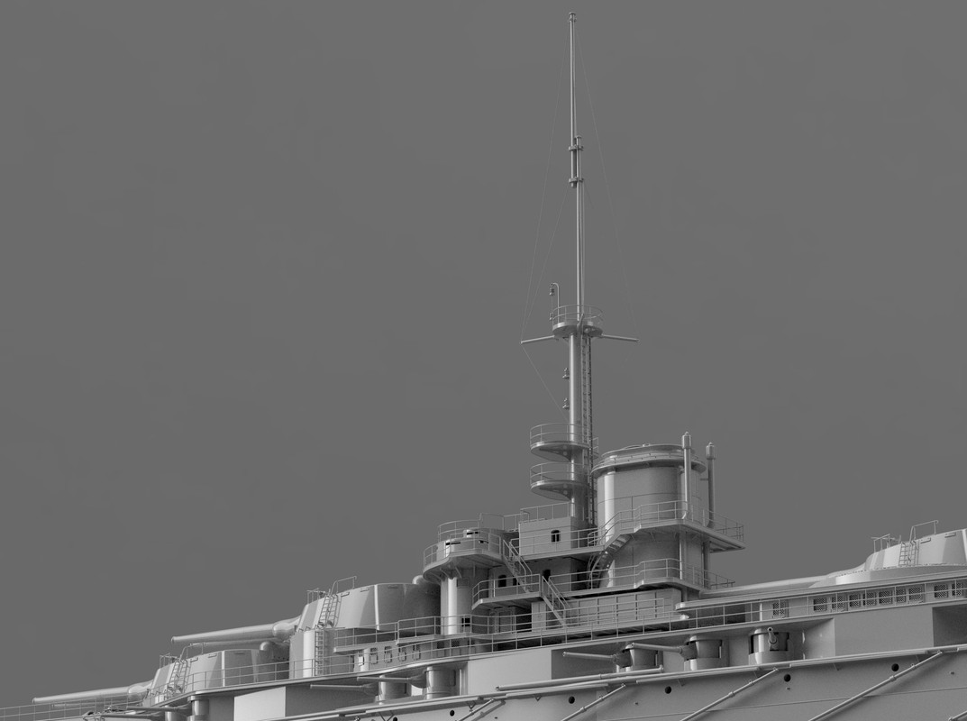
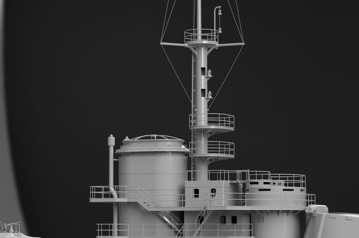
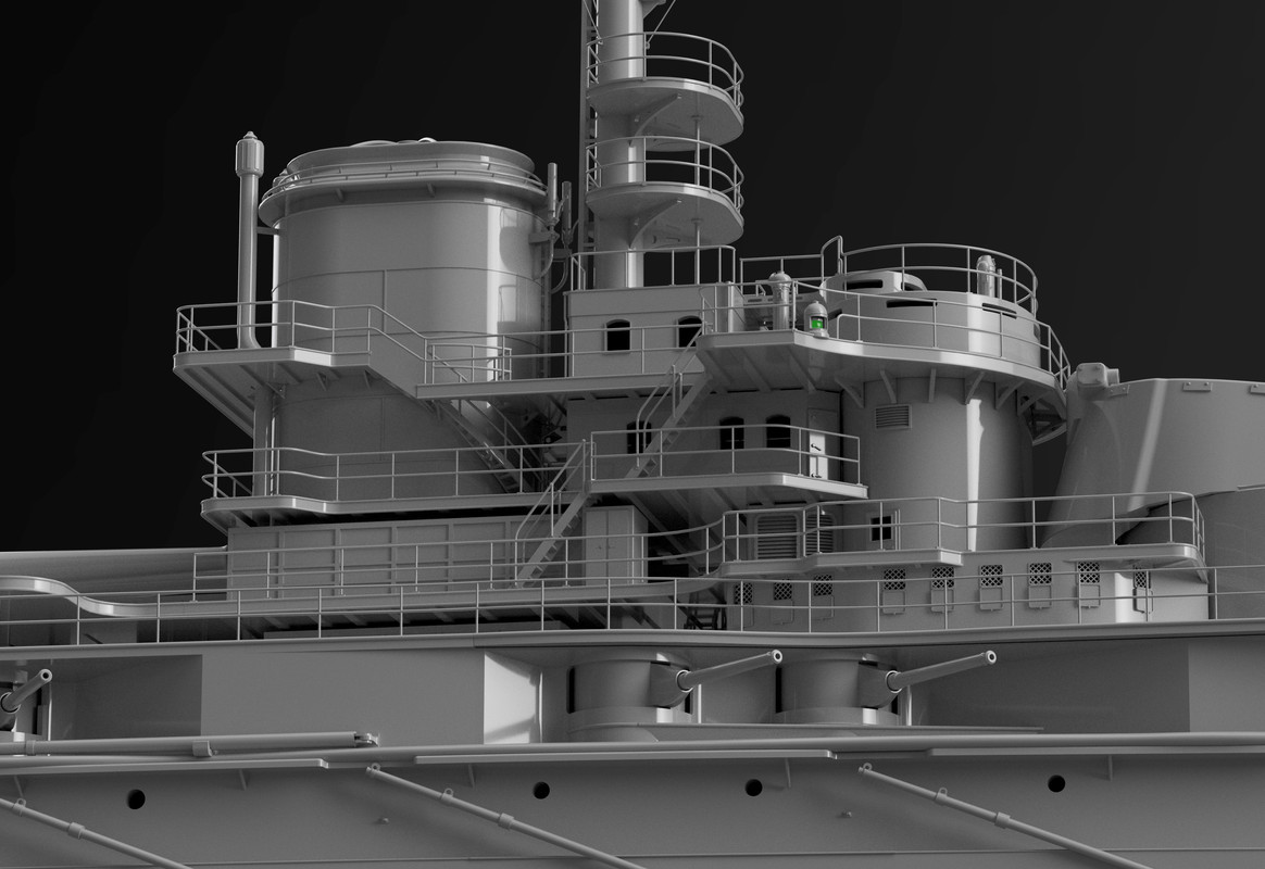
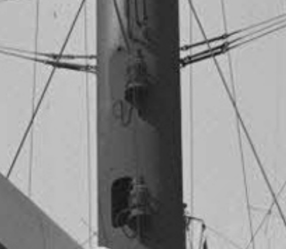
I have been working on the front mast mainly, these last few days.
There are two accesses to the navigation lights to service them in the middle of the main mast, the mast is hollow, access is by climbing down an inside ladder from the crow's nest.
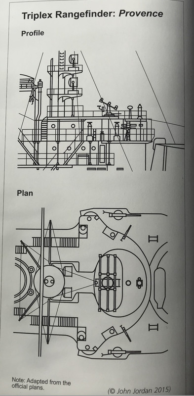
If anyone has pictures/plans of the triplex rangefinder and searchlights, I'm interested.
"The effectiveness of shipborne artillery is not just about the size of the guns. It is a question of aiming quickly and well. To do this, the "fire control" is developed, which some will go so far as to present as a science. (Examples will be taken from the battle of Jutland).
The fire control is entrusted to an officer. To ensure the best visibility, he was installed high up, sometimes in the mast. An armored hune should allow him to observe, at a distance of several tens of kilometers, in spite of the smoke of the guns, the curtains of smoke, the sheaves of fire, targets moving at speeds of 40 to 50 km/h. And these targets are usually only visible through their own mast. At the level of the turrets, the adversary is then completely out of sight.
The fire control officer uses a rangefinder or rangefinders to determine distances. The British used coincidence rangefinders, the Germans stereoscopic rangefinders. It seems that the latter were more accurate. In addition to the officer, there are several sailors in the gun emplacement, each performing a specific task. For example, to continuously adjust a rangefinder, or to receive orders from the commander.
The gunnery officer was forced to concentrate so hard that he was unaware of what was going on around him. For example, it took a British gunner several hours to realize that two of the six ships in his division had sunk.
The indications of the firing officer were transmitted to the calculation station, a sheltered area at the bottom of the ship. There, the two elements essential to the turrets were calculated, the elevation (pointing at the height of the guns) and the bearing (pointing in the direction of the guns). To determine these parameters, the distance to the target, its course, its relative speed, but also the wind, the hygrometry, the duration of the projectile's journey, the latitude (for the calculation of the Coriolis force), and even the quality of the powder are taken into account. Remember that there are no computers and the calculations are done by hand.
The result of the calculations is transmitted to the turrets and sent back to the firing officer for observation of the results. There is no remote control. In the turrets, the elevation and bearing calculated by the central calculation station are displayed and their indications are repeated by the sailors by operating the adjustment wheels. Remember that, in their closed turret, the sailors do not know what they are shooting at.
Transmission errors are inevitable with such a procedure. The gunnery officer of the Derfflinger will tell us that his firing corrections transmitted to the computer station seemed to have no effect. He multiplied by two the transmitted data and had then the satisfaction to see the sheaves framing his goal.
The firing is triggered by the firing officer. It is common for the guns to fire successively and not together, on the one hand to spare the ship's structure, and on the other hand to appreciate more easily the result of the firing. There are two types of firing: the "adjustment firing" and the "efficiency firing". The first makes it possible to determine the correct firing parameters. To do this, the firing officer monitors the arrival of the shells he has just launched. To help him, clocks are set to the expected flight time. They then rang, as much to awaken the attention of the sailors as to allow them to distinguish the sheaves of fire from the other ships.
Depending on the results observed, the firing officer will make "jumps" in bearing and distance. When the sheaves surround the target, he will trigger the "efficiency shot", where all the guns will fire as quickly as possible. He can also choose the type of shell. The ships of the line of the time carried "explosive shells", which exploded on contact, and "rupture shells", which had to penetrate the armour before exploding. The efficiency of the latter decreases with the range. It was three such shells, sent by SMS Von der Tann, that sank the HMS Indefatigable.
Joined: Sun Mar 07, 2010 12:01 am Posts: 1677 Location: Corvallis, Oregon, USA
Pascal,
There were two other considerations with the gunfire at Jutland.
Each German ship carried projectiles loaded with colored dye (the Japanese also used this at Battle of Tsushima). This allowed each ship to discern which splashes were from its shells. The dye was carried in a thin aerodynamic shell over the blunt end of the shell's armored casing.
A reason for firing guns in a turret successively, rather than all at once, is that the blast from neighboring guns fired simultaneously deflects the projectiles, reducing accuracy. This was especially noticeable in turrets having guns spaced closely together. The delay between successive shots can be very short, making it look as if all guns fired at the same time. But photos that capture the shells leaving the guns show that they are flying one after the other.
A potential problem with successive firing guns is that guns that are not on the centerline of the turret generate torque to rotate the turret. There is always a bit of play in the turret rotation mechanism that allows it to rotate slightly, changing the aim of guns that have not yet fired. One solution to this on three gun turrets was to fire the center gun first while the turret was aimed directly at the target, and then fire the two outboard guns simultaneously to apply equal rotational torque in each direction. These guns were widely spaced and the blast effect deflecting the projectiles was not so pronounced. With muzzle velocities greater than the speed of sound these outboard projectiles might escape the blast effect from other guns completely.
These were lessons that were being learned in the early 1900s. Some navies used successive firing but others did not.
Phil
_________________ A collision at sea will ruin your entire day. Aristotle
The Japanese persisted in using dyed shells even at Leyte (off Samar), one of the few daytime engagements. Many of the post war Cruisers and Battleships (USN) used rifles elevated in a single sleeve. Adoption of wider spaced barrels and individual sleeving for elevation as well as timing of the discharge helped reduce dispersion. For shore bombardment air spotting of shell fall was common, owing to local air superiority. More often, in USN practice shell spotting was done via radar ranging on the splashes.
Bretagne spanned an interesting era of unparalleled development of the big gun navies. What naval warfare would have been like without the development of those pesky airplanes?
Joined: Sun Mar 07, 2010 12:01 am Posts: 1677 Location: Corvallis, Oregon, USA
The US Navy still carried rounds with dye markers after WWII. I think they were still in the ordnance list during Vietnam but I don't recall that we actually had any. We were mostly shooting at bushes in the jungle so we couldn't see the dye even if it was there.
I posted information about the 6"/47 and 5"/38 guns and ammunition here:
I am guessing that most post war rounds in inventory were war production. I do recall that Bangor Ammunition Depot during the mid 60's still had many thousands of 16" shells in their stocks, though they did dispose of a lot of old bag powder (via burning). Post war different powders with better properties became available, leading to extended barrel life. Reduced charges when max velocity wasn't needed for max range of armor penetration also helped deal with barrel erosion.
Examination of shore installations on Tarawa after the invasion indicated that the bunkers more likely needed use of armor piercing shells for deeper penetration, as well as selective targeting as opposed to area bombardment. Later experiments were conducted on Kahoolawe as to best implementation.
Bretagne, place in service only 40 short years after the American Civil War was light years of change from that era. She began a short but important era of naval construction!
I spent a lot of time searching for documents on internet and books.
The progress of the day, minimal at the sight, but I modified a lot of things that were not good before continuing further in the drawing, like shortening the front stack that was a bit long, not easy at this level of advancement of the drawing because of the overlapping of the different decks around...
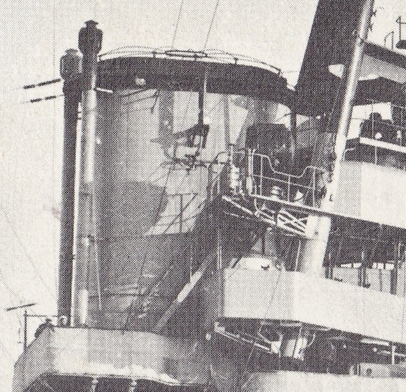
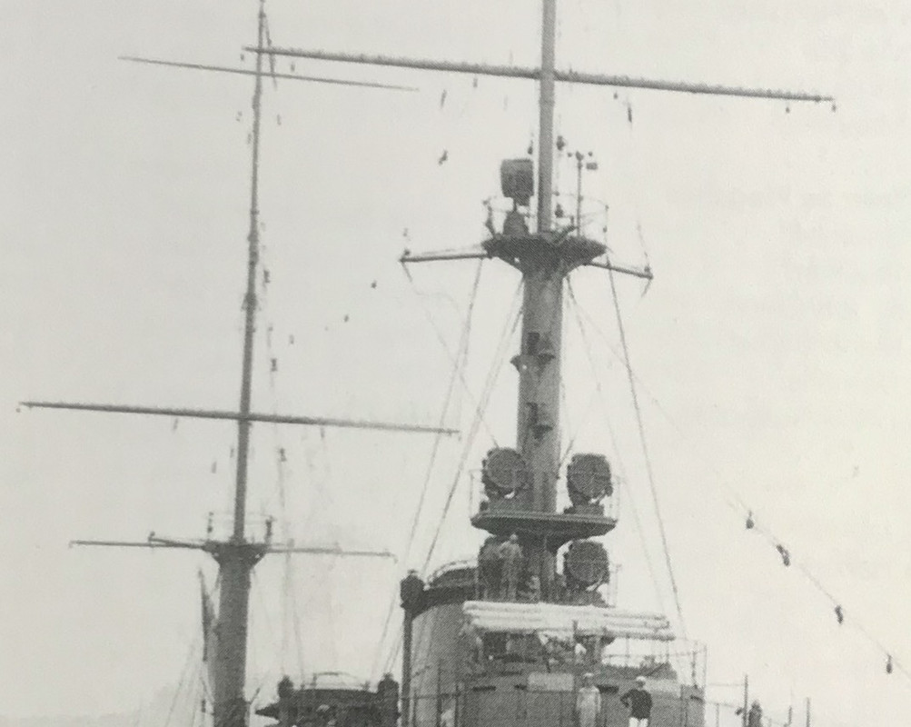
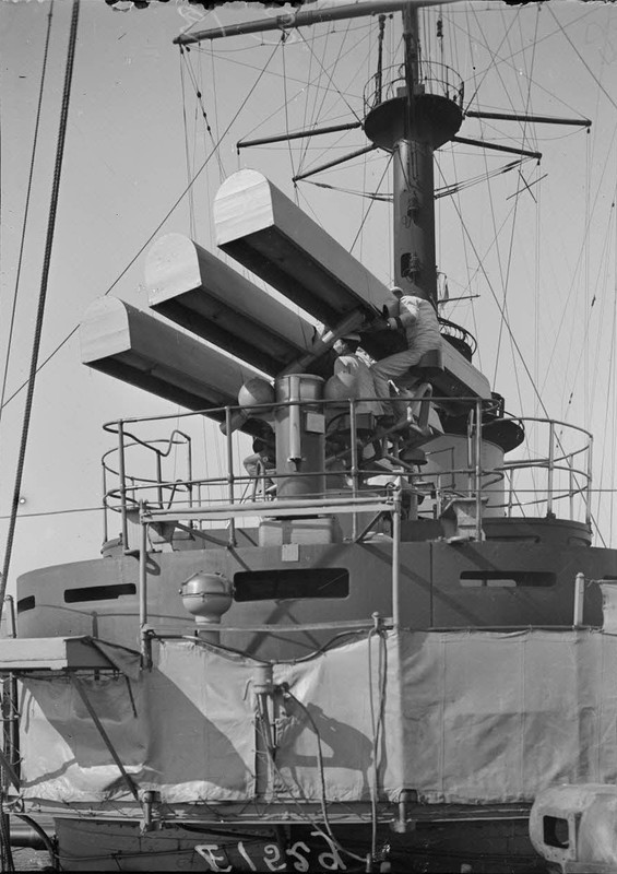
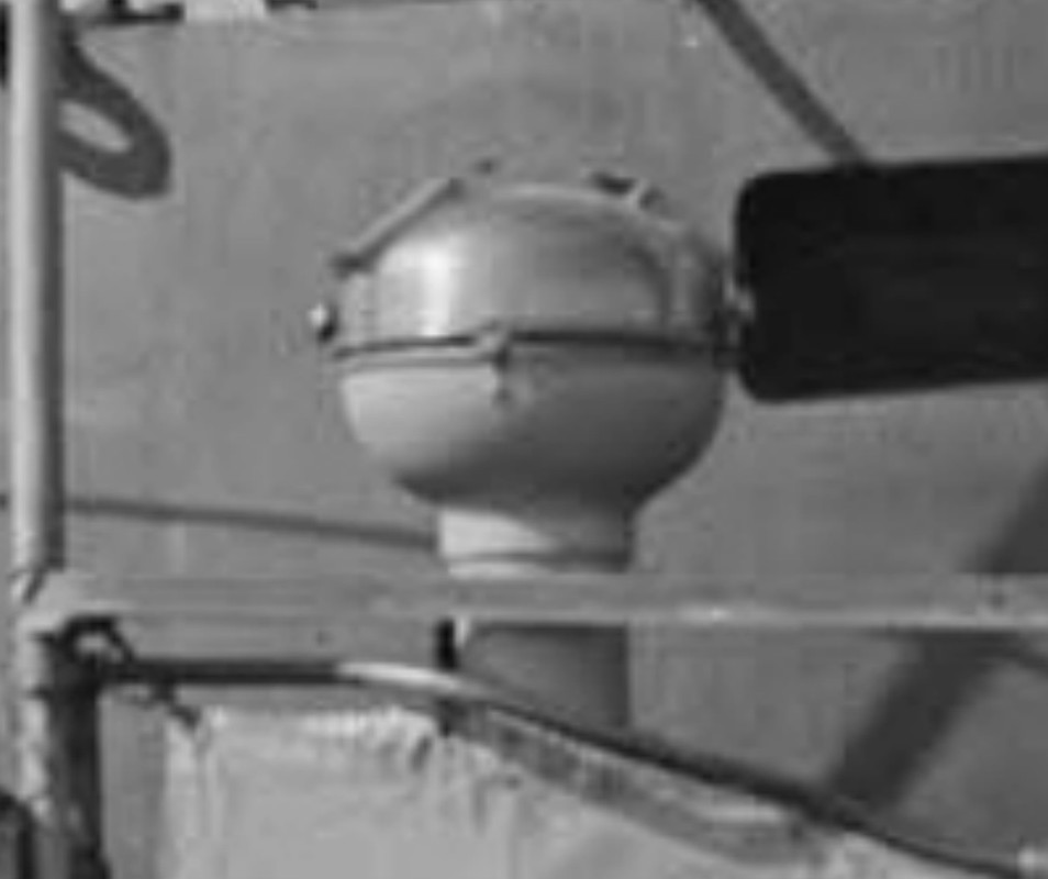
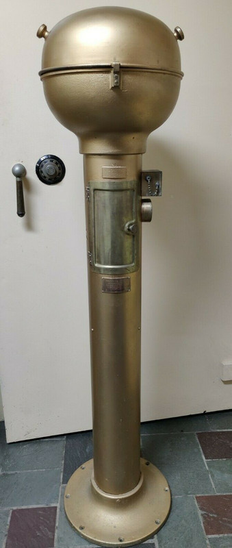
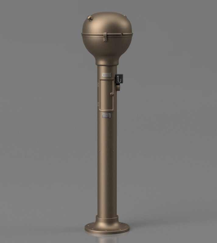
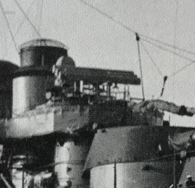
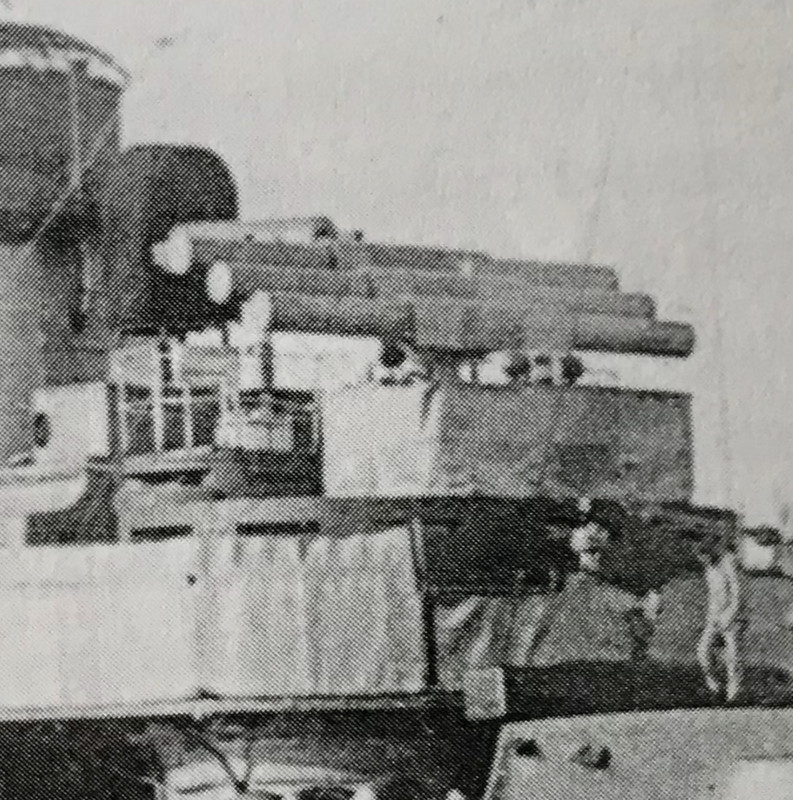
I think I found the rare pearl for the Triplex rangefinder, there are plenty of details on the blockhouse as well, including another American Pelorus style compass that I already designed for the Nokomis tug.
It would be 3 FT24 tubes of 15 feet long ( there is an error in the book which speaks of FT23, it does not exist in 15).
I found the picture on Reddit, it's the only place where this picture is posted on the net, so I don't have the origin of the picture.
Too bad the main compass hides the mount. And that the sun visor covers are in place. For the foot, the plan will help me.
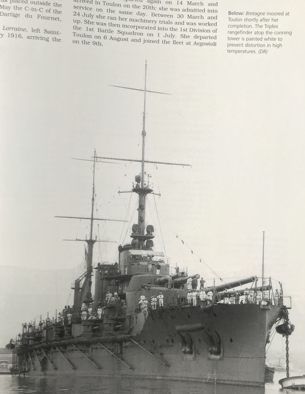
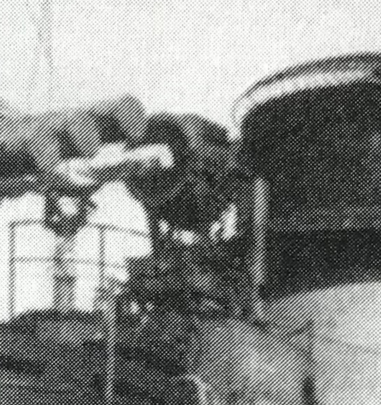
The rangefinder tubes were painted white to avoid any deformation with the heat of the sun which can affect the accuracy. On a picture below, we see a canvas sunshade.
"Barr and Stroud triple rangefinder used by French ships during WWI. One rangefinder measured distance to target, the second measured distance to shell bursts to obtain a "range error", and the third was used to correct the first two by alternating measurements."
Italy:
"In 1917, the RM purchased seven FT25 "Triplex" rangefinders from Barr & Stroud, which were used to equip the five surviving dreadnought battleships (the Leonardo da Vinci having already been sunk), replacing the original forward rangefinder turret they had (which was equipped with a 9-foot Barr & Stroud rangefinder or a 3-meter Zeiss); the aft turret, with the corresponding rangefinder, was retained.
The inability to acquire modern rangefinders in a timely manner (because, with the increasing distance to Germany, Zeisses were no longer available, and British ones could only be acquired after RN requests were fulfilled) highlighted the inability of Italian industry not only to provide competitive optical equipment for its capital ships, but also the absence of any company or factory, public or private, capable of building even small rangefinders. Attempts to build them during the war had to start from scratch, and what was built was virtually unusable."
Note the main compass on the blockhouse, the binocular row on the Brittany and the 47mm gun mount on the turret.
FT24 of 9 or 15 feet ( 15 feet for what concerns us, that is to say tubes of 4,57 mt long :
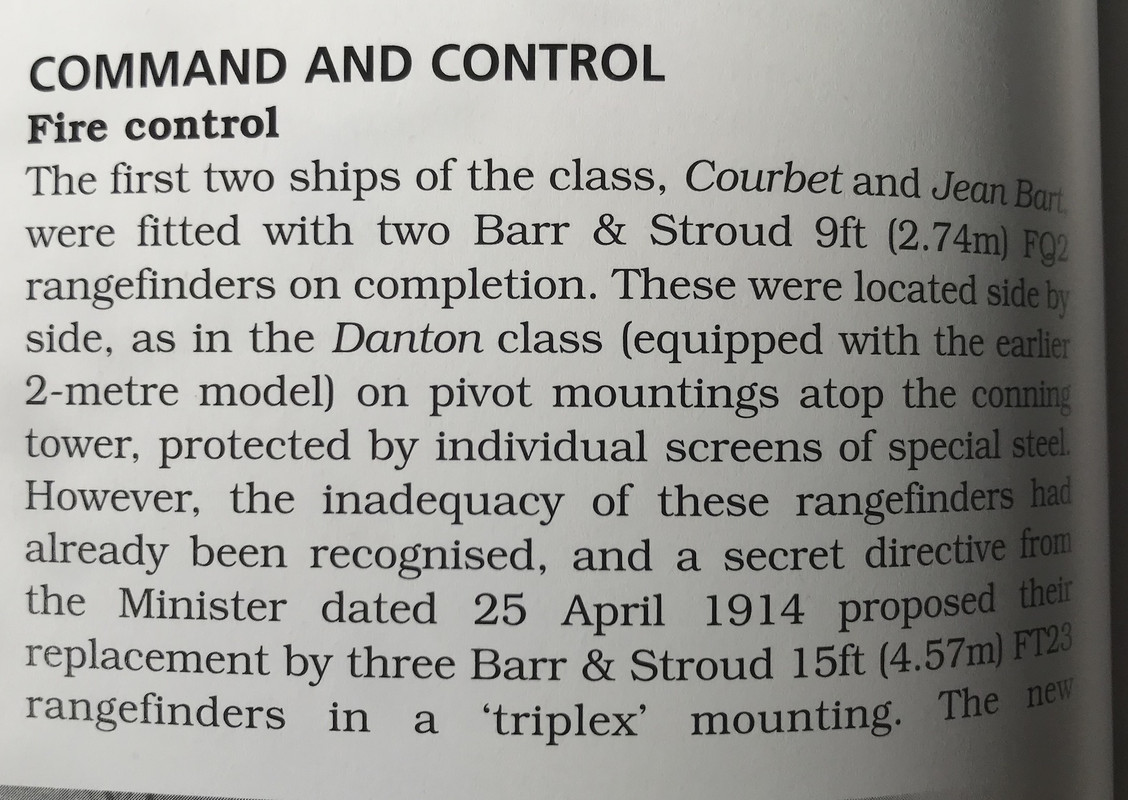
"Fire control:
The first two ships of the class, Courbet and Jean Bart were equipped with two Barr & Stroud 9-foot (2.74 m) FQ2 rangefinders at the end. These were located side by side, as in the Danton class (equipped with the earlier 2-meter model) on swivel mounts atop the turret, protected by individual special steel screens.
However, the inadequacy of these rangefinders had already been recognized, and a secret directive from the Minister dated 25 April 1914 proposed their replacement by three Barr & Stroud 15-foot (4.57 m) [strike]FT23[/strike] FT24 'triplex' mountings. The new...."
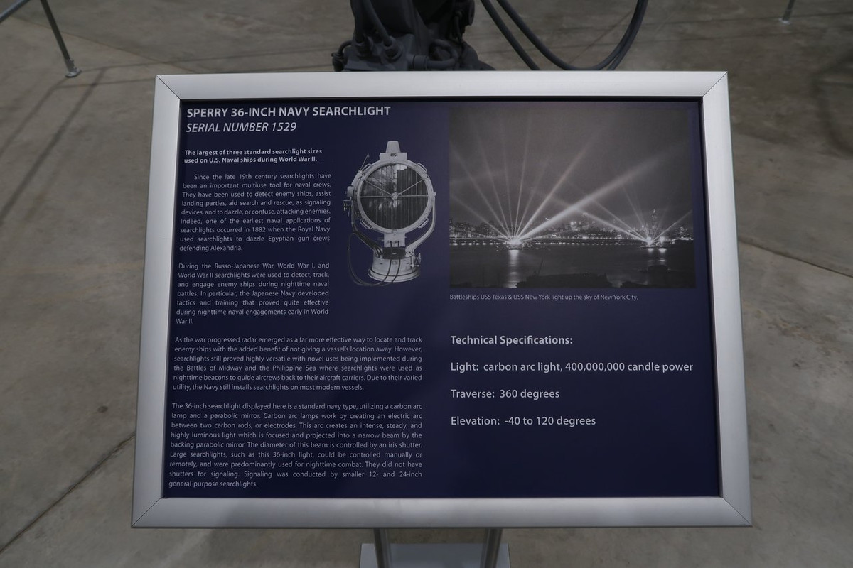
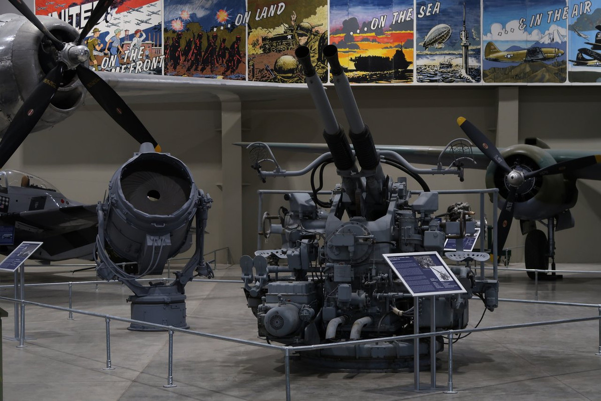
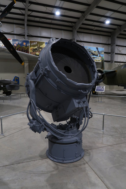
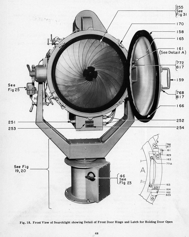
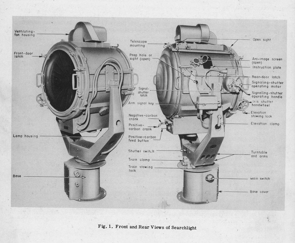
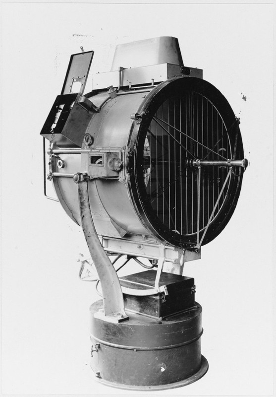
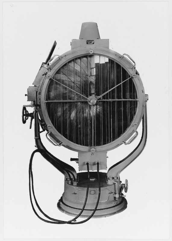
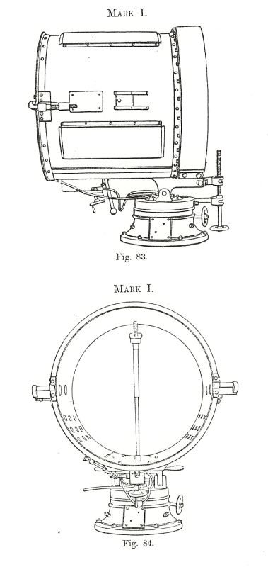
Note that the serachlight installed would probably be from the well known brand Sperry.
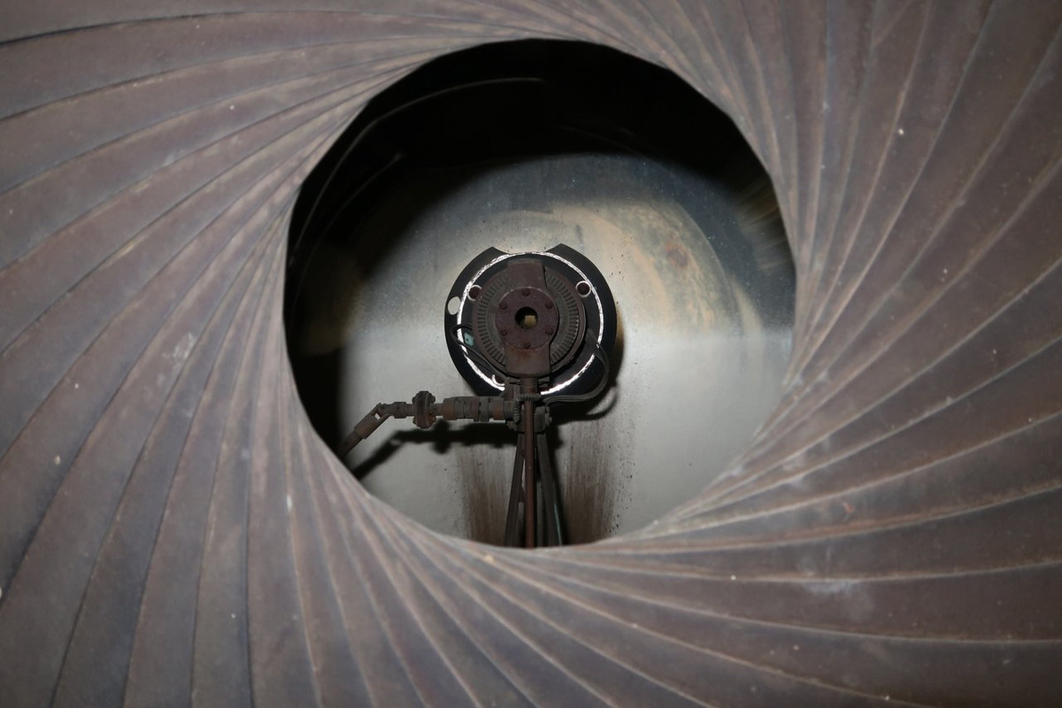
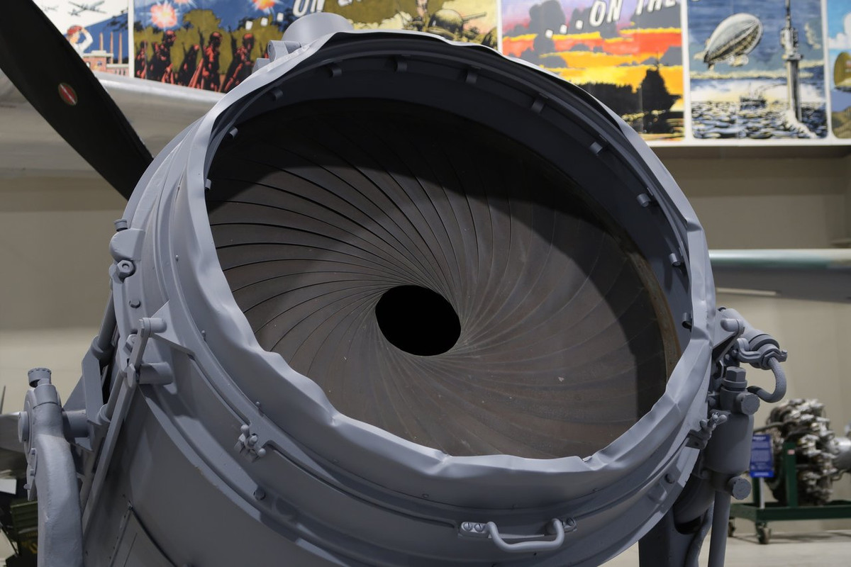
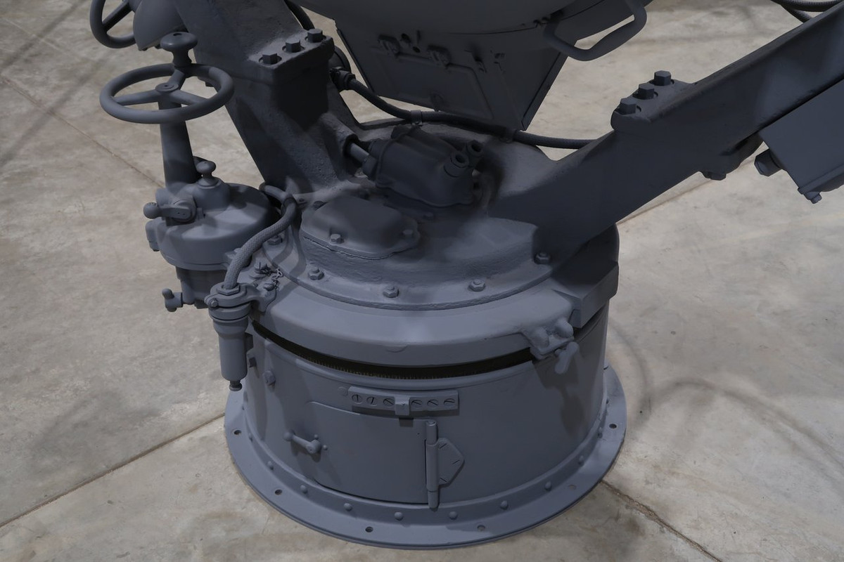
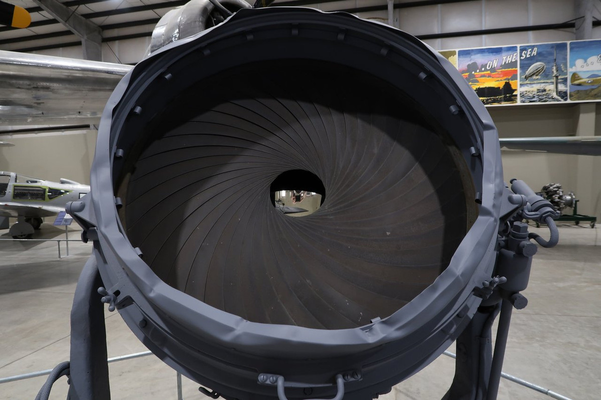
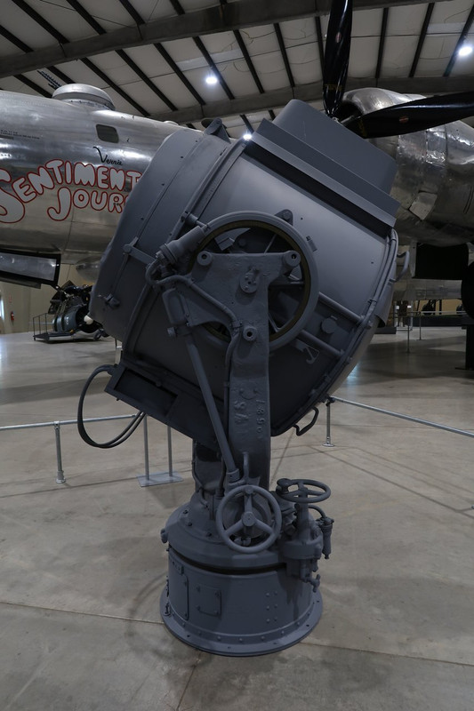
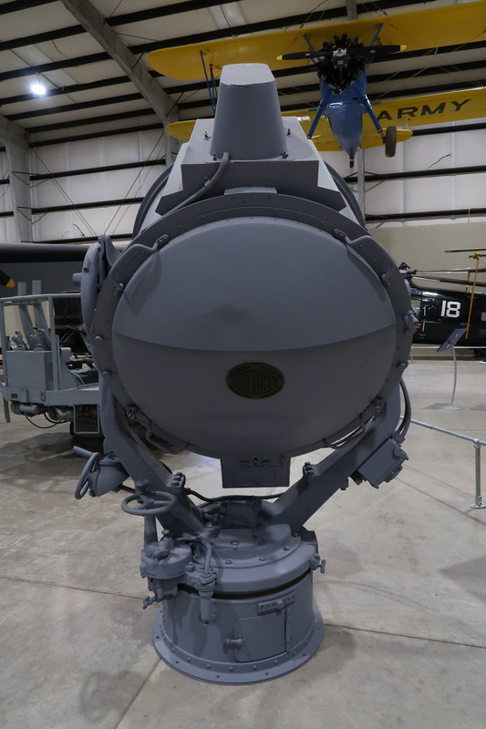
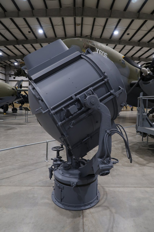
Sperry 36-inch Navy Searchlight
Pima Air and Space Museum
SPERRY 36-INCH 90 cm NAVY SEARCHLIGHT SERIAL NUMBER 1529
The largest of the three standard searchlight sizes used on US Navy ships during World War II.
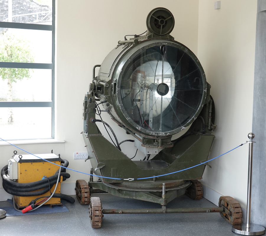
Since the late 19th century, searchlights have been an important multipurpose tool for naval crews. They have been used to detect enemy ships, assist landing parties, aid in search and rescue, as signaling devices and to dazzle or confuse attacking enemies. Indeed, one of the first naval applications of searchlights occurred in 1882, when the Royal Navy used searchlights to dazzle Egyptian gun crews defending Alexandria.
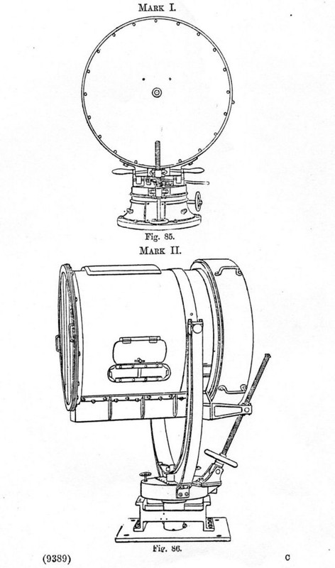
During the Russo-Japanese War, World War I and World War II, searchlights were used to detect, track and engage enemy ships during night naval battles. The Japanese Navy, in particular, developed tactics and training that proved highly effective in nighttime naval engagements early in World War II.
As the war progressed, radar emerged as a far more effective means of locating and tracking enemy ships, with the added benefit of not revealing a ship's location. However, searchlights proved to be very versatile and were first used in the battles of Midway and the Philippine Sea, where they served as night beacons to guide crews to their carriers. Because of their varied utility, the Navy still installs searchlights on most modern ships.
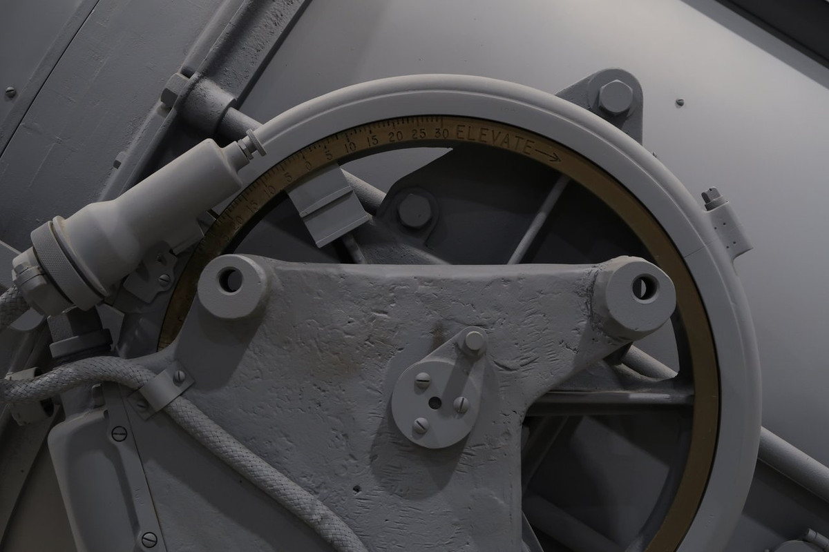
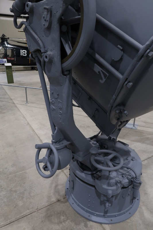
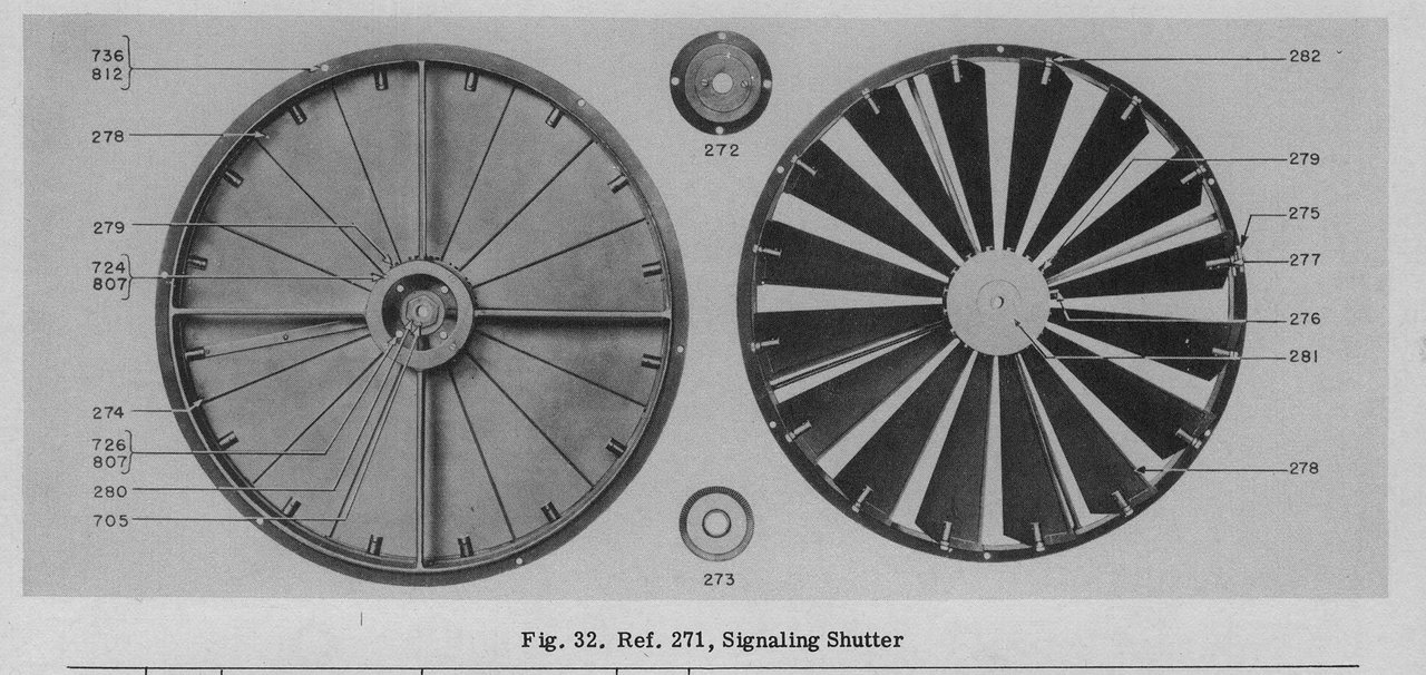
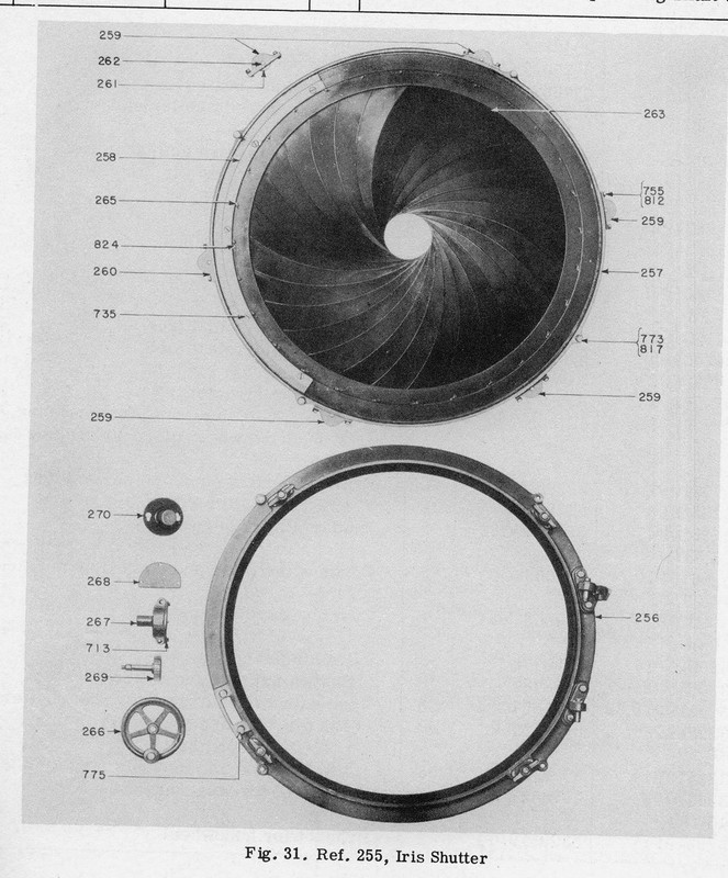
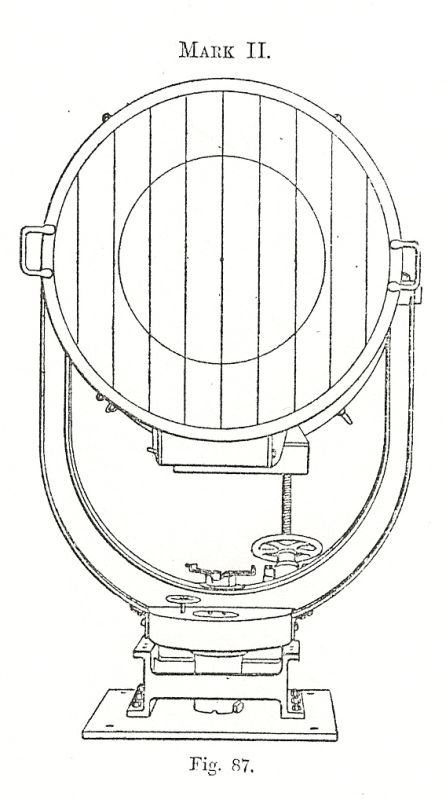
The 36-inch searchlight shown here is a standard Navy model, using a carbon arc lamp and a parabolic mirror. Carbon arc lamps work by creating an electric arc between two carbon rods, or electrodes. This arc creates an intense, constant and very bright light that is focused and projected in a narrow beam by the rear parabolic mirror. The diameter of this beam is controlled by an iris shutter. Large searchlights, such as this 36-inch searchlight, could be controlled manually or remotely, and were primarily used for night fighting. They did not have a shutter for signaling. Signaling was provided by smaller 12 and 24 inch general purpose searchlights.
Technical specifications
Light: carbon arc lamp, power of 400 000 000 candles
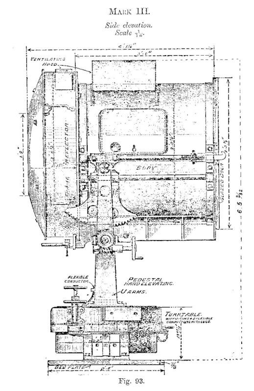
Thank you for the photos and data on the USN 36" searchlight. Despite her advanced fire control, Alaska carried four of these. I have always though that manning a searchlight in a night combat must have been daunting, completely exposed and the point of interest!
Users browsing this forum: No registered users and 38 guests
You can post new topics in this forum You can reply to topics in this forum You cannot edit your posts in this forum You cannot delete your posts in this forum You cannot post attachments in this forum