The Ship Model Forum

The Ship Modelers Source
It is currently Sat Jul 12, 2025 4:18 pm

All times are UTC - 6 hours [ DST ]


Post new topic Reply to topic  [ 171 posts ]  Go to page Previous  1, 2, 3, 4, 5 ... 9  Next
Author Message
PostPosted: Fri Oct 02, 2020 7:53 pm 
Offline

Joined: Wed Jan 02, 2013 1:15 am
Posts: 5060
Interesting detail with the prop fairing contained on the leading edge. This is a very similar stern/prop/rudder to the C2-C3 ships. This unless constructed very carefully would tend to impinge on the prop hub with port or seaboard rudder activation. Just something I haven't see before!

I can see why the tankers had a lot of deck camber, at times they looked like semi submersibles.


Report this post
Top
 Profile  
Reply with quote  
PostPosted: Sat Oct 03, 2020 4:00 am 
Offline
User avatar

Joined: Tue Sep 29, 2020 4:35 pm
Posts: 1881
Location: Bretagne, France
DavidP wrote:
is this model for radio control use?


No David, static purpose. ;) Too fragile.

_________________
Pascal

•Battleship Bretagne 3D: https://vu.fr/FvCY
•SS Delphine 3D: https://vu.fr/NeuO
•SS Nomadic 3D: https://vu.fr/tAyL
•USS Nokomis 3D: https://vu.fr/kntC
•USS Pamanset 3D: https://vu.fr/jXGQ


Report this post
Top
 Profile  
Reply with quote  
PostPosted: Sat Oct 03, 2020 5:37 am 
Offline
User avatar

Joined: Tue Sep 29, 2020 4:35 pm
Posts: 1881
Location: Bretagne, France
I took care of the propeller yesterday, 20 july , a new exercise that can be a bit daunting.


I tried a tutorial found on youtube for Fusion 360, but I didn't like the result, a tutorial rather suitable for a schematic outboard propeller, the method was not suitable for a large ship propeller, much more complex in terms of shapes, the profile of the blade.


So I racked my brain using a method I know as an aeromodeller, I created a blade like an airplane wing, it's very similar to it, with ribs, then I twisted it once the structure was finished, then filled it with one of the very powerful functions of the program, delicate to use when the shapes are complex. Sometimes you have to do it over and over again.

First of all some captures made last night after the rudder was finished;

Image

Image

Image

Image

I prepared the impression of two rudders, I knew that there would be a long hole to make for the rudder needle, easy to miss, this axis will be made of piano wire, so it will be mobile.

Image

Then I started drawing the propeller with a second method mixing youtube tuto and the personal to give a profile to the blade, but it was not conclusive, no finesse at the end of the blade forms, except by tinkering for hours, I gave up, it was not the right method, we wipe the slate and start again ...

Image

Image

The result, not convincing to me. Go to the trash can!

Image

Then I used a radically different method. The idea worked well!

Image

Image

Image

Image

Image

Image

The holes are used to measure the vertical play of the propeller shaft in dry dock, there are plugs that have to be removed, a measuring tool like a calliper is inserted in them, and compared with the measurements made at new and at previous technical stops, a metal plate is in the tool box, it is punched with the different measurements each time. These measurements allow to know the condition of the shaft line bearings, it is done under supervision of the classification society, like Bureau Veritas or others.

The printed rudder.

Image

Image

It was also a test for a new resin (Elegoo), because it's difficult to get grey resin at Anycubic and the prices go crazy, I didn't see the difference, except that it smells even less... The price is very competitive compared to Anycubic. So I'm going to adopt it.

https://www.amazon.fr/ELEGOO-R%C3%A9sin ... ial&sr=1-4

Image

Starboard stern print. I can see the end of the hull adventure ..

Port side here in preparation.

Image

Raw casting, before a thorough sanding like the other elements, with water, 320 then 1000. This new resin has a different aspect from the other one, a rougher hair but as it will be sanded it doesn't matter.

Image

Image

1/4 hour sanding. This Elegoo resin is more suitable for sanding, really pleasant.

Image

I'm waiting until the half stern printout is done, 10 hours, prepare to print the propeller.

Image

Image

Image

Rare picture of the stern of a T2

Image

_________________
Pascal

•Battleship Bretagne 3D: https://vu.fr/FvCY
•SS Delphine 3D: https://vu.fr/NeuO
•SS Nomadic 3D: https://vu.fr/tAyL
•USS Nokomis 3D: https://vu.fr/kntC
•USS Pamanset 3D: https://vu.fr/jXGQ


Report this post
Top
 Profile  
Reply with quote  
PostPosted: Sat Oct 03, 2020 7:09 am 
Offline

Joined: Wed Jan 02, 2013 1:15 am
Posts: 5060
Will be very interesting to see how your prop comes out. I have flailed away at building one from brass and am not happy with the one that I have on the ship at the moment and will get around to working on that again.

For years I did flight dynamics for Flight simulator and worked with very talented 3D illustrators to create virtual aircraft. Thanks for the insights into your working methods!

Cheers: Tom


Report this post
Top
 Profile  
Reply with quote  
PostPosted: Sat Oct 03, 2020 7:28 am 
Offline
User avatar

Joined: Tue Sep 29, 2020 4:35 pm
Posts: 1881
Location: Bretagne, France
Tks Tom,

The blades propeller is not yet enough twisted on this model. For my next project, the propeller had to be more successful. :)

July 21:

The stern is glued. Which puts an end to this first season! ;)

I'm working on the drawing of the rear pump room in front of the rear castle.

Image

Image

Image

Image

Image

_________________
Pascal

•Battleship Bretagne 3D: https://vu.fr/FvCY
•SS Delphine 3D: https://vu.fr/NeuO
•SS Nomadic 3D: https://vu.fr/tAyL
•USS Nokomis 3D: https://vu.fr/kntC
•USS Pamanset 3D: https://vu.fr/jXGQ


Report this post
Top
 Profile  
Reply with quote  
PostPosted: Sat Oct 03, 2020 11:47 am 
Offline
User avatar

Joined: Tue Sep 29, 2020 4:35 pm
Posts: 1881
Location: Bretagne, France
July 23.

I'm working now on the aft pump room, and the masts version Pamanset.

Image

Image

Image

Image

Image

July 26.

I've been drawing a lot of things since yesterday, which take time, small details, masts, masts, pump rooms, and cargo tank domes.

I've drawn the sheet lines also on the hull, and the sketch lines of the Dazzle camouflage, different on port and starboard.

The masts were printed and came out rather well, the difficulty being the eyes for the fittings.

USS Mission Santa Ynez:

Image

Image

Image

Image

Image

Image

Image

Image

Image

Image

Image

Image

Image

Image

Image

Image

Image

_________________
Pascal

•Battleship Bretagne 3D: https://vu.fr/FvCY
•SS Delphine 3D: https://vu.fr/NeuO
•SS Nomadic 3D: https://vu.fr/tAyL
•USS Nokomis 3D: https://vu.fr/kntC
•USS Pamanset 3D: https://vu.fr/jXGQ


Report this post
Top
 Profile  
Reply with quote  
PostPosted: Sat Oct 03, 2020 1:02 pm 
Offline
User avatar

Joined: Tue Sep 29, 2020 4:35 pm
Posts: 1881
Location: Bretagne, France
They are at the same level.

Image

Image

Image

Image

_________________
Pascal

•Battleship Bretagne 3D: https://vu.fr/FvCY
•SS Delphine 3D: https://vu.fr/NeuO
•SS Nomadic 3D: https://vu.fr/tAyL
•USS Nokomis 3D: https://vu.fr/kntC
•USS Pamanset 3D: https://vu.fr/jXGQ


Report this post
Top
 Profile  
Reply with quote  
PostPosted: Sat Oct 03, 2020 1:43 pm 
Offline
User avatar

Joined: Tue Sep 29, 2020 4:35 pm
Posts: 1881
Location: Bretagne, France
I don't think so... The aft accommodation are not in place yet.

Image

Image

_________________
Pascal

•Battleship Bretagne 3D: https://vu.fr/FvCY
•SS Delphine 3D: https://vu.fr/NeuO
•SS Nomadic 3D: https://vu.fr/tAyL
•USS Nokomis 3D: https://vu.fr/kntC
•USS Pamanset 3D: https://vu.fr/jXGQ


Report this post
Top
 Profile  
Reply with quote  
PostPosted: Sat Oct 03, 2020 2:27 pm 
Offline
User avatar

Joined: Tue Sep 29, 2020 4:35 pm
Posts: 1881
Location: Bretagne, France
The plan:

Image

Image

_________________
Pascal

•Battleship Bretagne 3D: https://vu.fr/FvCY
•SS Delphine 3D: https://vu.fr/NeuO
•SS Nomadic 3D: https://vu.fr/tAyL
•USS Nokomis 3D: https://vu.fr/kntC
•USS Pamanset 3D: https://vu.fr/jXGQ


Report this post
Top
 Profile  
Reply with quote  
PostPosted: Sun Oct 04, 2020 1:52 am 
Offline
User avatar

Joined: Sun Mar 07, 2010 12:01 am
Posts: 1677
Location: Corvallis, Oregon, USA
Propellers are tricky. Most ships by the time of WWII had proportional pitch propellers. The angle of the blade along the blade axis rotates as the distance from the prop shaft axis increases. So the blade is twisted around the blade axis. The idea was to get roughly equal forces pushing on the water all along the length of the blade. Since the velocity of the blade through the water increases from the center outward the force imparted on the water at a given angle increases as the radius increases.

To equalize the forces the angle is varied to impart more or less the same force on the water (and, therefore, on the blade) at all radii. The angle relative to the motion through the water is greatest closest to the propeller hub and decreases outward. It's pretty tricky to model! Add to that the curvature where the blade meets the hub and you get very complex curved surfaces.

I have attached an image of a CAD model of the propeller for Cleveland class cruisers. It shows the twist of the blades. There are several other images of the propeller at different angles here:

https://www.okieboat.com/CAD%20miscellaneous.html

Scroll down to near the bottom of the page.

Phil


Attachments:
Propeller 1 1024 C.jpg
Propeller 1 1024 C.jpg [ 147.85 KiB | Viewed 1402 times ]

_________________
A collision at sea will ruin your entire day. Aristotle
Report this post
Top
 Profile  
Reply with quote  
PostPosted: Sun Oct 04, 2020 2:03 am 
Offline

Joined: Wed Jan 02, 2013 1:15 am
Posts: 5060
Thanks Phil:

Somewhere I have an APA prop photo, sitting on the dock and one can see clearly the change of pitch change along the blade length. Aircraft propellers have the same characteristics to attempt to keep the advance ratio constant. The tanker and the C-2/3 hulls are similar in many ways, but the transports have a stern post to which the rudder is attached, a different setup.

Modern propellers, as with jet turbine blades are examples of the limits of modern technology. Current submarine propellers are hidden from view for good reason.

Cheers: Tom


Report this post
Top
 Profile  
Reply with quote  
PostPosted: Sun Oct 04, 2020 10:39 am 
Offline
User avatar

Joined: Tue Sep 29, 2020 4:35 pm
Posts: 1881
Location: Bretagne, France
I took off the masts. With the platform configuration. The mule void of the aft masts is necessarily placed higher and turned outward by 15°. I'll have to modify in any case and re-print, the two at the back of forward castle are slightly smaller, it's visible on some photos of the Pamanset...

The famous platform used for refuelling and stores:

Here we can see a type of platform, this picture I just found will help me a lot, we can see the lifting winches that I will have to reproduce.

I started drawing again and had time to print my 4 new mats during this time.

I made a sketch of the platform, now I just have to put these mounts on it. The supports of the walkway are installed and adjusted in height. The DCA islands are drawn, their access gangways are still to be created, different at Psd and Stbd because of the main aft mast that comes in between. These flak islands are also equipped with a small vertical ladder, which allows the emergency evacuation of the island probably, they will be made of PE.

The aft cargo mast supports are designed to put the masts at the berth.
I only worked on photos for these new elements, no plan available.

I placed 4 Oerlikon 20 mm flak guns recovered for free on the internet.

Image

Image

Image

Image

Image

Image

_________________
Pascal

•Battleship Bretagne 3D: https://vu.fr/FvCY
•SS Delphine 3D: https://vu.fr/NeuO
•SS Nomadic 3D: https://vu.fr/tAyL
•USS Nokomis 3D: https://vu.fr/kntC
•USS Pamanset 3D: https://vu.fr/jXGQ


Report this post
Top
 Profile  
Reply with quote  
PostPosted: Sun Oct 04, 2020 10:45 am 
Offline
User avatar

Joined: Tue Sep 29, 2020 4:35 pm
Posts: 1881
Location: Bretagne, France
<-- See next page

Work today on the middle slice. Drawings of the walkways of the flak islands, support of the refuelling platform.
Printing, then gluing the printed elements, some of them older. Gluing of the 4 new mats. The catwalks came out well, despite their finesse.
I recovered from the floor of the Bismarck bridge falls
I should have enough material for the refueling platform as well, this floor will be painted with this Dazzle Measure 32 3AO camouflage standard, probably Deck Blue 20-B or partly with Ocean Grey 5-O.

Image

Image

Image

Image

Image

Image

_________________
Pascal

•Battleship Bretagne 3D: https://vu.fr/FvCY
•SS Delphine 3D: https://vu.fr/NeuO
•SS Nomadic 3D: https://vu.fr/tAyL
•USS Nokomis 3D: https://vu.fr/kntC
•USS Pamanset 3D: https://vu.fr/jXGQ


Report this post
Top
 Profile  
Reply with quote  
PostPosted: Sun Oct 04, 2020 10:50 am 
Offline
User avatar

Joined: Tue Sep 29, 2020 4:35 pm
Posts: 1881
Location: Bretagne, France
I mounted some PE today for a change. From the Chinese one I bought for the Hornet CV-8 (30 Oerlikon, I was missing the 20 mm brass guns), I borrowed 4 of them for this tanker.

I reordered some, they come in sets of 8 with PE spares. The quality is not bad far from there. There is no resin, it's all brass. The charger is missing though.

Normally 20 mm. double mounts were mounted on this ship, but I'll skip, not find, other tankers had singles.

I still have the ammunition cases to make them in this style:
Image

Image

Image

Image

I'm looking for a 5" 38 barrel for the rear platform, not easy to find, I found a 5" 25.

Image

To sum up:

http://www.aukevisser.nl/t2tanker/id483.htm
Armament:
1 - 5"/38 dual purpose gun carriage.

5" 25 :
https://www.shapeways.com/product/4PBV4 ... -cm-aa-gun
Image

4 x 3"/50 cannons.

4 twin 40 mm cannons.

4 twin 20 mm barrels, which I replaced with singles.

I think some are missing, I counted 19 pieces on the picture at the bottom of the post about the USS Sebec...

There are probably a total of 12, 20 mm Oerlikons. Those ships were heavily armed.

Image

You can see the three ammunition box on each islet here:

Image

Image

Image

Image

The armament configuration of the USS Pamancet probably:
USNS Sebec (AO-87): Same class.
Image

I just noticed a detail in this photo, this type of ship was obviously equipped with a depth charge launcher . One more thing to add.

USS Ponaganset (AO-86), same class, this ship will break in two, later...

Image

Image

Image

Image

_________________
Pascal

•Battleship Bretagne 3D: https://vu.fr/FvCY
•SS Delphine 3D: https://vu.fr/NeuO
•SS Nomadic 3D: https://vu.fr/tAyL
•USS Nokomis 3D: https://vu.fr/kntC
•USS Pamanset 3D: https://vu.fr/jXGQ


Report this post
Top
 Profile  
Reply with quote  
PostPosted: Sun Oct 04, 2020 10:53 am 
Offline
User avatar

Joined: Tue Sep 29, 2020 4:35 pm
Posts: 1881
Location: Bretagne, France
Some progress in the last couple of days.
Designed and printed the entrance to the forward pump room. It's finished, paint 20 B, PE door open, hatch etc... I'm happy with the result.

I put some stairways, drew the mooring bitts, and printed it.

Printed and laid the central gangway of the bow section.

The aft section's AA islands are completely finished.

Received the railing from Tom's Modelworks, 2 rails type, I glued a piece on the forecastle, it looks good, it's extremely thin. It was 2 rails at the time, later replaced by 3 after the war.

Image

Image

Image

Image

Image

Image

Image

Image

Image

Image

Image

Image

Image

Image

_________________
Pascal

•Battleship Bretagne 3D: https://vu.fr/FvCY
•SS Delphine 3D: https://vu.fr/NeuO
•SS Nomadic 3D: https://vu.fr/tAyL
•USS Nokomis 3D: https://vu.fr/kntC
•USS Pamanset 3D: https://vu.fr/jXGQ


Report this post
Top
 Profile  
Reply with quote  
PostPosted: Sun Oct 04, 2020 12:28 pm 
Offline

Joined: Wed Jan 02, 2013 1:15 am
Posts: 5060
Interesting winch on the forward well deck with the winch power midships and a long shaft to catheads port and starboard. I can't imagine any practical employment for the stern K guns on a large poorly maneuverable ship?

Great progress! Cheers: Tom


Report this post
Top
 Profile  
Reply with quote  
PostPosted: Sun Oct 04, 2020 12:40 pm 
Offline

Joined: Wed Jan 02, 2013 1:15 am
Posts: 5060
This might be a simpler and more typical K gun, in this case as found on a Fletcher Class Destroyer.

Attachment:
K gun.jpg
K gun.jpg [ 162.93 KiB | Viewed 1302 times ]


Report this post
Top
 Profile  
Reply with quote  
PostPosted: Sun Oct 04, 2020 4:36 pm 
Offline
User avatar

Joined: Tue Sep 29, 2020 4:35 pm
Posts: 1881
Location: Bretagne, France
Thanks for the drawing, Tom.

_________________
Pascal

•Battleship Bretagne 3D: https://vu.fr/FvCY
•SS Delphine 3D: https://vu.fr/NeuO
•SS Nomadic 3D: https://vu.fr/tAyL
•USS Nokomis 3D: https://vu.fr/kntC
•USS Pamanset 3D: https://vu.fr/jXGQ


Report this post
Top
 Profile  
Reply with quote  
PostPosted: Mon Oct 05, 2020 10:03 am 
Offline
User avatar

Joined: Tue Sep 29, 2020 4:35 pm
Posts: 1881
Location: Bretagne, France
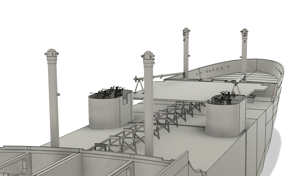
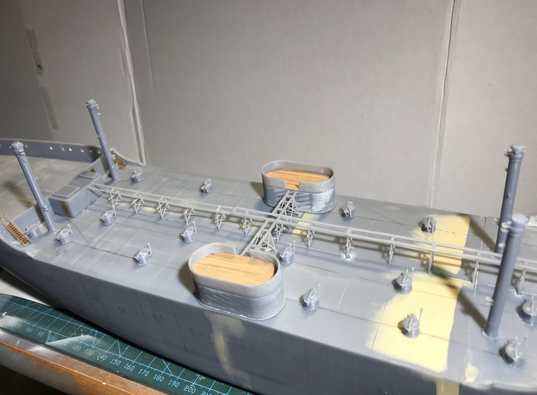
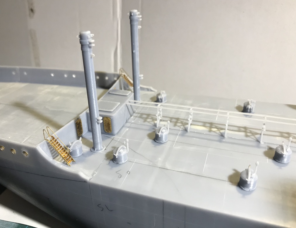
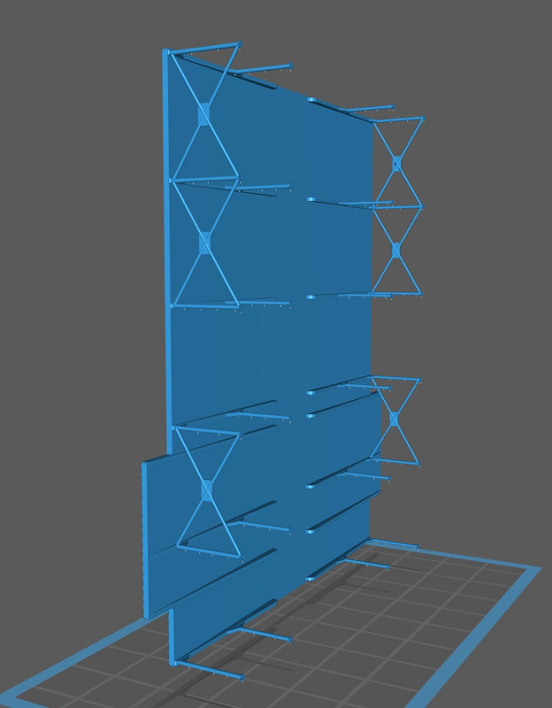
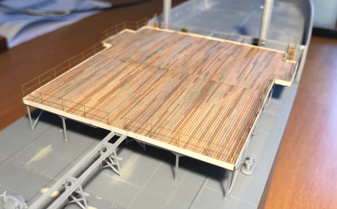
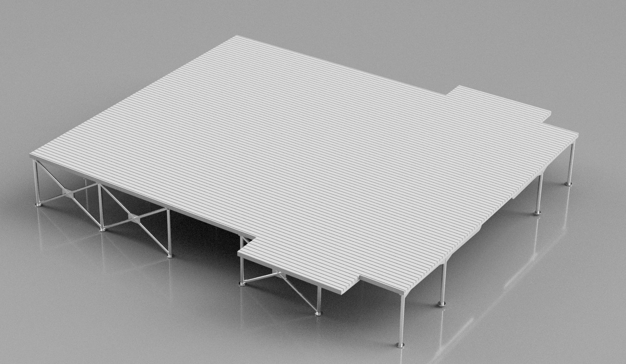
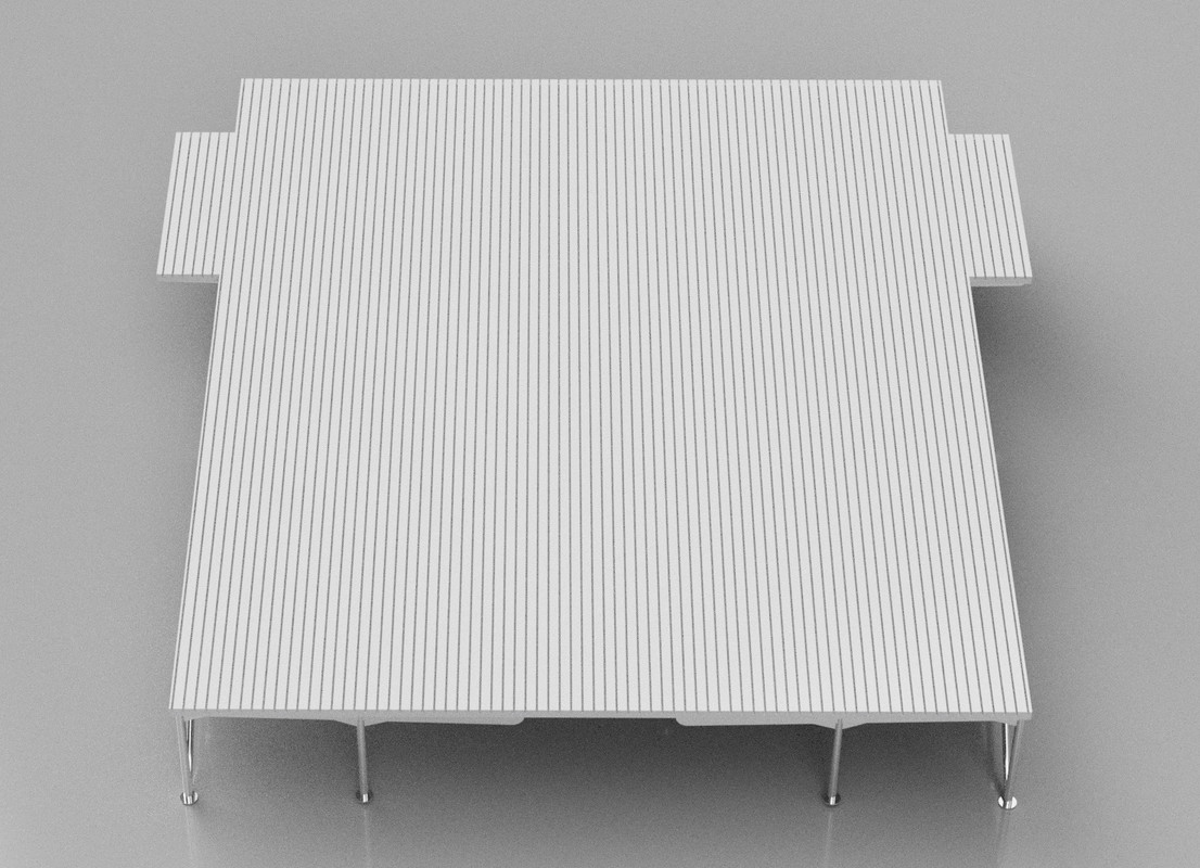
Printing of the platform. The handrails are very thin, a little too thin for the ladder, I think, it's hard to distinguish them...

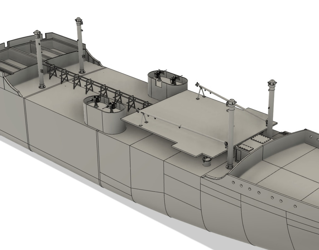
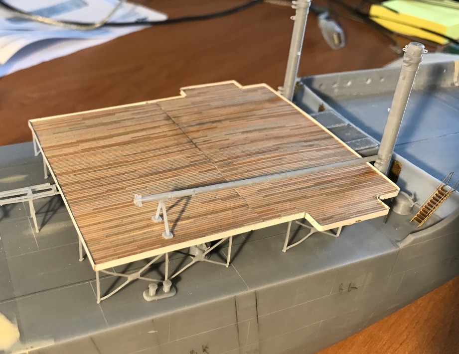
I laid flooring, more remains of the wooden bridge of the Bismarck. I recovered some of the rest of the PE board to make the surround of the platform. It finishes the deck well.

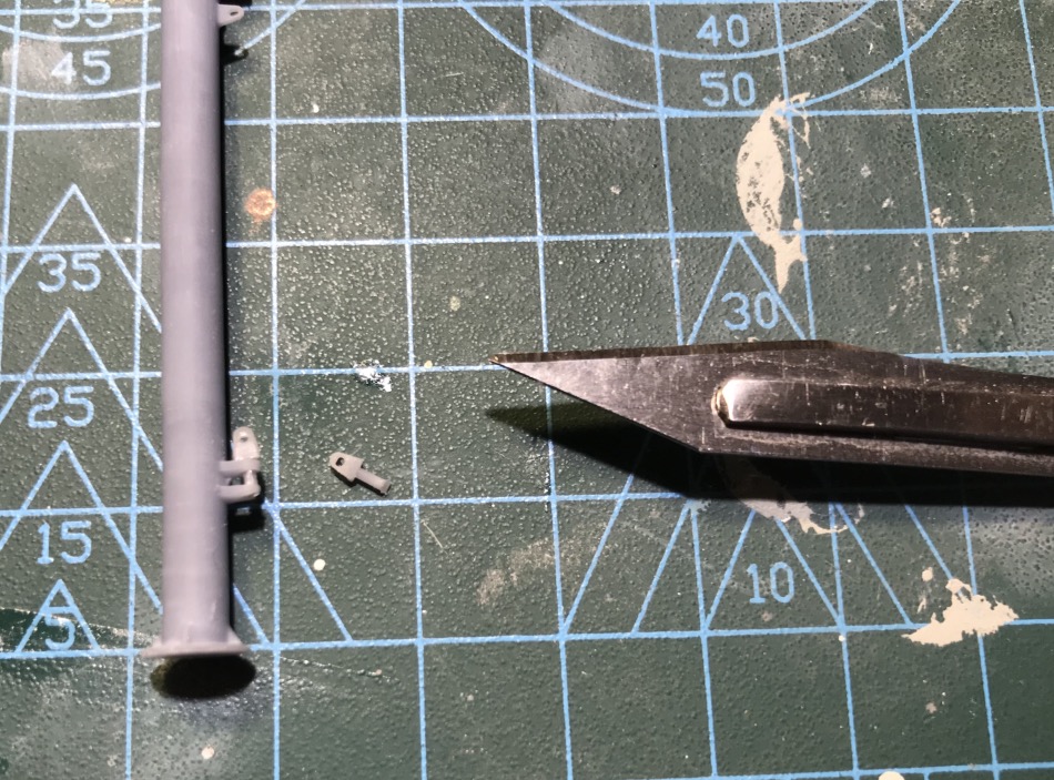
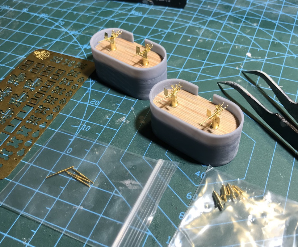
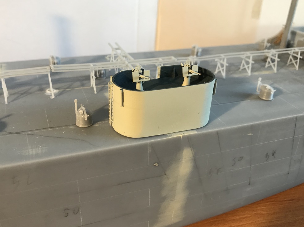
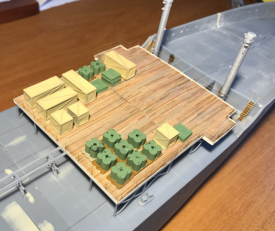
The supports of the platform are extremely thin, I broke some by clumsiness, replaced by piano wire. I had cans and crates in stock, I placed it for fun, nothing is glued of course, not even the platform because there are a lot of pipes to install underneath and paint to apply.

I have the winches for the masts to draw. I would put an airplane engines or two on rack on the platform, I have some in 3D stock, double star and single star.

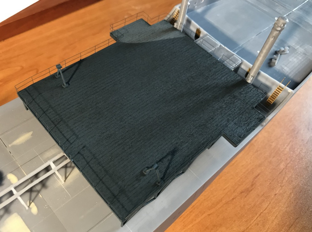
The platform will be painted in dark blue USN 20B at least most of it according to the Dazzle plan and 5O Ocean grey.

Image

Image

Image

Image

Image

Image

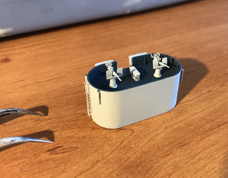
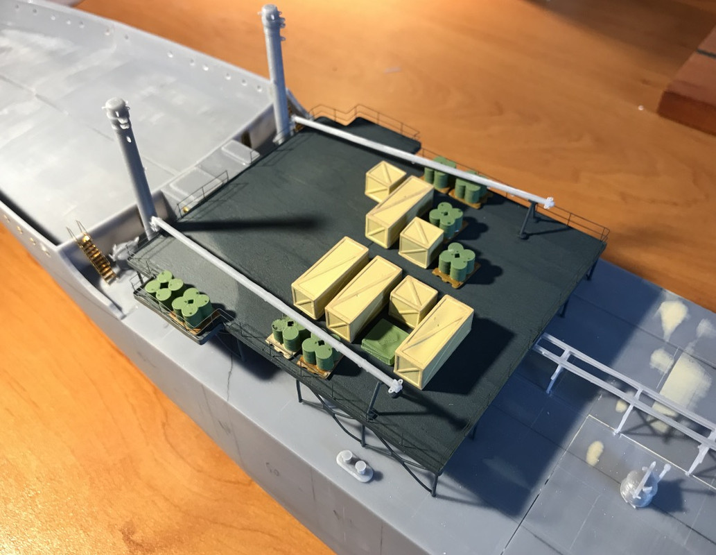
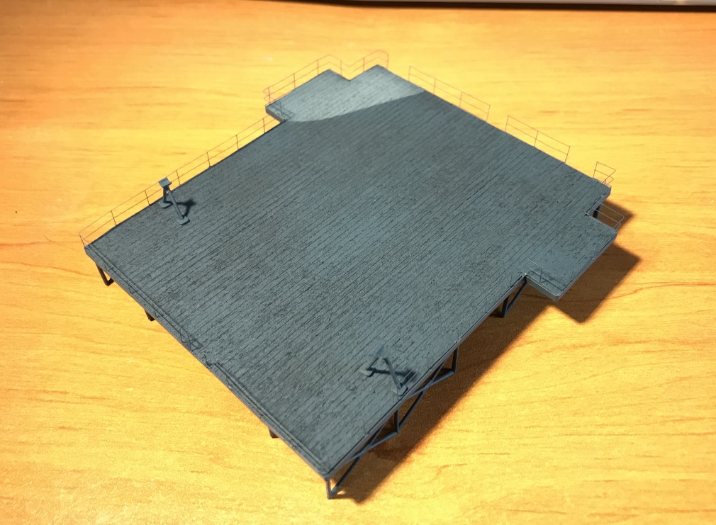
Painting of the platform. Too bad you can't see the floorboards anymore. Should've used a floor with the grooves carved in... Scaledeck's flooring isn't really made to be painted.

Image

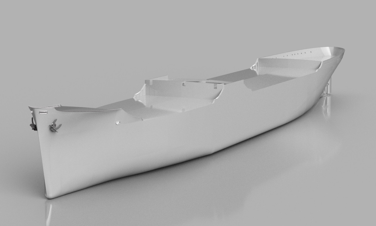
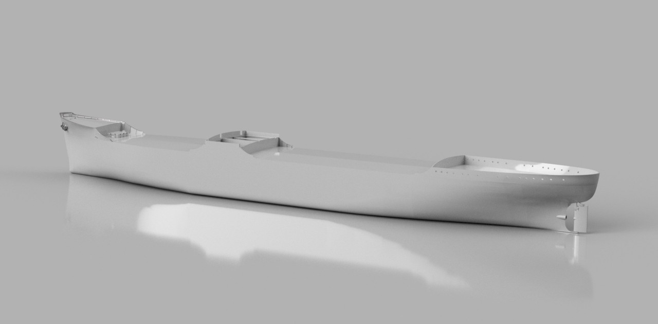
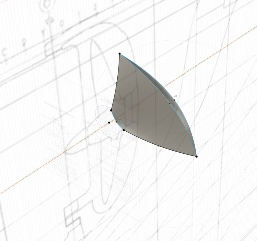
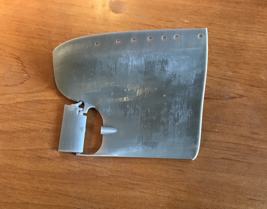
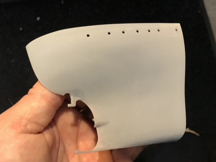
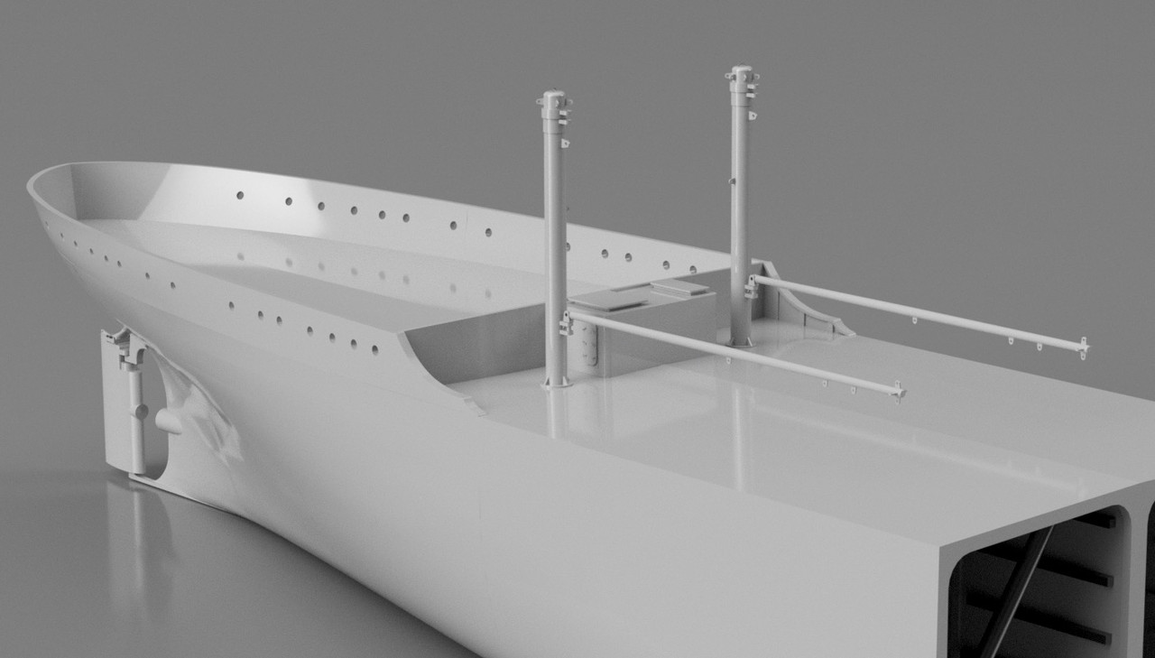
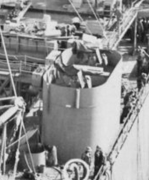
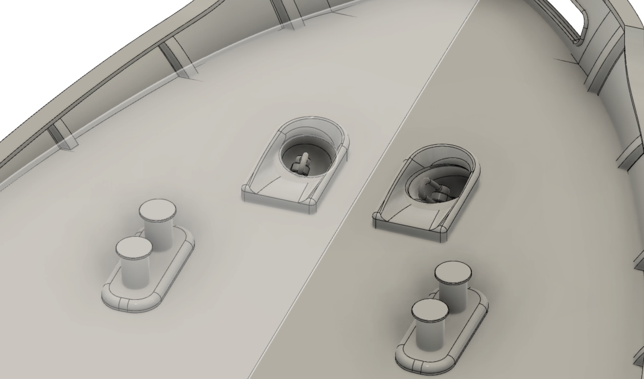
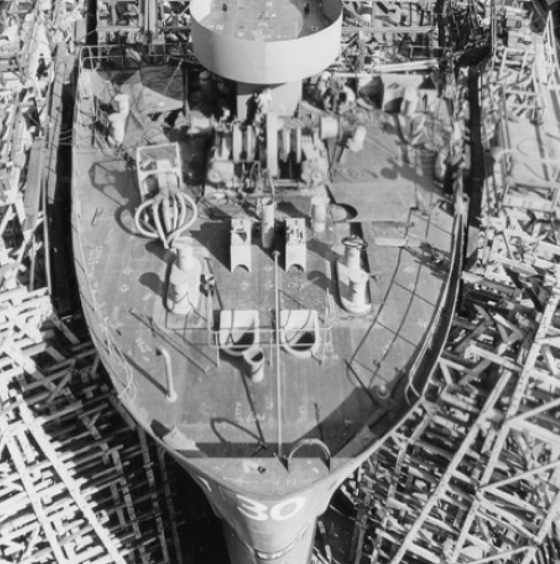
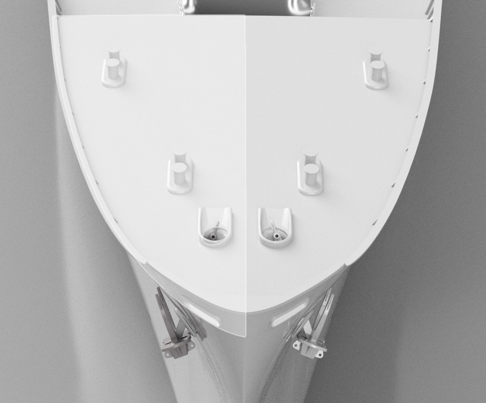
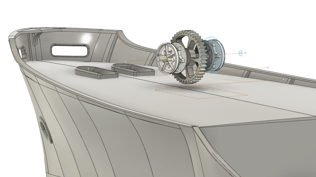
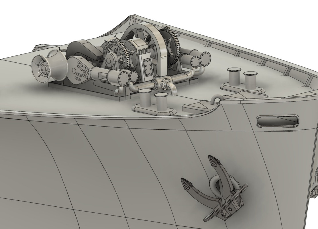
I drew the tops of the hawse pipes tonight.You'd think it'd be easy to draw, but it's not so easy...

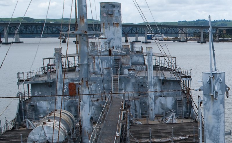
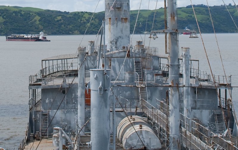
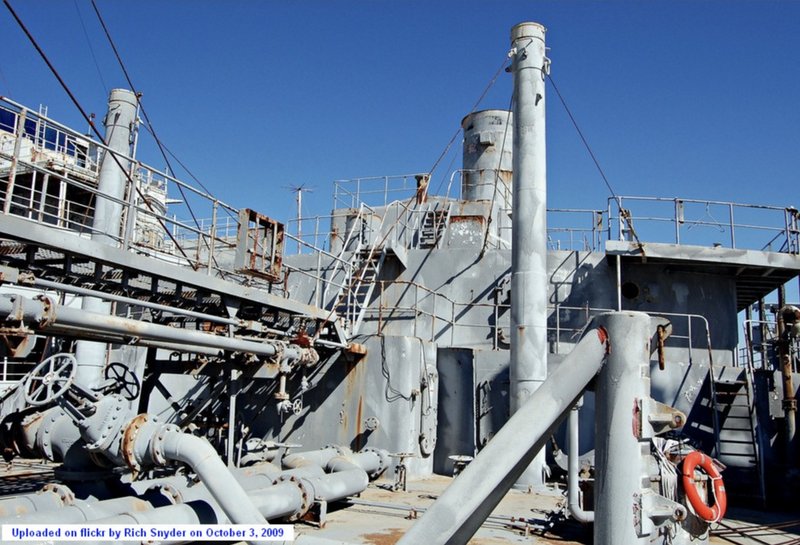
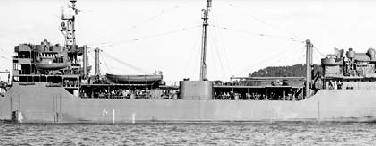
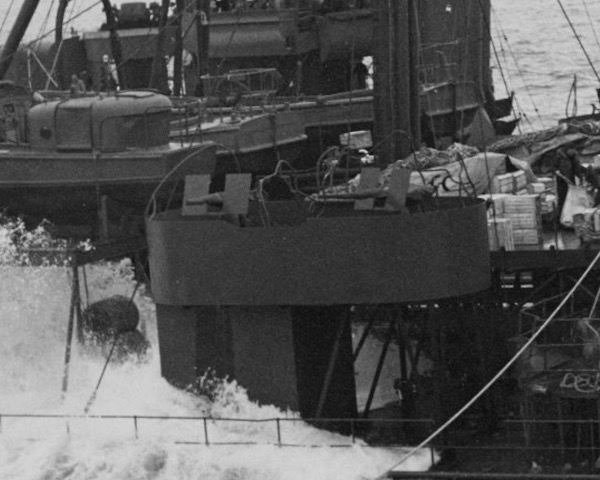
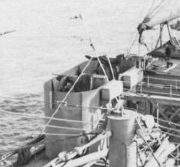
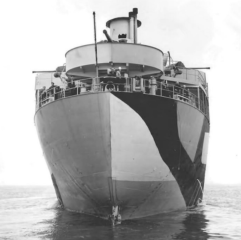
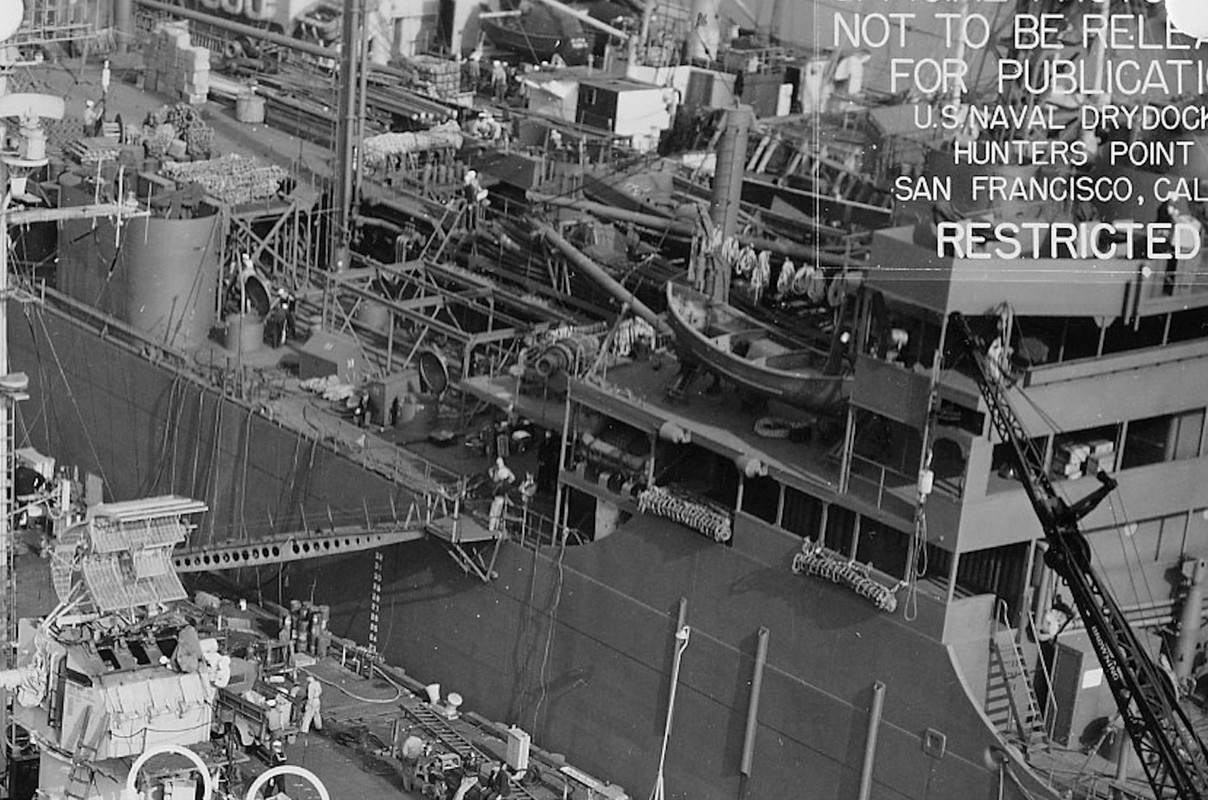
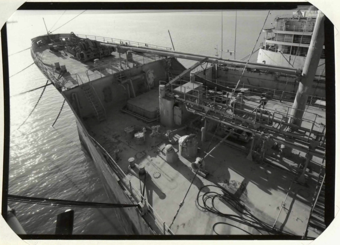
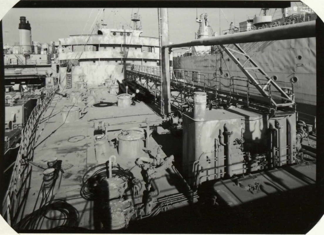
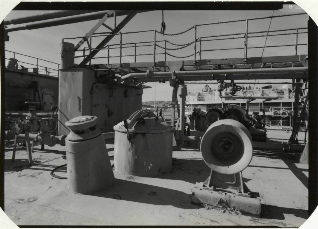
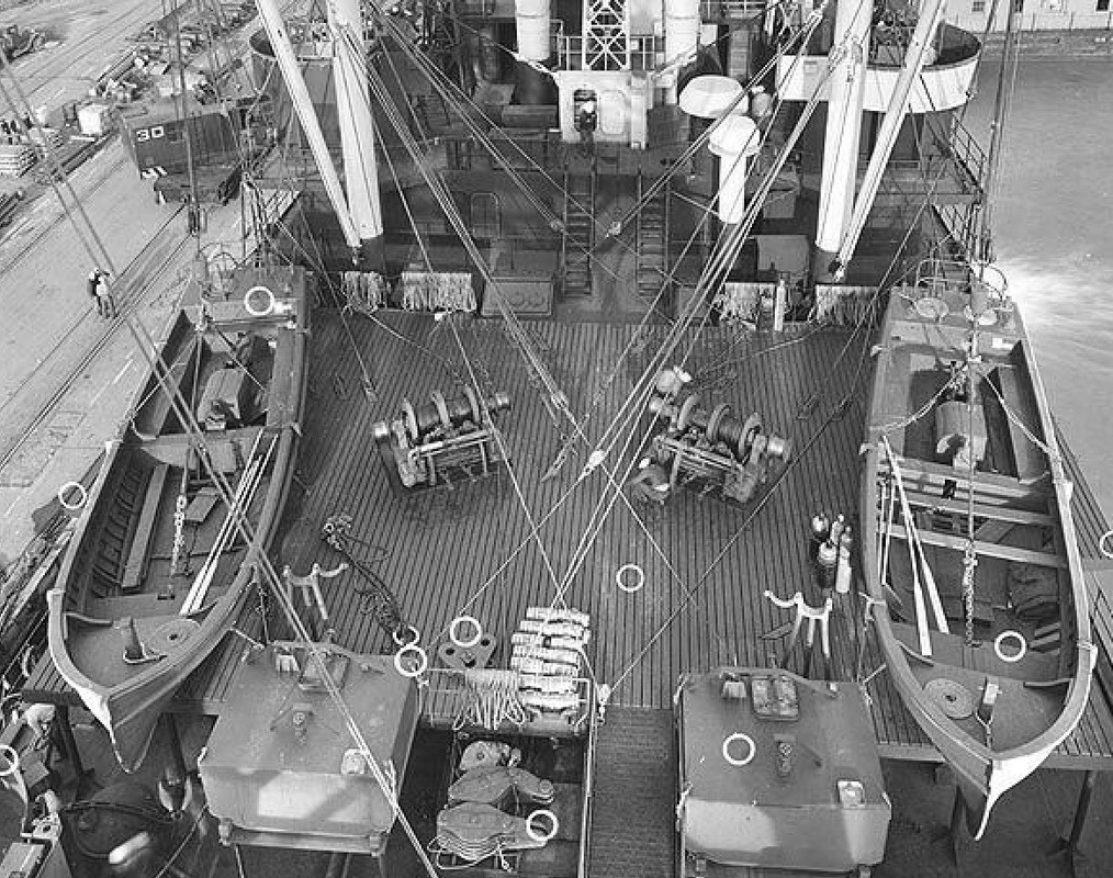
I've got some excellent pictures to help me of the forecastle.

Image

Image

Image

I gave myself a day's thought as to whether I should erase the blackboard, I wasn't satisfied enough with this element, it was acceptable but nothing more, and as I don't want to blame myself for not having done the reasonable maximum, I decided to do everything over again as I should have done, it happens to us all, it depends where you place the cursor...

That's also the flexibility of 3D printing, it's not good, we rectify, and print again. The railing is lost and the rest of the recovery PE too, but I still have some left, and a bit of paint... And a lot of hours, but this is free...

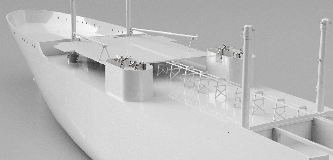
Here's the result, rather encouraging..

Image

I got closer to the floor design in this photo.

Image

Image

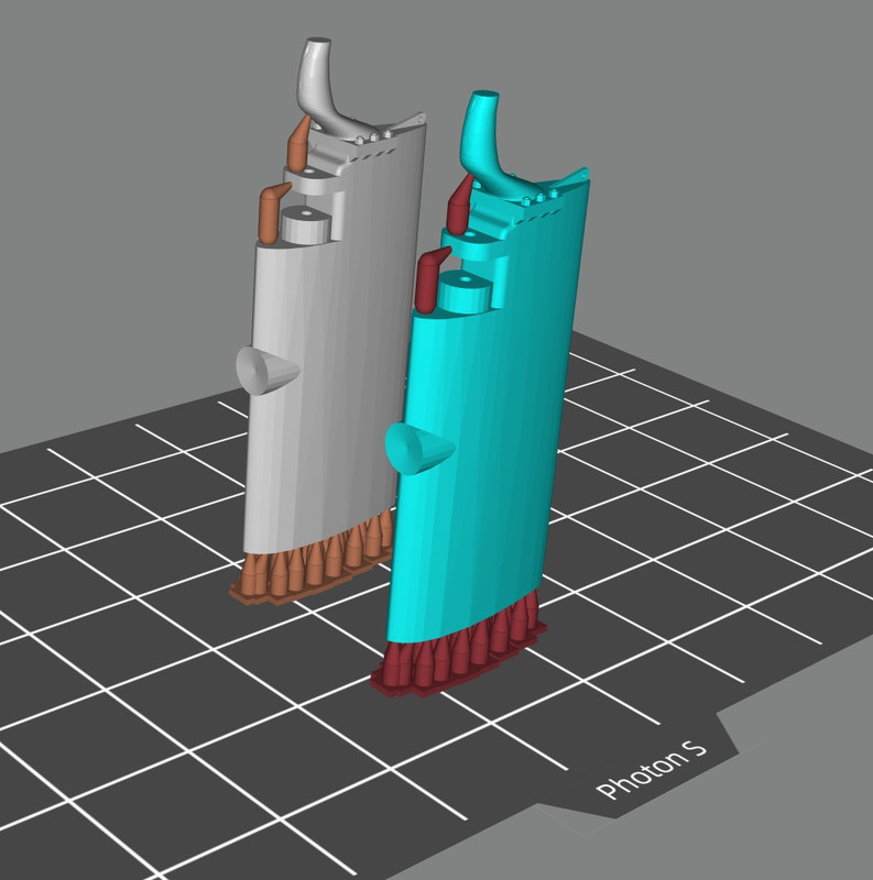
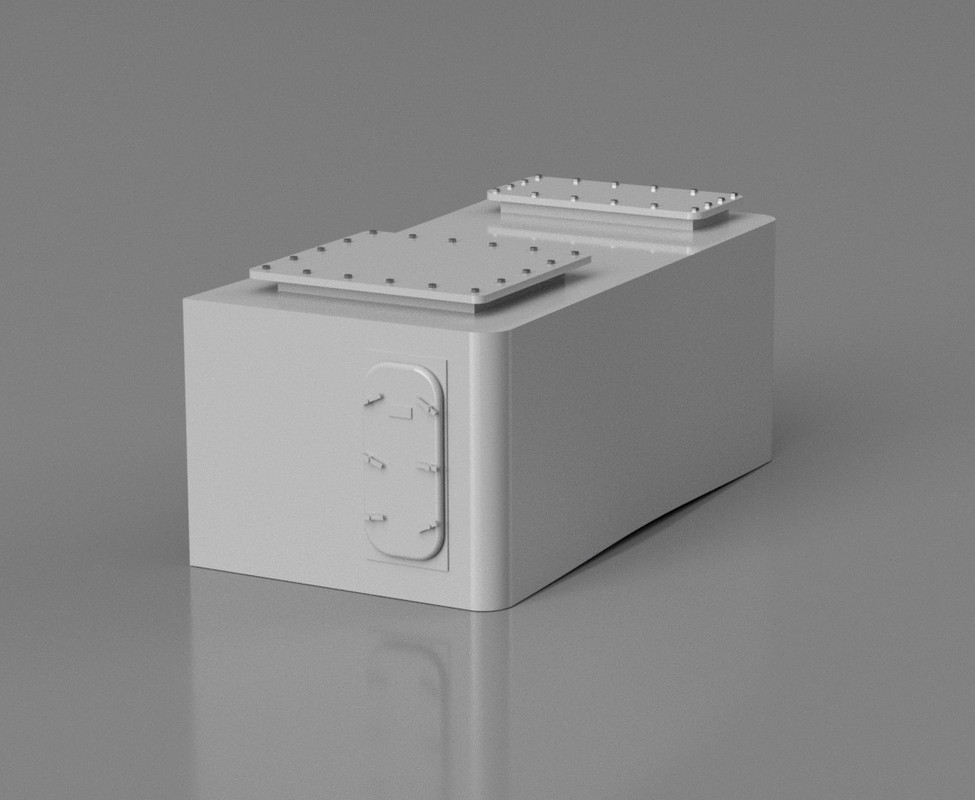
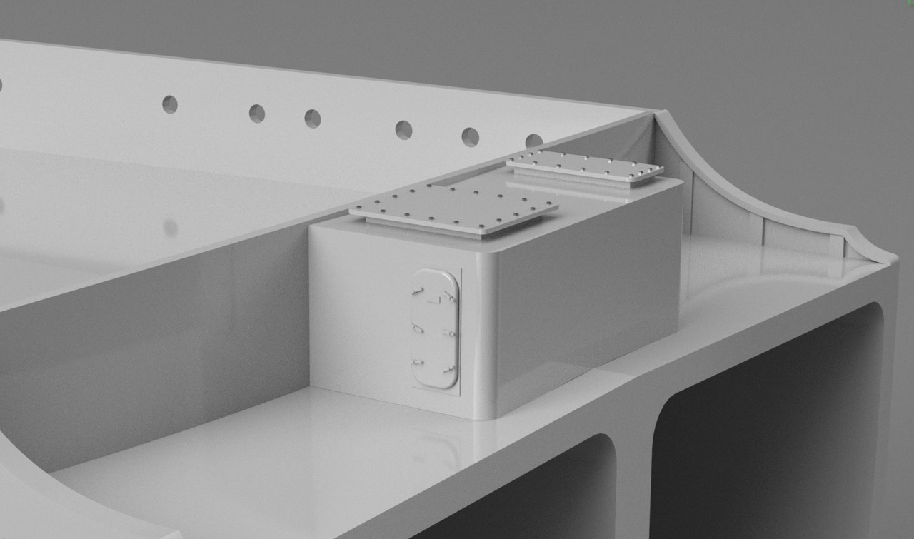
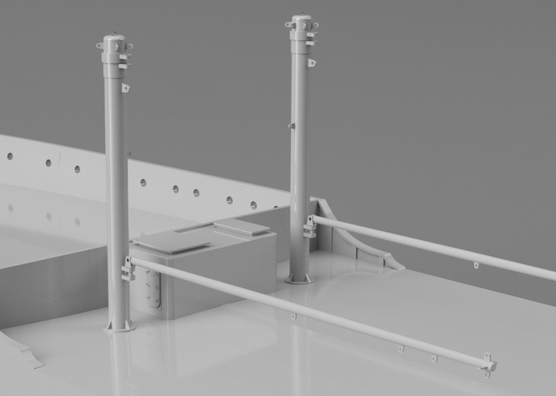
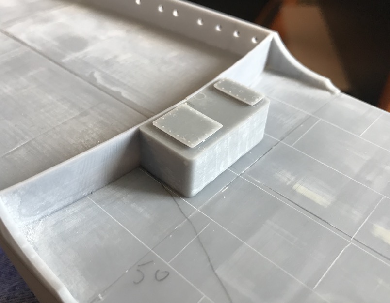
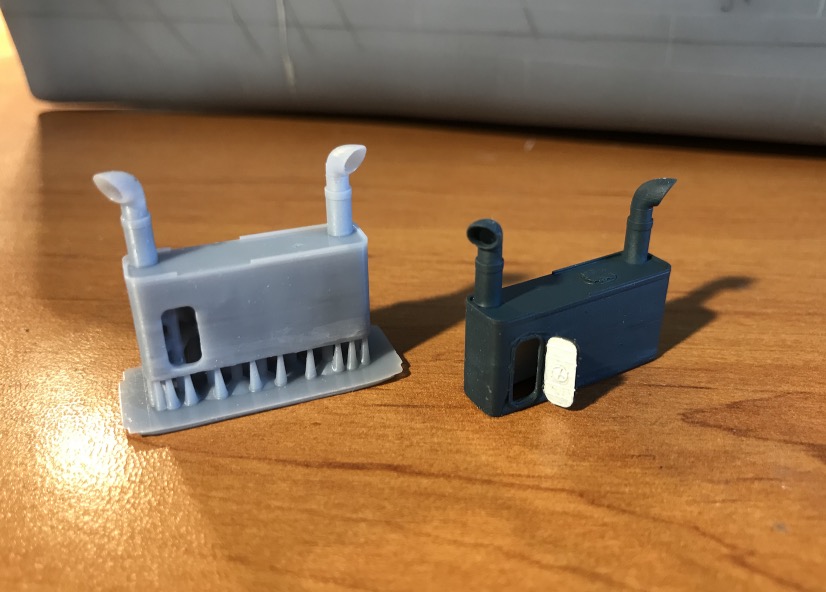
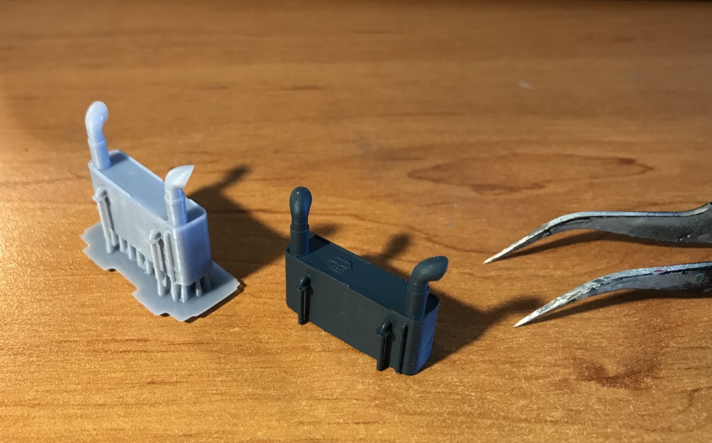
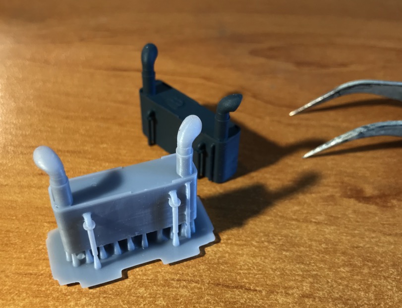
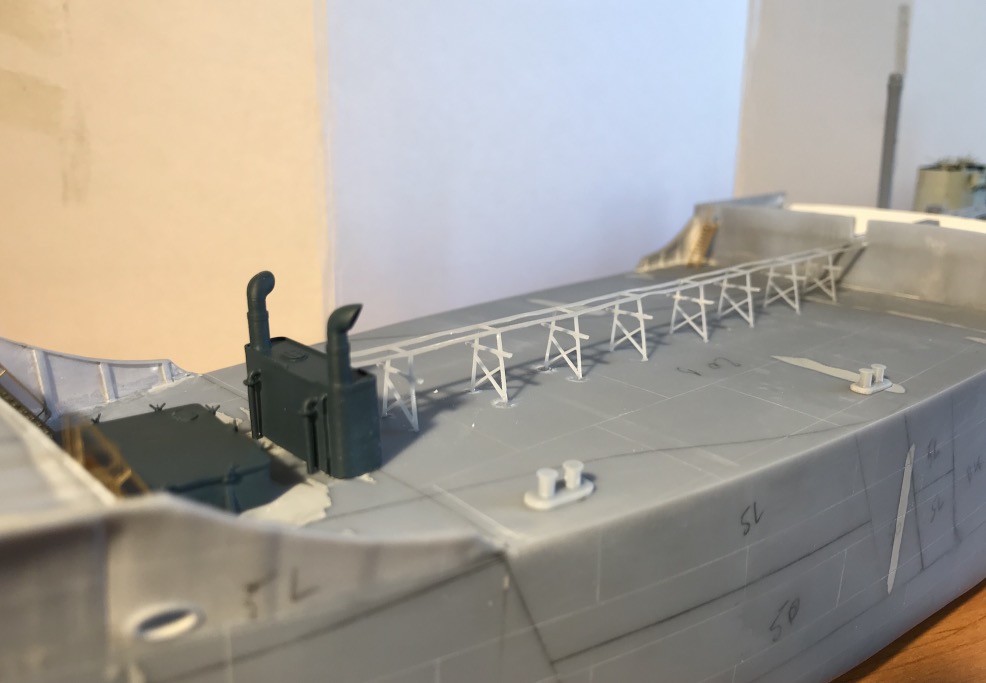
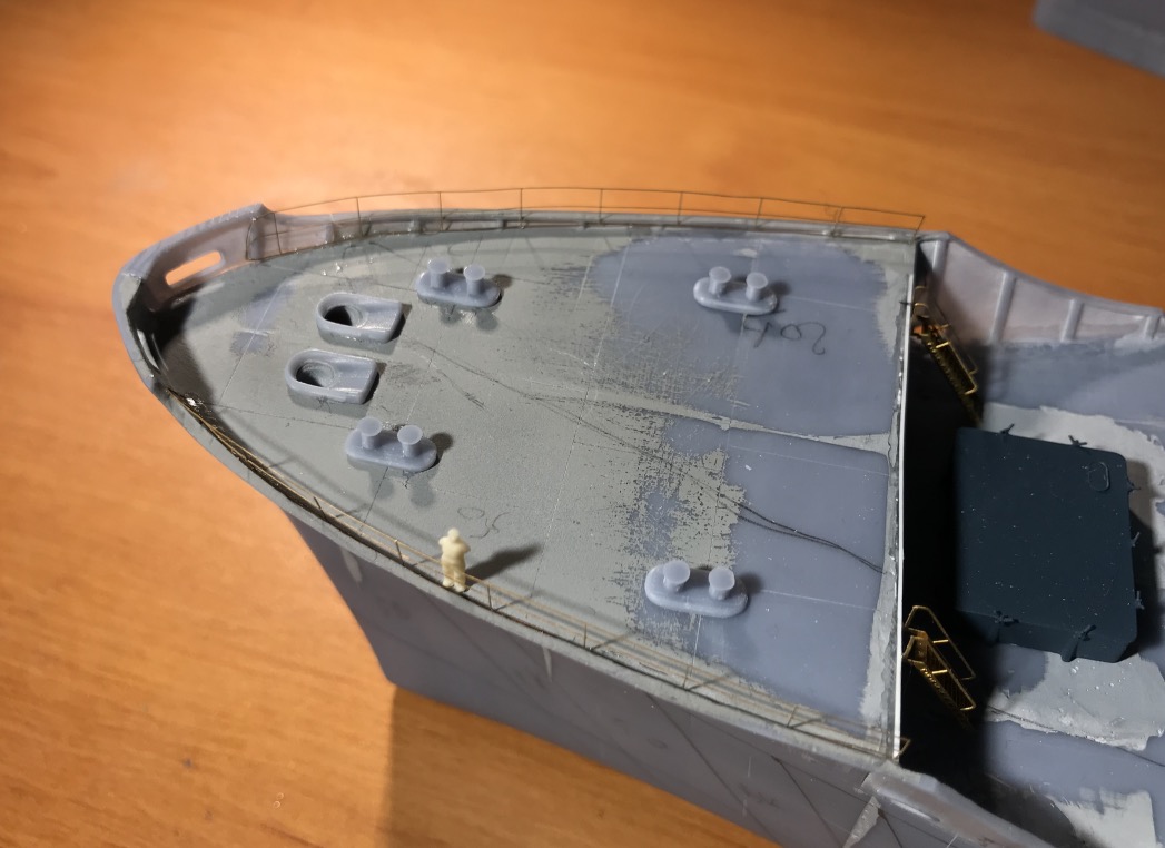
I designed a ventilation funnel for the forecastle, and a gooseneck.

Image

Image

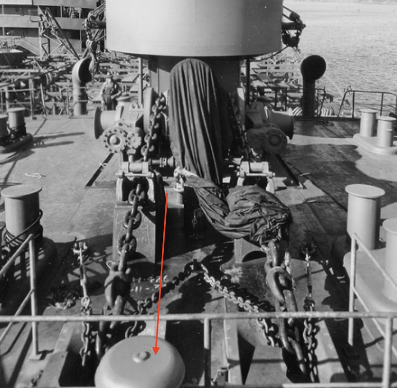
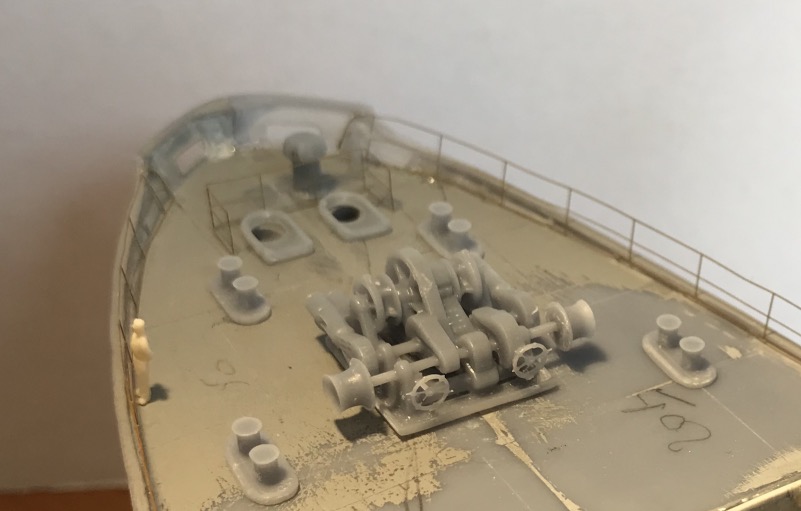
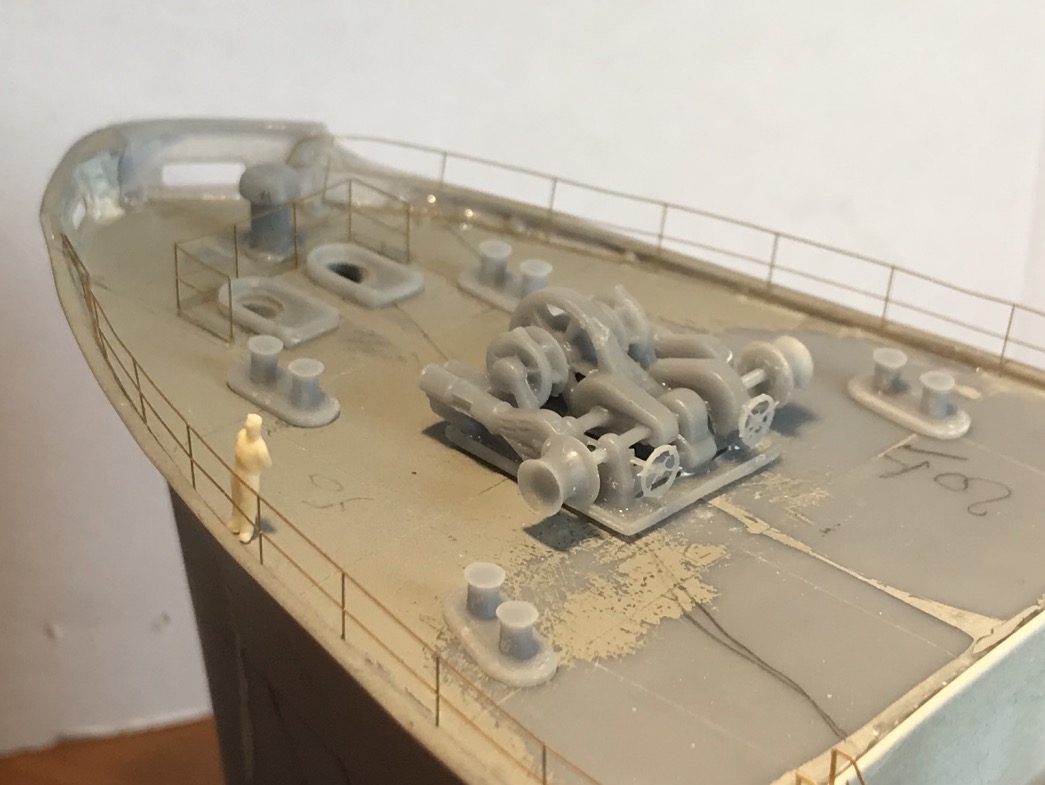
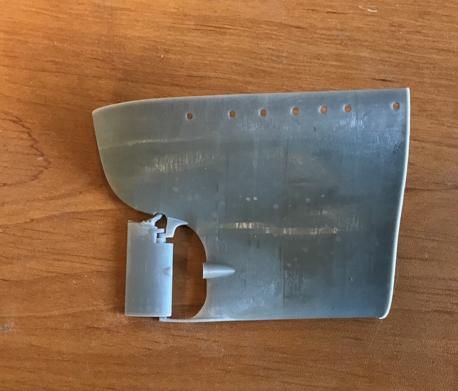
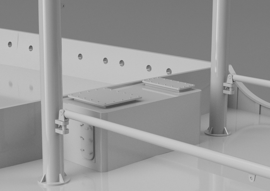
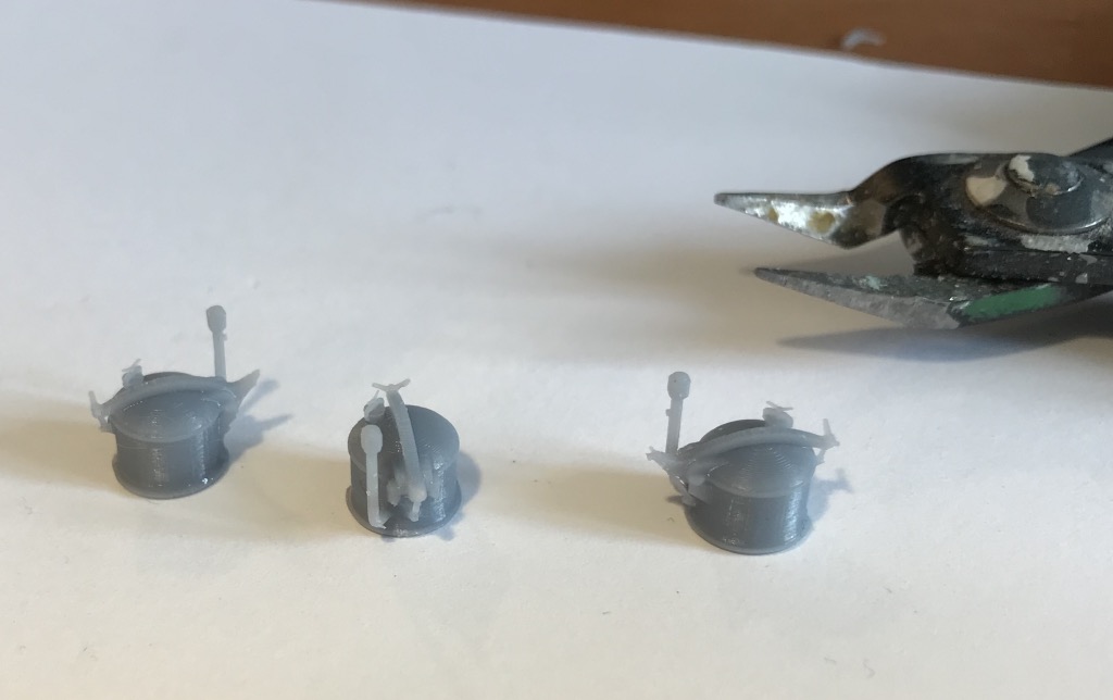
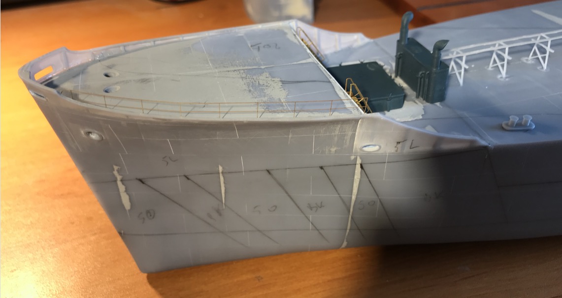
Precise positioning of the tops of the hawsers and gluing.

Image

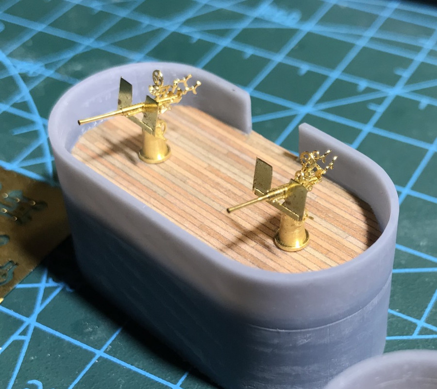
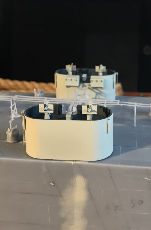
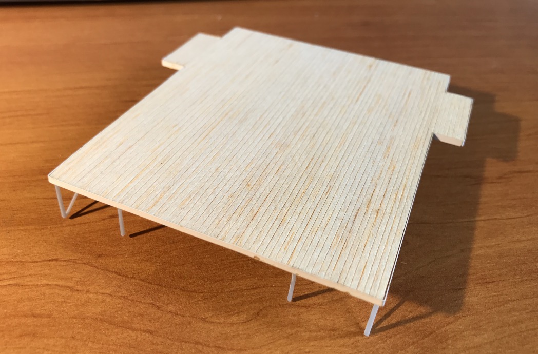
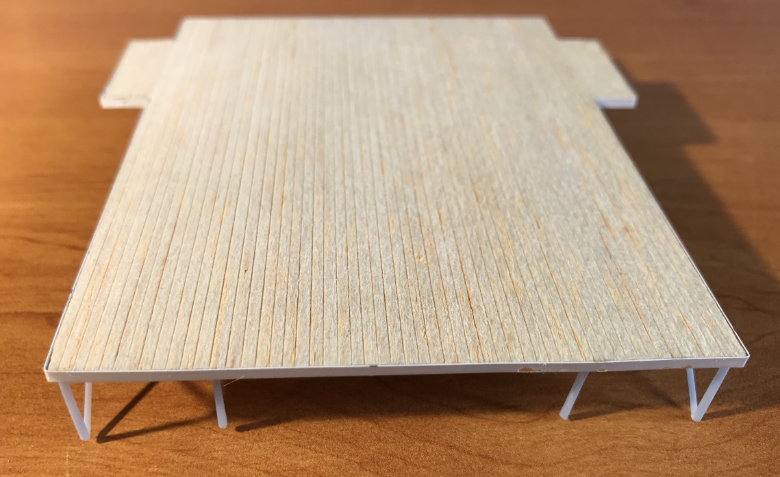
Not being satisfied with my second version of the platform, I took out of my big stock my best balsa wood, what better than wood to represent ... wood.

I kept the some printed material.

I didn't put a hard background ont he balsa, the goal being precisely to have the texture, I traced the slats with a scalpel. Then I painted in black with an aerial to load the grooves, and I applied the 20B always with an aerial in a flat way so as not to cover the black to give contrast.

That's better. :big_grin:

Image

Image

Image

Image

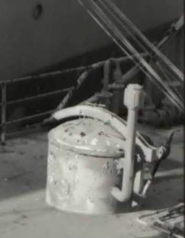
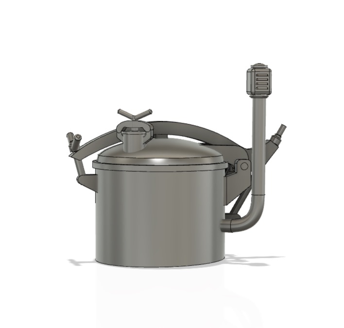
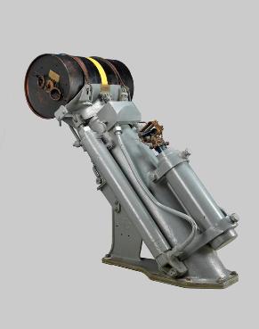
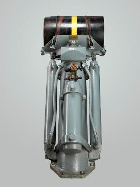
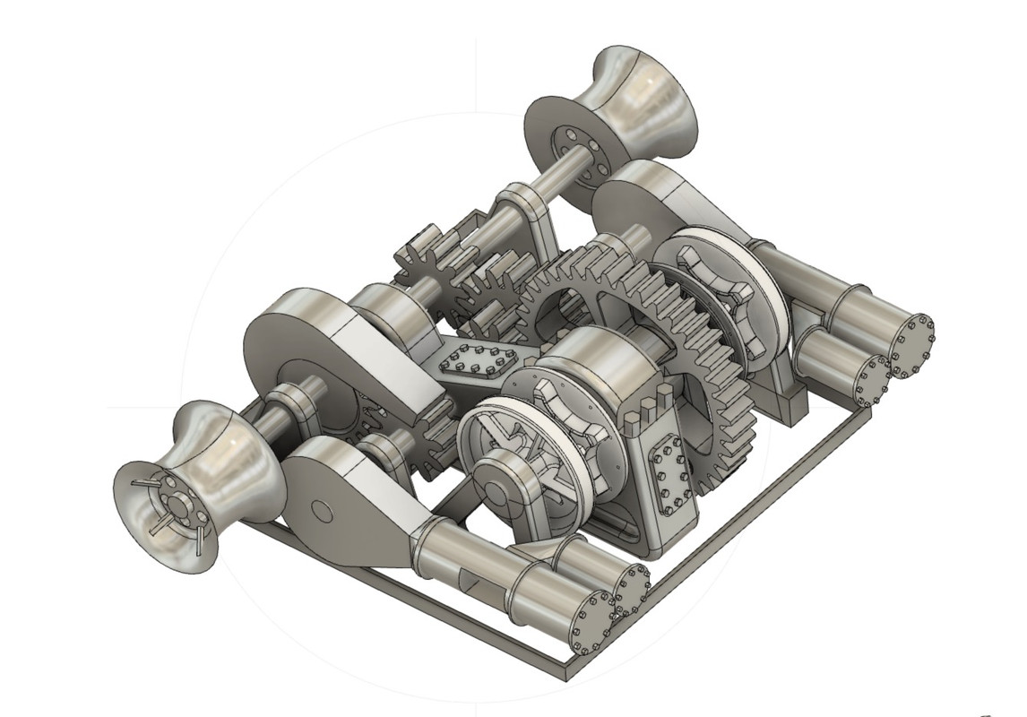
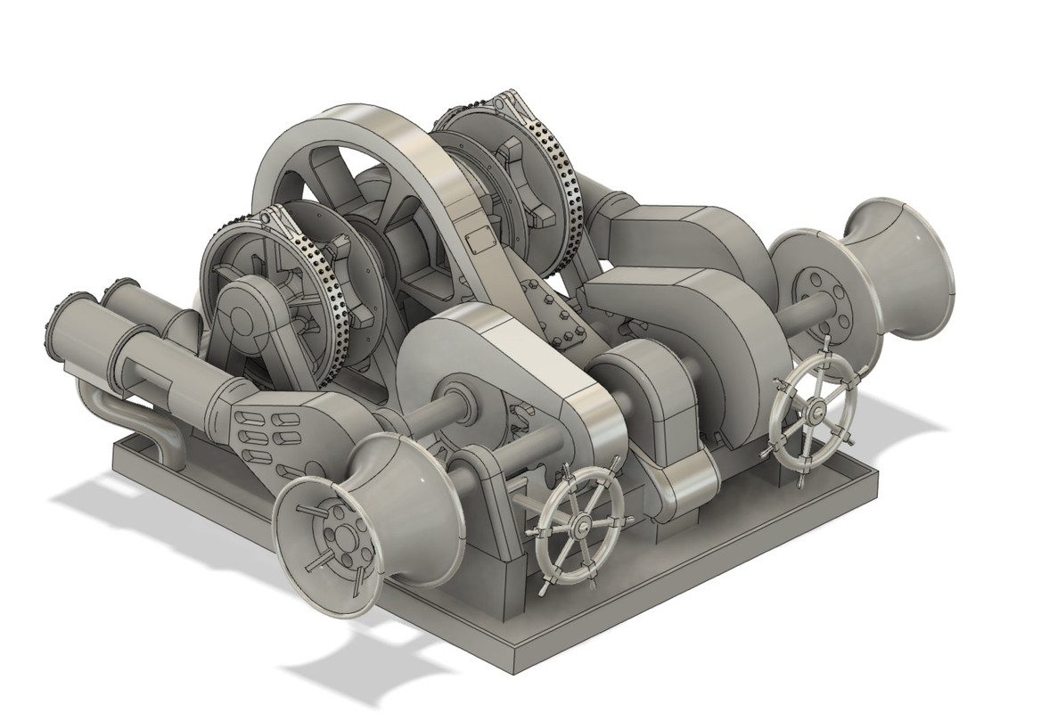
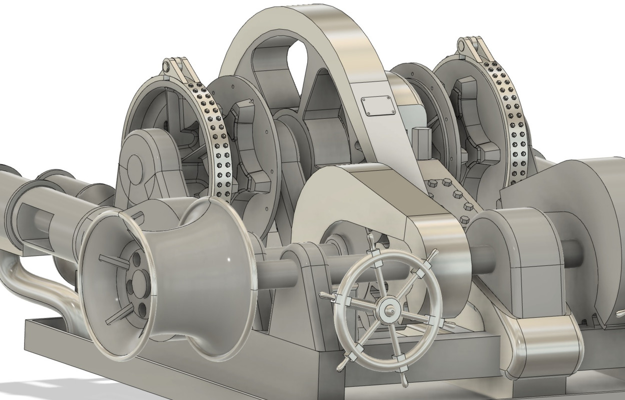
I started the drawing of the steam windlass. I'll simplify it of course, although it's always tempting to overdo it...

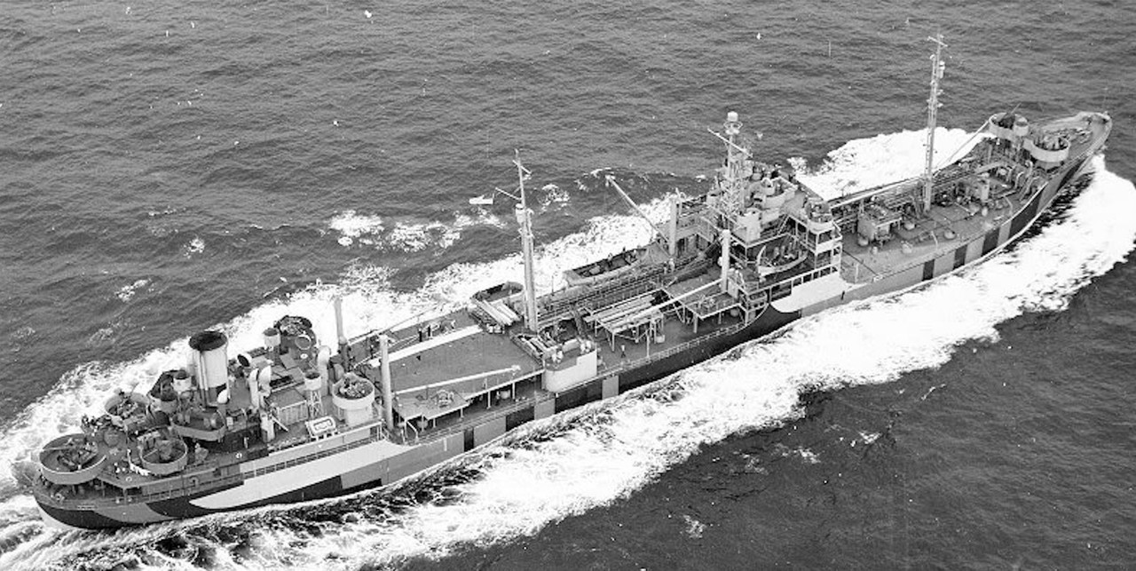
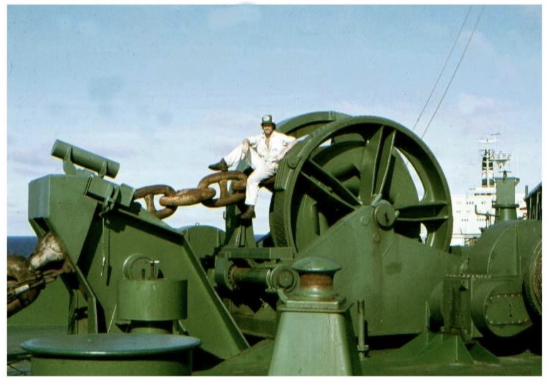
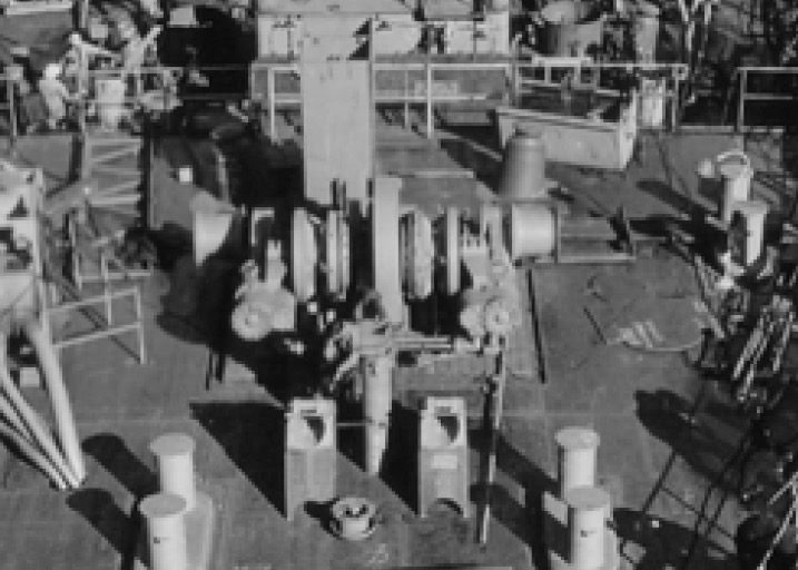
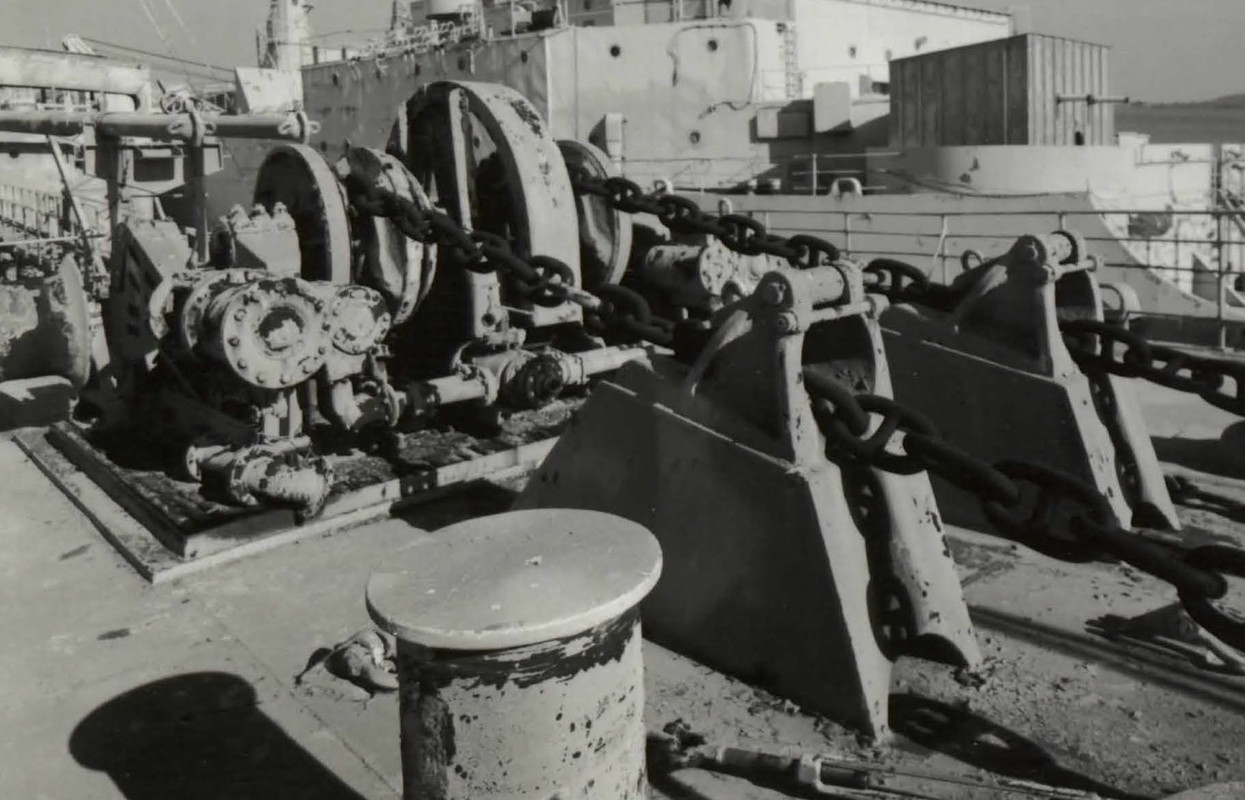
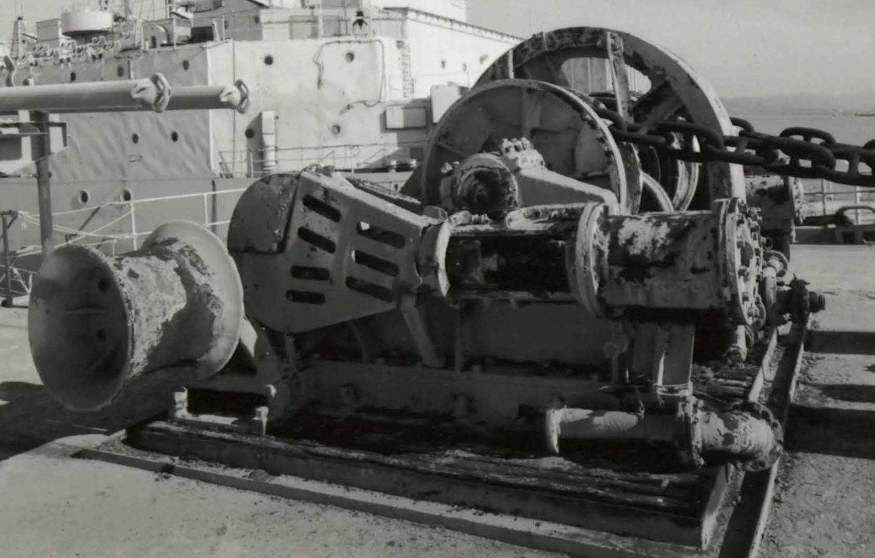
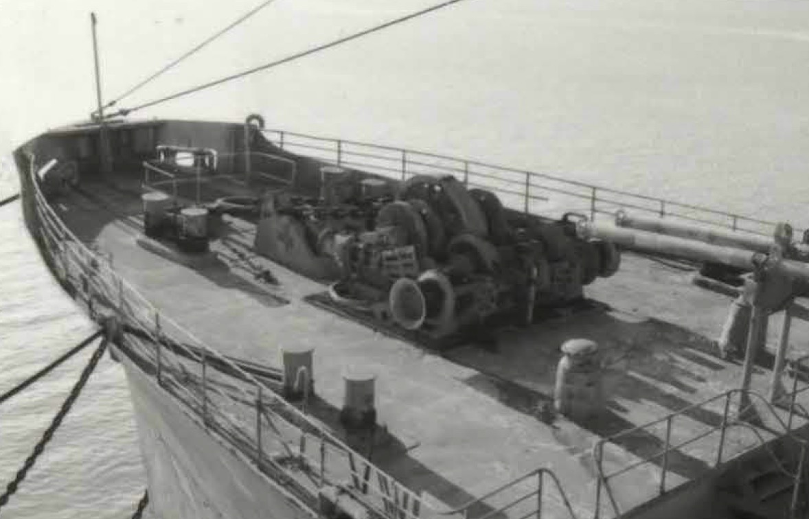
Luckily I have good pictures, but only pictures, no plans. So you have to make do with it, but I know this kind of equipment well from having maintained or repaired it. It necessarily helps, because the principle remains the same. The design of this kind of machine hasn't evolved much. The engine can be steam, electric (for the small ones), or most often nowadays hydraulic, on a big ship like a super tanker VLCC or ULCC, it's monstrous in size ...

Photo from the net. 340,000 tons ULCC (Ultra Large Crude carrier) "Coastal Corpus Christi" tanker, mouth of the Amazon in 1981.

Image

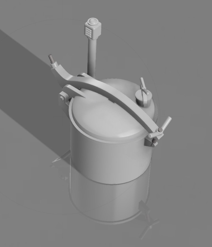
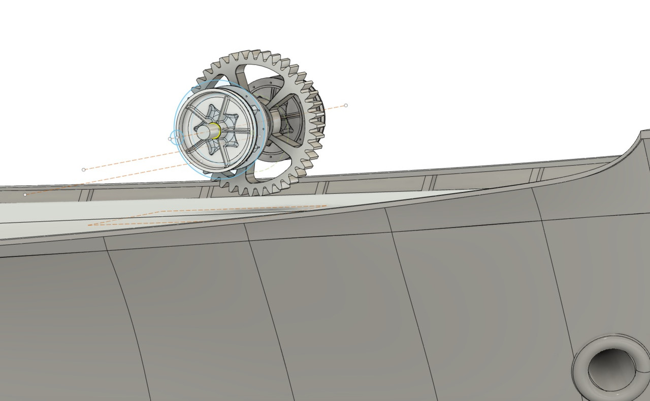
Luckily I found a free 3D lifter (the chain is embedded in this crown), which saves me time, because it's long to draw, the shapes are complex, but not impossible to achieve at my low level by taking the necessary time.

Thanks to Alexandros Vassilantonakis.
https://grabcad.com/library/anchor-winch-2

Image

Image

Image

Image

Image

Image

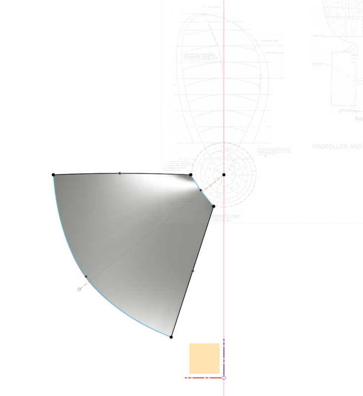
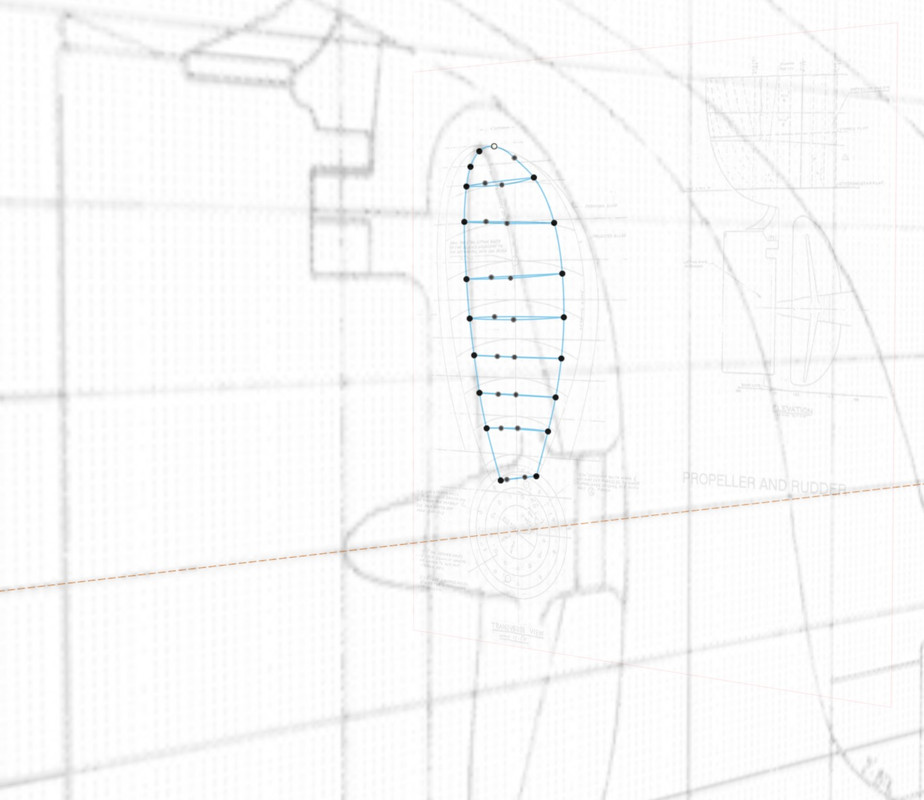
You can see the construction axes, representing the 3 shafts.

Image

Image

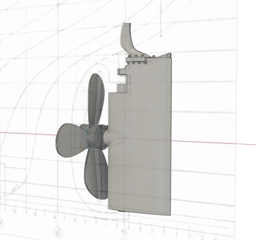
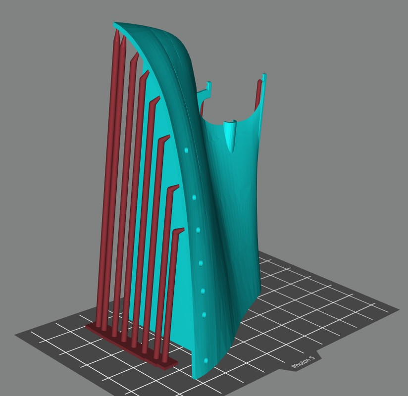
I'm curious to see what it's going to look like in 3-D printing, maybe a dung beetle...

Image

Image

Image

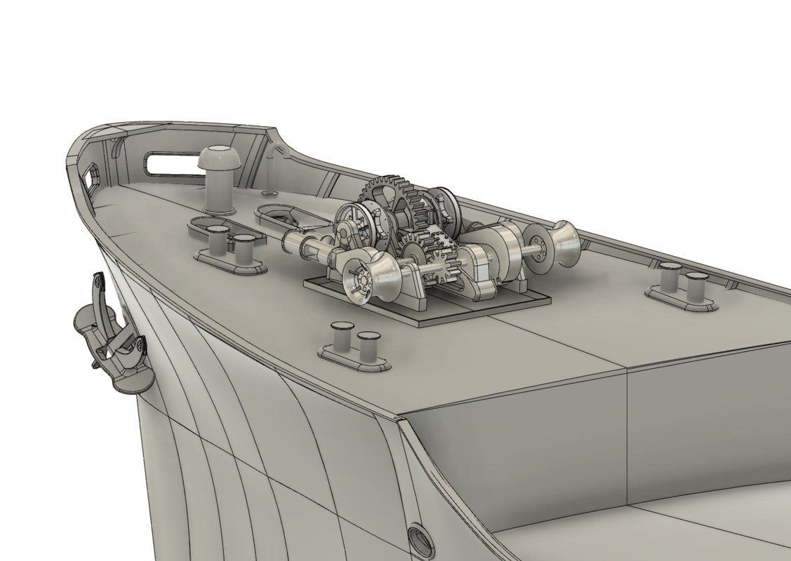
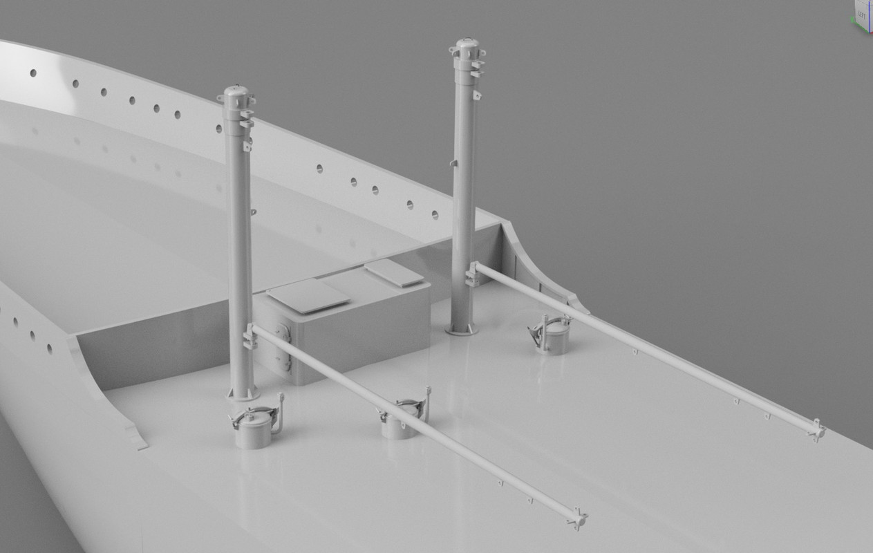
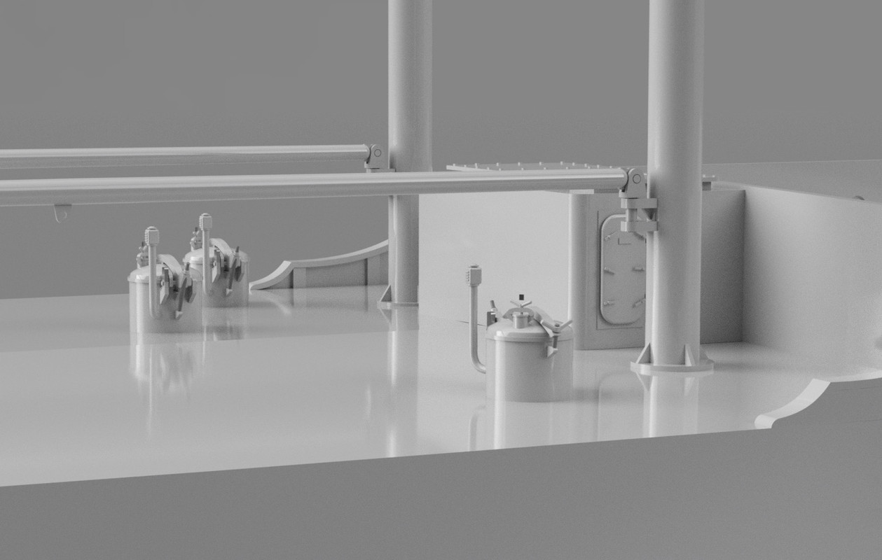
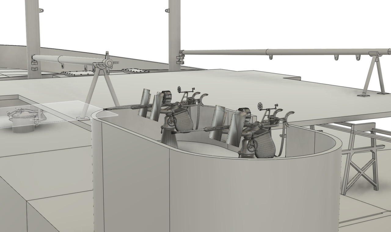
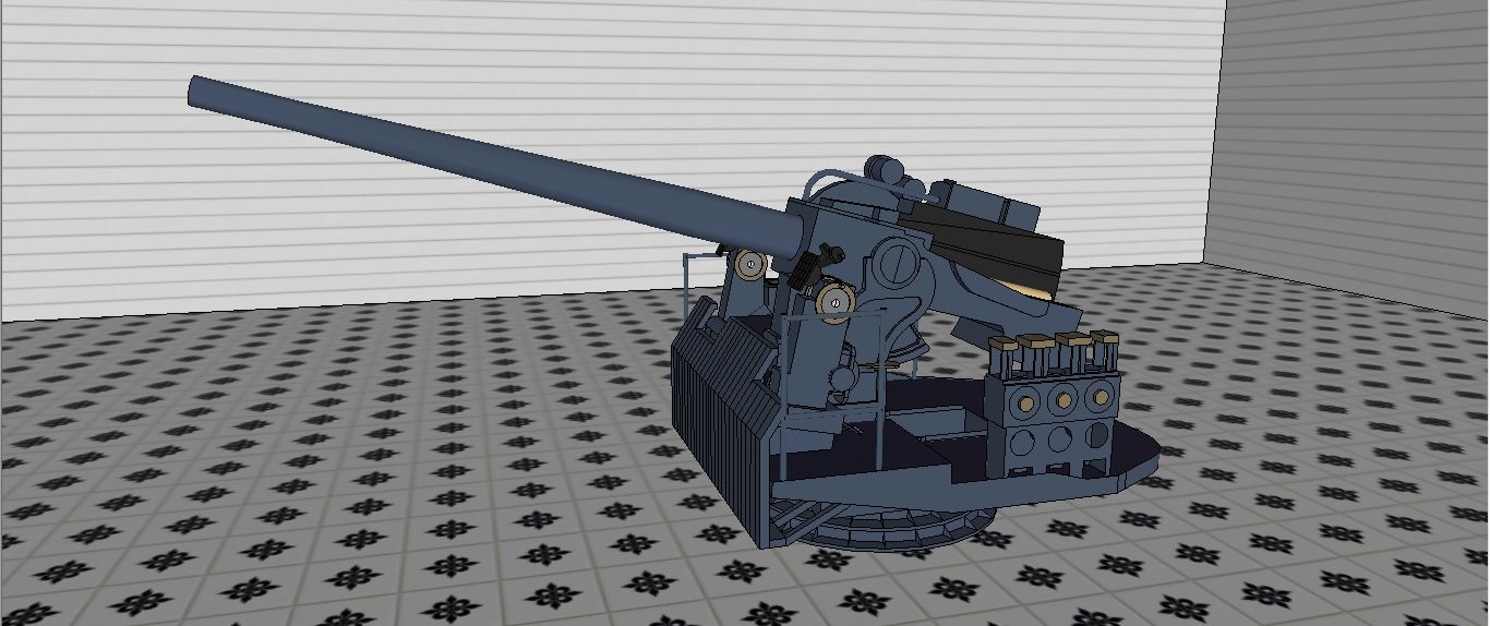
I have finished this windlass, but other winches are to be designed; I see 4 types on board. the forward main deck manoeuvring winch. The cargo mast winches, all identical. And the aft manoeuvring winch under the 5-inch 38 gun platform. They're much simpler to make.

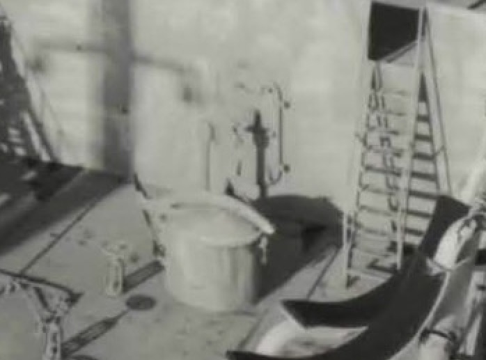
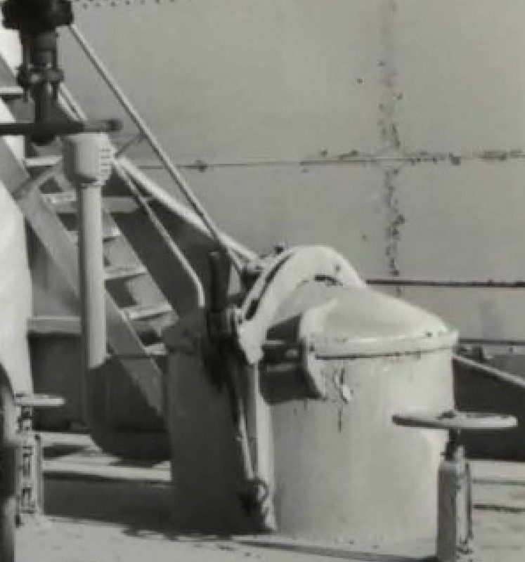
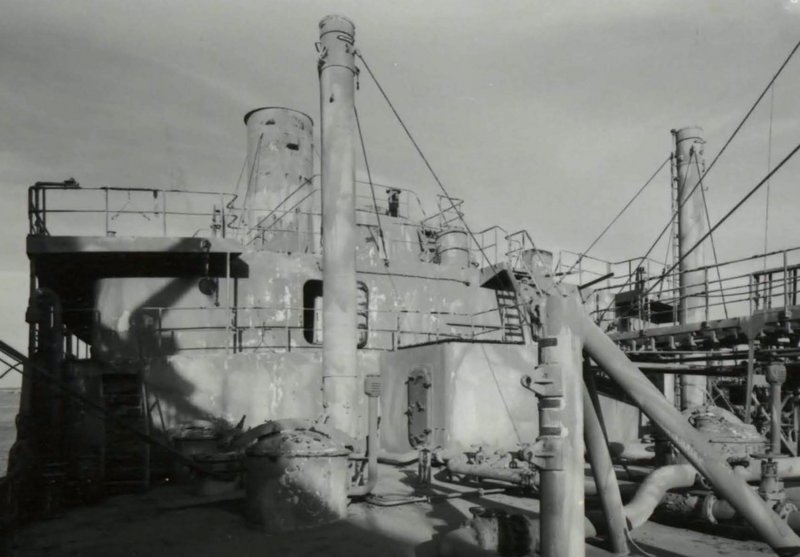
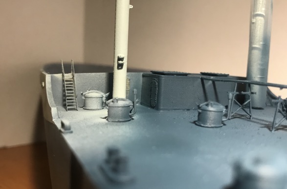
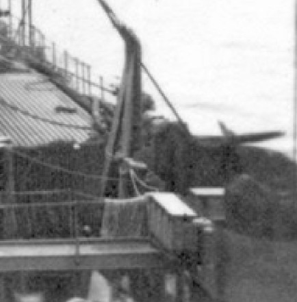
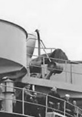
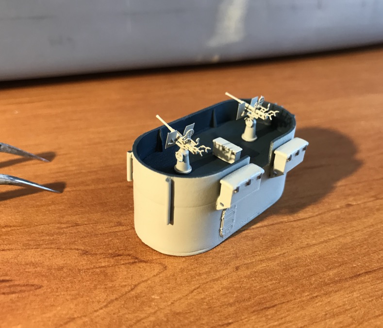
I found a rare small picture of poor quality of the aft maneuver of a T2, it's better than nothing...

Image

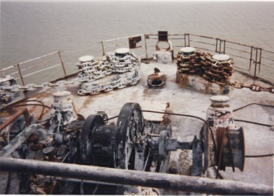
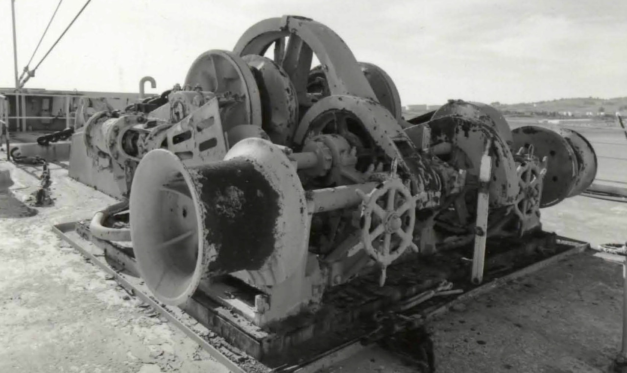
I love the steering wheel-shaped brake pads!

Image

Image

Image

Image

Image

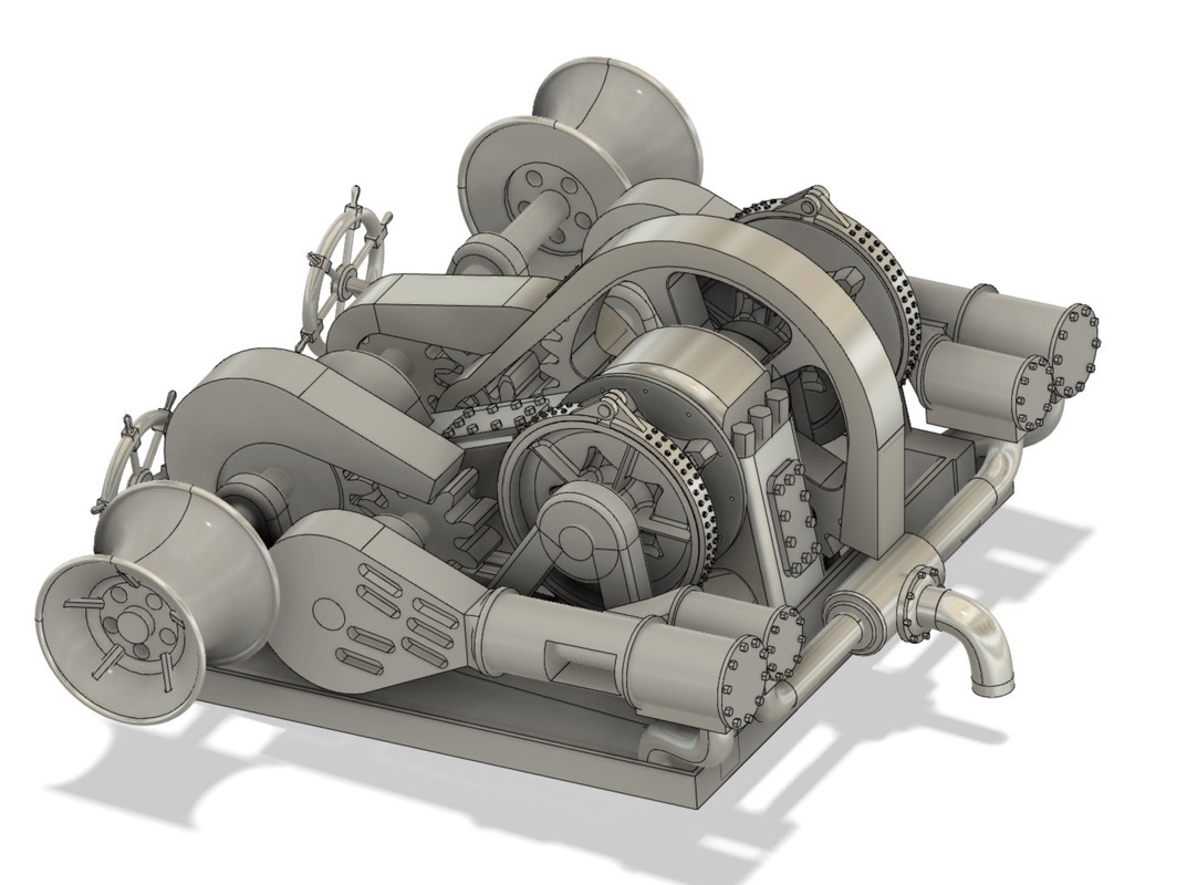
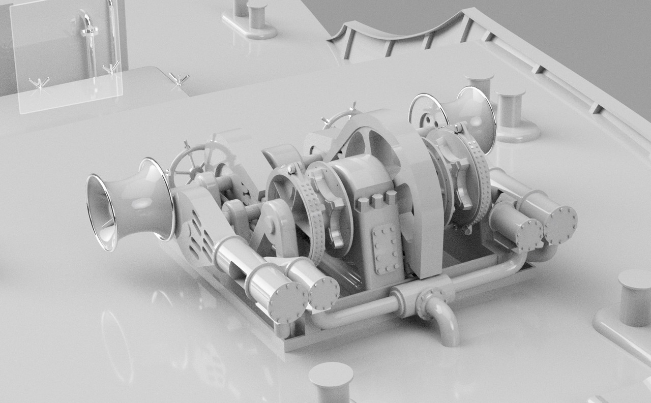
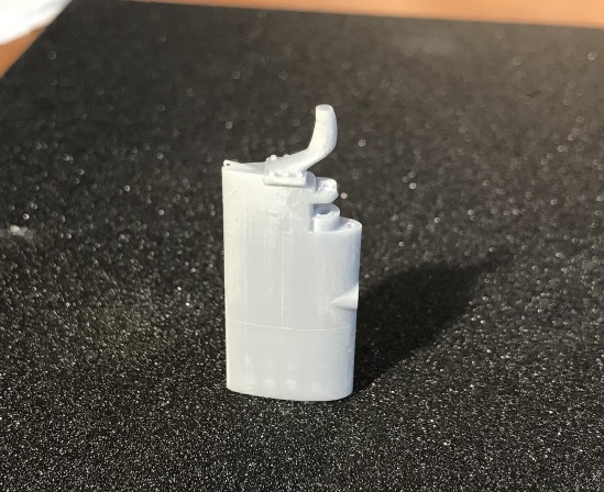
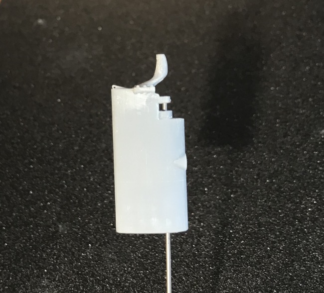
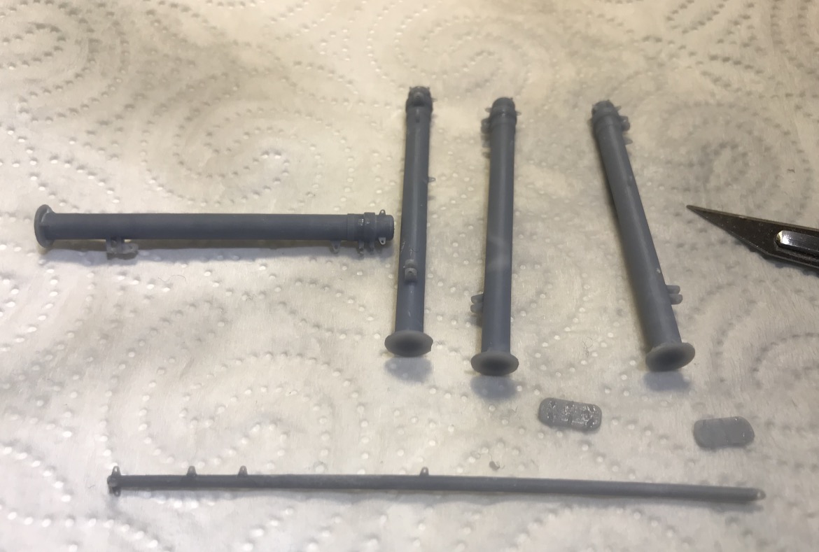
I reduced the size to 85% when I printed it. It came out pretty good. I'm pretty happy. The brake wheels are pretty well out, the arms are very thin, I could replace them with some PE I have, I'll see.

Image

Image

_________________
Pascal

•Battleship Bretagne 3D: https://vu.fr/FvCY
•SS Delphine 3D: https://vu.fr/NeuO
•SS Nomadic 3D: https://vu.fr/tAyL
•USS Nokomis 3D: https://vu.fr/kntC
•USS Pamanset 3D: https://vu.fr/jXGQ


Report this post
Top
 Profile  
Reply with quote  
PostPosted: Mon Oct 05, 2020 11:42 am 
Offline

Joined: Wed Jan 02, 2013 1:15 am
Posts: 5060
Nice drawings for the steam Anchor Windlass! I've never seen one of these work so I guess they huff and puff, emitting clouds of steam? You were fortunate in being able to find a lot of good photos of this complex piece of equipment. The short posts around which the mooring lines are secured are called "Bitts" and a hawser is a large diameter line. During WWII these were usually "Manila", a natural fiber rope material. Post war most were replaced by Nylon. A major disadvantage of Nylon was it's stretchiness. Under severe strain it would nearly double it's length, turn brown (smokes?) and makes a screaming sound before it parts (you don't want to be anywhere near this if that happens).

Cheers: Tom


Report this post
Top
 Profile  
Reply with quote  
Display posts from previous:  Sort by  
Post new topic Reply to topic  [ 171 posts ]  Go to page Previous  1, 2, 3, 4, 5 ... 9  Next

All times are UTC - 6 hours [ DST ]


Who is online

Users browsing this forum: No registered users and 5 guests


You can post new topics in this forum
You can reply to topics in this forum
You cannot edit your posts in this forum
You cannot delete your posts in this forum
You cannot post attachments in this forum

Jump to:  
cron
Powered by phpBB® Forum Software © phpBB Group