The Ship Model Forum

The Ship Modelers Source
It is currently Mon May 12, 2025 2:04 pm

All times are UTC - 6 hours [ DST ]


Post new topic Reply to topic  [ 119 posts ]  Go to page Previous  1, 2, 3, 4, 5, 6  Next
Author Message
PostPosted: Wed Aug 07, 2024 7:28 am 
Offline
User avatar

Joined: Wed Sep 28, 2011 12:04 pm
Posts: 1941
Location: Paris
I am always amazed with what speed you know up these CAD-drawings :thumbs_up_1:

_________________
Eberhard

Former chairman Arbeitskreis historischer Schiffbau e.V. (German Association for Shipbuilding History)

--------------------------------------------------------------------------------------------------------------------------------------------------------------------------------------------

Image Image Image Image


Report this post
Top
 Profile  
Reply with quote  
PostPosted: Wed Aug 07, 2024 5:52 pm 
Offline
User avatar

Joined: Tue Sep 29, 2020 4:35 pm
Posts: 1881
Location: Bretagne, France
Thanks a lot, Eberhard ! A few hours of intensive practice on different projects helps a little.

Drawing of the tank hatchs or domes, I pushed the details for fun.

Hexagonal, it's rather rare, but typical of this ship.

Some explanations tomorrow.

Image

Image

Image

Image

The sketch:

Image

Image

Image

_________________
Pascal

•Battleship Bretagne 3D: https://vu.fr/FvCY
•SS Delphine 3D: https://vu.fr/NeuO
•SS Nomadic 3D: https://vu.fr/tAyL
•USS Nokomis 3D: https://vu.fr/kntC
•USS Pamanset 3D: https://vu.fr/jXGQ


Report this post
Top
 Profile  
Reply with quote  
PostPosted: Wed Aug 07, 2024 10:24 pm 
Offline
User avatar

Joined: Sun Mar 07, 2010 12:01 am
Posts: 1677
Location: Corvallis, Oregon, USA
Pascal,

Adding threads to the bolts seems to me to be asking for trouble! I did this for one of my builds and it doubled the file size! Lots of facets in those helical threads. This was years ago and the machine ran out of memory space with little more than bolt threads, and the program slowed to a crawl.

But they do look really nice!

Phil

_________________
A collision at sea will ruin your entire day. Aristotle


Report this post
Top
 Profile  
Reply with quote  
PostPosted: Thu Aug 08, 2024 4:04 am 
Offline
User avatar

Joined: Tue Sep 29, 2020 4:35 pm
Posts: 1881
Location: Bretagne, France
Thanks Phil, I'm going to delete them for sure, they're not necessary, just for the photos.

I'm going to delete them for sure, they're not necessary, just for the photos.
There's an option in Fusion360 that allows you to symbolise them only. Less resource-intensive probably.

Image

Image

_________________
Pascal

•Battleship Bretagne 3D: https://vu.fr/FvCY
•SS Delphine 3D: https://vu.fr/NeuO
•SS Nomadic 3D: https://vu.fr/tAyL
•USS Nokomis 3D: https://vu.fr/kntC
•USS Pamanset 3D: https://vu.fr/jXGQ


Report this post
Top
 Profile  
Reply with quote  
PostPosted: Thu Aug 08, 2024 5:20 pm 
Offline
User avatar

Joined: Tue Sep 29, 2020 4:35 pm
Posts: 1881
Location: Bretagne, France
Laying some pipes in accordance with the plan.

This is the hydrocarbon vapour collector, connected to the domes of each tank.

Gases under pressure during loading are sent to a special mast equipped with a flame arrestor, a simple fine wire mesh.

To my knowledge, this system is no longer used. It has been replaced by a shell valve or P/V Valve ( Pressure/Vacuum ), fixed to a small independent mast, for safety reasons, there are 2 for each tank in case it jams.

This avoids pollution between the different white products loaded, compared with the Shell Welder system.

Of course, this is to avoid the tank swelling due to overpressure during loading and, conversely, a vacuum which would be catastrophic during unloading, with a possible implosion or deformation of the ship's hull and deck in both cases, with major risks of explosion.

Image

Image

Double Vent shell valves.

Personal photos.

Image

Image


The term "shell" comes from the shape of the top of the valve, a shape that accelerates the gases to eject them very high up so that they don't fall back onto the deck of the ship. The small cylindrical box is the safety valve in case of vacuum. It opens at very low vacuum pressure to allow air into the tank when the product is unloaded.

https://scanjet.net/marine/tank-venting ... -v-valves/

Image

Image

This is an incident involving the vacuum bagging of a chemical tanker. A problem occurred when nitrogen was injected into the tank. The deck is deformed like a Coke bottle.

https://www.iims.org.uk/wp-content/uplo ... -Filly.pdf

Image

_________________
Pascal

•Battleship Bretagne 3D: https://vu.fr/FvCY
•SS Delphine 3D: https://vu.fr/NeuO
•SS Nomadic 3D: https://vu.fr/tAyL
•USS Nokomis 3D: https://vu.fr/kntC
•USS Pamanset 3D: https://vu.fr/jXGQ


Report this post
Top
 Profile  
Reply with quote  
PostPosted: Sun Aug 11, 2024 5:01 pm 
Offline
User avatar

Joined: Tue Sep 29, 2020 4:35 pm
Posts: 1881
Location: Bretagne, France
Drawing of the steam heating circuit supplied by the small Swirlyflo boiler. At the time, this brand also manufactured mainly locomotive boilers.

A locomotive boiler plate, year 1960:
Image

Image

For the moment, I've only drawn the condensate return circuit to the condenser, which is on the port side, and I've started the live steam supply circuit at 8 kg/cm2 of steam from the tank coils on the starboard side.

Image

Image


There are two heating coils per tank. This means that any heavy fuel carried in them can be more or less heated. Heavy fuel oil (for propulsion, ships, or thermal power stations on land) requires an ideal temperature of 40°C to be pumped easily at a good flow rate. At 10°C, it's molasses. To burn it, we need to heat it to an average of 130°C before injecting it into a diesel engine or boiler.

An actual mooring boiler, much larger than on the Shell Welder, personal photo.
This boiler runs mainly on heavy fuel oil, with the first start-up on diesel when the boat is "cold", or for maintenance purposes.
Image

Here a heating coil on a modern double-hulled coaster, no ribs in the tank, a big advantage for cleaning and pumping, with its own stainless steel hydraulic submersible pump, probably a Framo type, a must.
Image

Image

The condensate return lines on the port side are equipped with an automatic steam trap, as shown on the plan and in the photos. If there's steam coming in, it closes automatically and reopens when there's water, allowing all the heat from the steam to be used in the coil, saving money and not sending too much steam to the condenser and therefore heating the cooling seawater unnecessarily. When they're on, you'll hear a characteristic, repetitive clicking sound on the deck, which means they're working properly.

Image

Image


Image

Image

_________________
Pascal

•Battleship Bretagne 3D: https://vu.fr/FvCY
•SS Delphine 3D: https://vu.fr/NeuO
•SS Nomadic 3D: https://vu.fr/tAyL
•USS Nokomis 3D: https://vu.fr/kntC
•USS Pamanset 3D: https://vu.fr/jXGQ


Report this post
Top
 Profile  
Reply with quote  
PostPosted: Mon Aug 12, 2024 11:58 am 
Offline
User avatar

Joined: Mon Nov 18, 2013 3:41 pm
Posts: 3092
Location: Mocksville, NC
Pascal,

Your work is (as usual) First Class!!! Great details, etc. I esp. like your post regarding the boiler & condensate piping narrative. Thanks for sharing this with the forum - something a lot of modelers don't take the time to investigate and learn about. I enjoy the research/history of these ships so I hope you continue to provide this type of info on your builds!

Hank

_________________
HMS III
Mocksville, NC
BB62 vet 68-69

Builder's yard:
USS STODDARD (DD-566) 66-68 1:144, Various Lg Scale FC Directors
Finished:
USS NEW JERSEY (BB-62) 67-69 1:200
USN Sloop/Ship PEACOCK (1813) 1:48
ROYAL CAROLINE (1748) 1:47
AVS (1768) 1:48


Report this post
Top
 Profile  
Reply with quote  
PostPosted: Mon Aug 12, 2024 4:10 pm 
Offline
User avatar

Joined: Tue Sep 29, 2020 4:35 pm
Posts: 1881
Location: Bretagne, France
Thanks Hank, If it can teach someone a few things, I'm delighted. Well, I'm simplifying it to keep it from being boring.

It's made all the more difficult by the fact that the 3D design isn't easy, with the deck of the tanks showing a lot of sheer. If it was flat it would already be finished.

I've almost finished these 2 circuits. Forward mast sketch added.

Image

Image

_________________
Pascal

•Battleship Bretagne 3D: https://vu.fr/FvCY
•SS Delphine 3D: https://vu.fr/NeuO
•SS Nomadic 3D: https://vu.fr/tAyL
•USS Nokomis 3D: https://vu.fr/kntC
•USS Pamanset 3D: https://vu.fr/jXGQ


Report this post
Top
 Profile  
Reply with quote  
PostPosted: Tue Aug 13, 2024 4:07 pm 
Offline
User avatar

Joined: Tue Sep 29, 2020 4:35 pm
Posts: 1881
Location: Bretagne, France
Minimal progress today:
I've finished the two piping circuits in progress, I've started drawing the loading/unloading manifold and a bit of the foremast.

Image

_________________
Pascal

•Battleship Bretagne 3D: https://vu.fr/FvCY
•SS Delphine 3D: https://vu.fr/NeuO
•SS Nomadic 3D: https://vu.fr/tAyL
•USS Nokomis 3D: https://vu.fr/kntC
•USS Pamanset 3D: https://vu.fr/jXGQ


Report this post
Top
 Profile  
Reply with quote  
PostPosted: Sun Aug 18, 2024 4:26 pm 
Offline
User avatar

Joined: Tue Sep 29, 2020 4:35 pm
Posts: 1881
Location: Bretagne, France
I'm making progress with my piping design, but I'll have to be patient. Drawing some accessories too.

It's all taking shape and becoming credible, at least for me...

Image

Image

Image

_________________
Pascal

•Battleship Bretagne 3D: https://vu.fr/FvCY
•SS Delphine 3D: https://vu.fr/NeuO
•SS Nomadic 3D: https://vu.fr/tAyL
•USS Nokomis 3D: https://vu.fr/kntC
•USS Pamanset 3D: https://vu.fr/jXGQ


Report this post
Top
 Profile  
Reply with quote  
PostPosted: Mon Aug 19, 2024 4:23 pm 
Offline
User avatar

Joined: Tue Sep 29, 2020 4:35 pm
Posts: 1881
Location: Bretagne, France
Good night!

Image

Image

Image

Image

_________________
Pascal

•Battleship Bretagne 3D: https://vu.fr/FvCY
•SS Delphine 3D: https://vu.fr/NeuO
•SS Nomadic 3D: https://vu.fr/tAyL
•USS Nokomis 3D: https://vu.fr/kntC
•USS Pamanset 3D: https://vu.fr/jXGQ


Report this post
Top
 Profile  
Reply with quote  
PostPosted: Tue Aug 20, 2024 4:19 pm 
Offline
User avatar

Joined: Mon Jan 10, 2005 5:30 pm
Posts: 5556
Location: Nr Southampton England
simplymost excellent works !!

and sooooo much expert knowledge from your real life profession!
very educational

its a joy to watch and read

Jim Baumann :thumbs_up_1:

_________________
....I buy them at three times the speed I build 'em.... will I live long enough to empty my stash...?
http://www.modelshipgallery.com/gallery ... index.html

IPMS UK SIG (special interest group) www.finewaterline.com


Report this post
Top
 Profile  
Reply with quote  
PostPosted: Sat Aug 24, 2024 3:47 pm 
Offline
User avatar

Joined: Tue Sep 29, 2020 4:35 pm
Posts: 1881
Location: Bretagne, France
Tks Jim! :thumbs_up_1:

I like to explain what the little stuffs on a ship are for, because we don't talk about them very much. But everything has one or more very specific functions.

Drawing again yesterday and today, as the weather cooperated...

Drawings of the details of the main deck, tank deck and mature, hand winch for the lifting hook of the cargo mast.

Still missing are the fire collector and its valves on the port side, and the pipe leading to the forecastle on the port side with a valve. It's 2 and a half inches in diameter, so putting out a hydrocarbon fire with that was a big challenge... :wave_1:

To starboard, there's an equivalent pipe flush with the deck behind the big cargo pump pipe, which contains the electrical cables that supply power to the forecastle.

I like it when it stops looking like a drawing.

In short, this part is far from finished; the tank sensor holes for measuring the level of petroleum product are missing. The high level alarms.

Image

Image

Image

Image

_________________
Pascal

•Battleship Bretagne 3D: https://vu.fr/FvCY
•SS Delphine 3D: https://vu.fr/NeuO
•SS Nomadic 3D: https://vu.fr/tAyL
•USS Nokomis 3D: https://vu.fr/kntC
•USS Pamanset 3D: https://vu.fr/jXGQ


Report this post
Top
 Profile  
Reply with quote  
PostPosted: Sat Aug 24, 2024 11:52 pm 
Offline
User avatar

Joined: Sun Mar 07, 2010 12:01 am
Posts: 1677
Location: Corvallis, Oregon, USA
2 1/2 inch fire hose is pretty standard in the US Navy. Anything larger is much harder to handle, and when charged doesn't want to go around bends.

In our engine room fire fighting school we pulled an 1 1/2 inch charged fire hose down three levels of catwalks and ladders, in a space so clouded with thick oily smoke we couldn't see our hands in front of our faces, and then used salt water to put out a tank of burning oil - from directly above the fire. I would have thought it impossible but when your Chief says do it you do it, and it worked! We didn't have breathing apparatus so I was coughing up soot for a week afterward!

We used 2 1/2 inch hoses in the flight deck fire fighting school, and went into an aviation gasoline fire from down wind. We had two hoses. One had a "spud tip" - low velocity water fog - to make a tunnel in the flames and the other hose had high velocity spray to cool down the airplane and cover the guy in the asbestos suit while he rescued the pilot. Again it worked! It was quite something to enter that "tunnel" with flames roaring around us on all sides and above.

So you can do a lot with a 2 1/2 inch hose working on petroleum fires. Been there, done that!

Phil

PS: Really nice model of a type of vessel not often modeled. Howard Chapelle would approve!

_________________
A collision at sea will ruin your entire day. Aristotle


Report this post
Top
 Profile  
Reply with quote  
PostPosted: Sun Aug 25, 2024 7:42 am 
Offline
User avatar

Joined: Mon Nov 18, 2013 3:41 pm
Posts: 3092
Location: Mocksville, NC
Pascal,

Your latest photos are great! I think the piping details are excellent. Phil's additional info re. the fire hoses is also a good historical note - makes this thread an extremely interesting dialog to follow!!

Hank

_________________
HMS III
Mocksville, NC
BB62 vet 68-69

Builder's yard:
USS STODDARD (DD-566) 66-68 1:144, Various Lg Scale FC Directors
Finished:
USS NEW JERSEY (BB-62) 67-69 1:200
USN Sloop/Ship PEACOCK (1813) 1:48
ROYAL CAROLINE (1748) 1:47
AVS (1768) 1:48


Report this post
Top
 Profile  
Reply with quote  
PostPosted: Sun Aug 25, 2024 2:18 pm 
Offline
User avatar

Joined: Tue Sep 29, 2020 4:35 pm
Posts: 1881
Location: Bretagne, France
Thank you both. :thumbs_up_1:

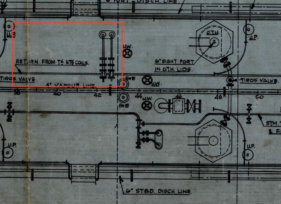
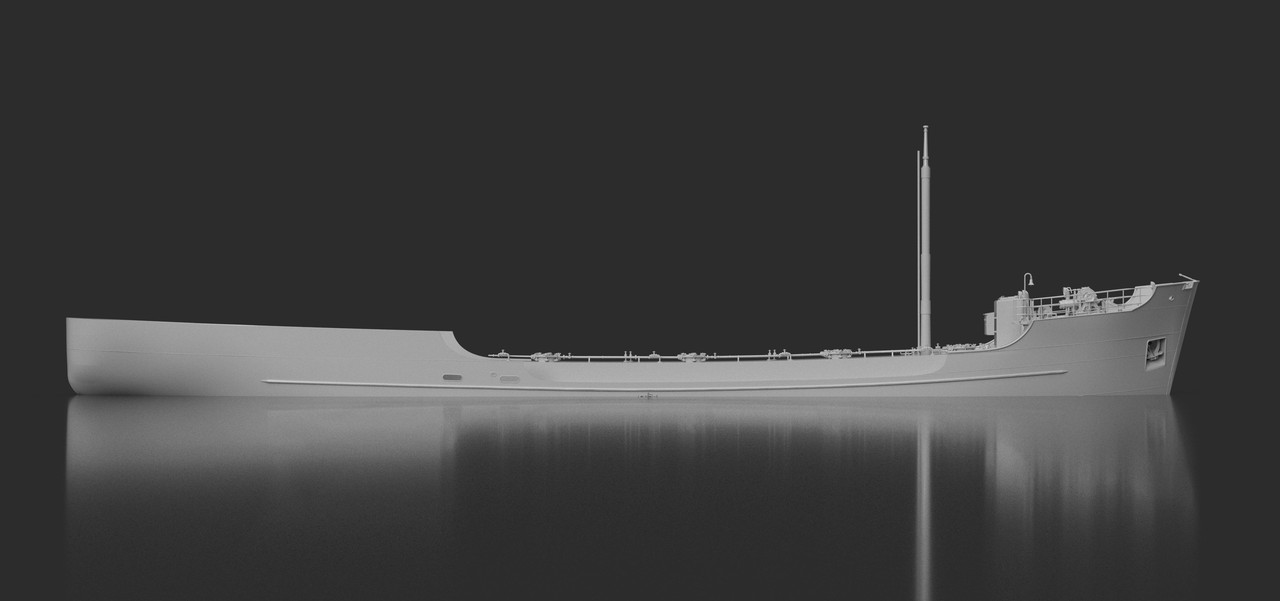
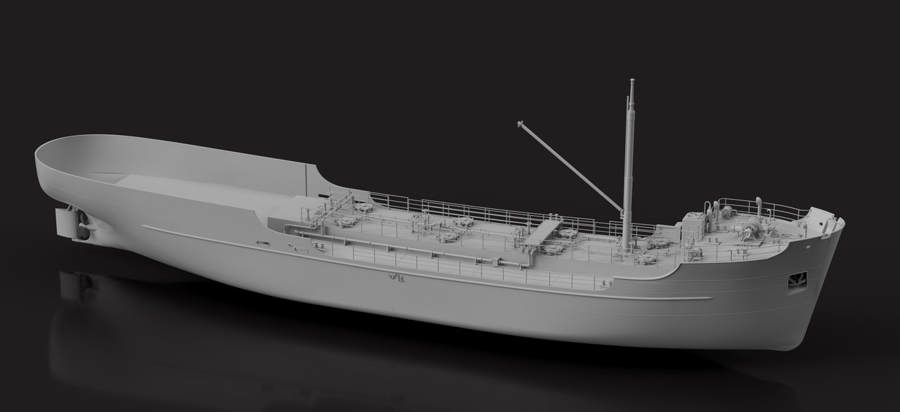
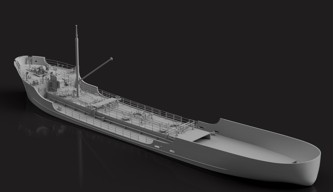
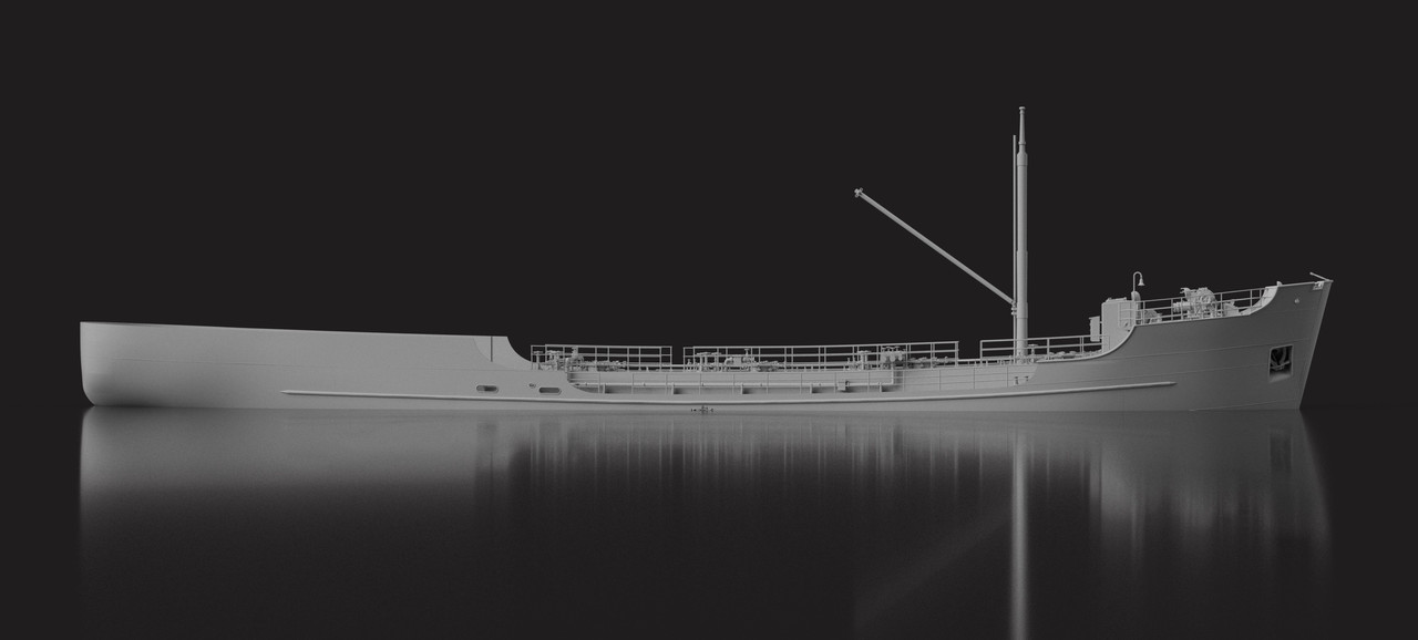
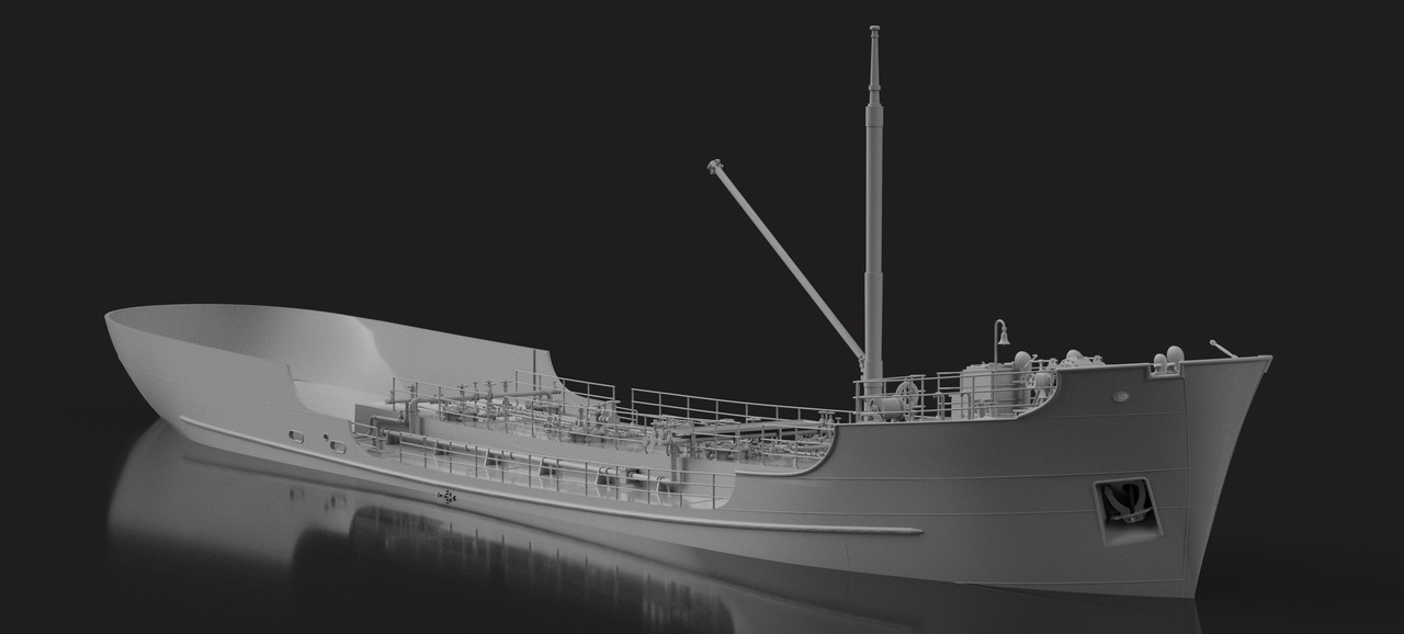
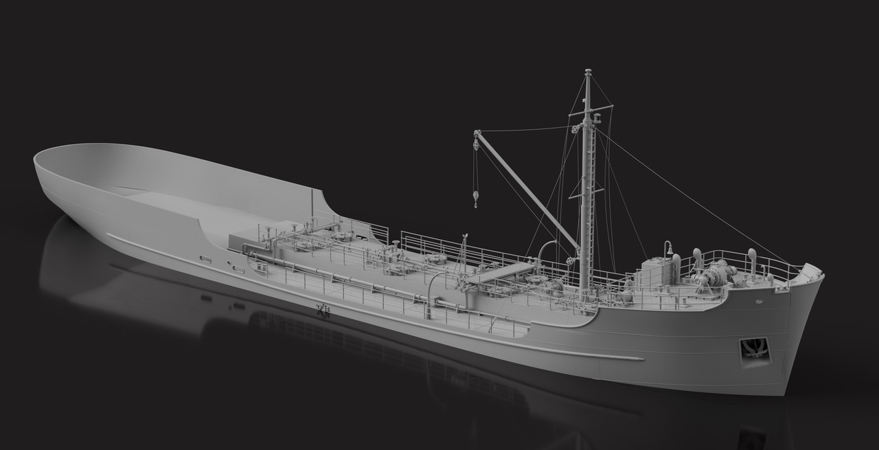
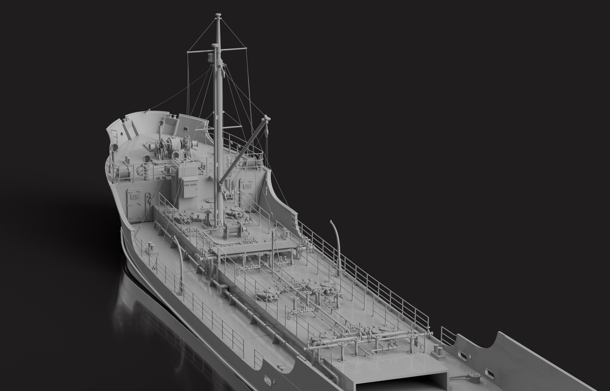
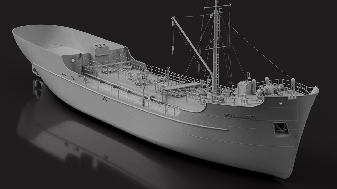
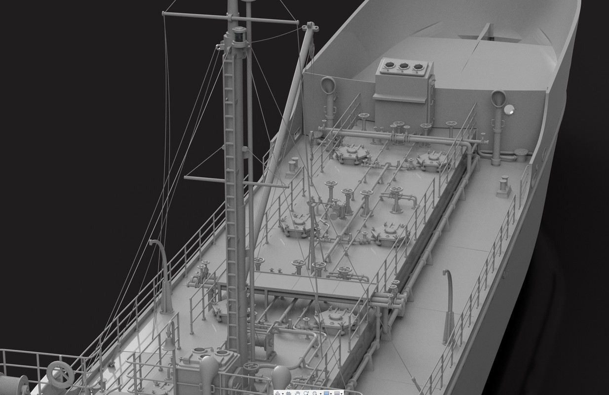
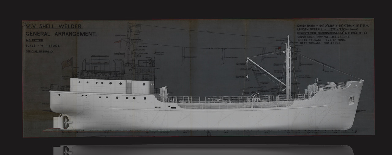
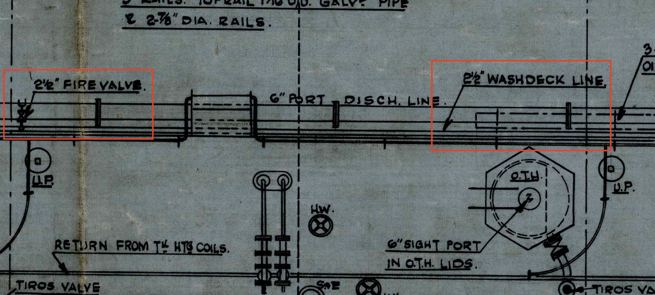
I wasn't talking about the fire hoses, which are generally 45 mm, any bigger is 70 mm, but about the size of the steel hose that runs from bow to stern, which is only 2 and a half inches.

Washdeck line = Main fire line, it's the same
Image

Nowadays, on merchant ships, the fire manifold that runs from bow to stern is much bigger, around 4 to 5 inches depending on the length of the ship, precisely to be able to supply several fire hoses at the same time and sometimes foam cannons.

Several hoses require a large flow upstream and a pressure of 10 bar. The larger diameter hoses are indeed difficult to handle, but sometimes necessary, you need 3 sailors.

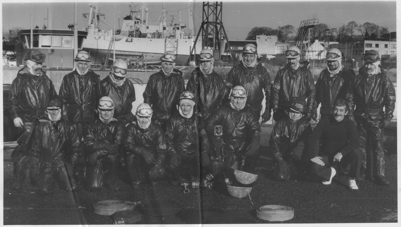
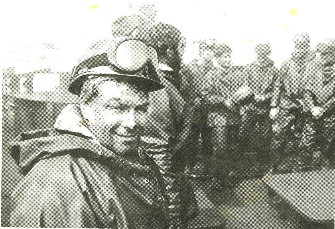
I did several fire training courses during my career, in the French Navy and the french Merchant Navy (compulsory, every 5 years), one week each time, sometimes in difficult conditions at the time.

My first fire training course for the merchant navy was in 1984, this site was opened in the port of Concarneau in Bretagne, France in 1983. It was run by the famous marine firefighters from Marseille.

I'm in the photo. It was exceptionally -15°C that week, in February, and there were ice cores in the lances.
We were also able to test the Helly Hansen waterproof survival suits in the harbour at this temperature.
Image

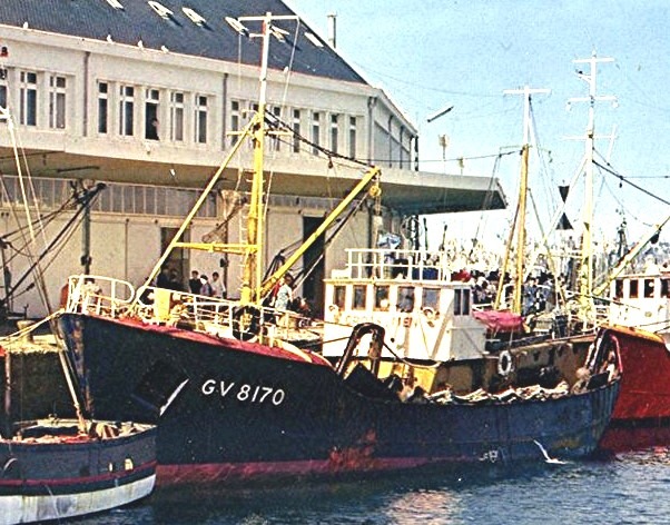
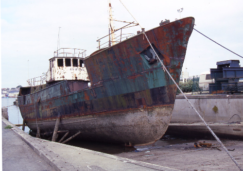
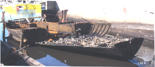
An old trawler of 28 meters was used for in situ fire drill in real conditions, in feb 1983, on the harbour floor, but surrounded by water,. It was a very good and very tough learning experience, in cramped premises on fire.

Image

Image

Image

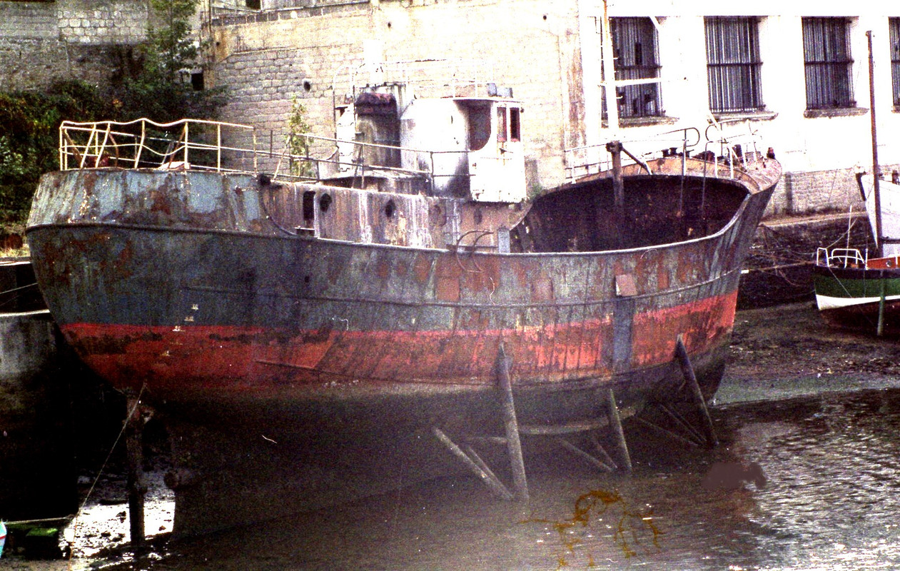
‘An Ifern’ means “The hell” in Breton language in France. :big_grin:

Image

Image

Image

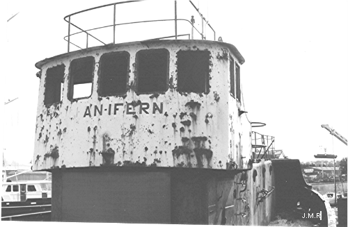
In 2000, she was scraped :

Image

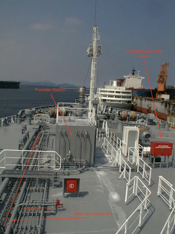
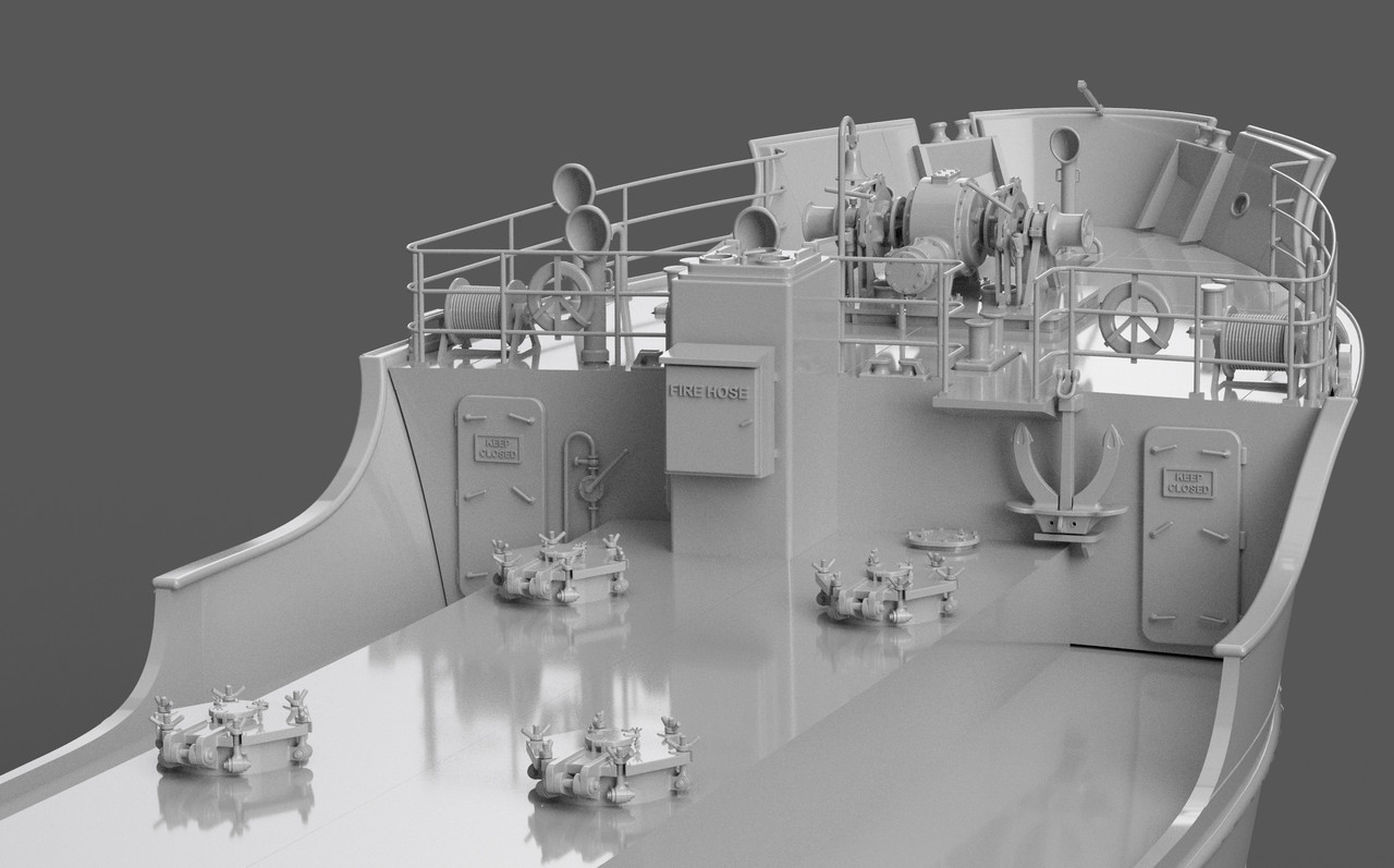
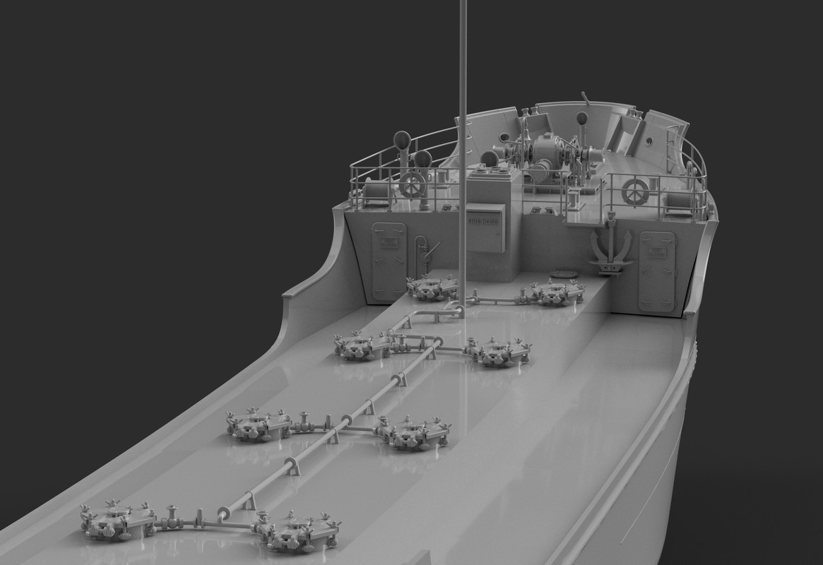
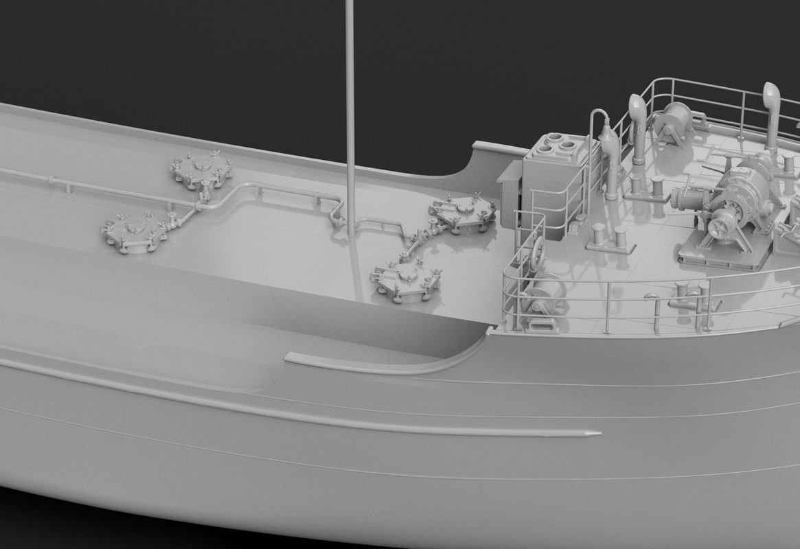
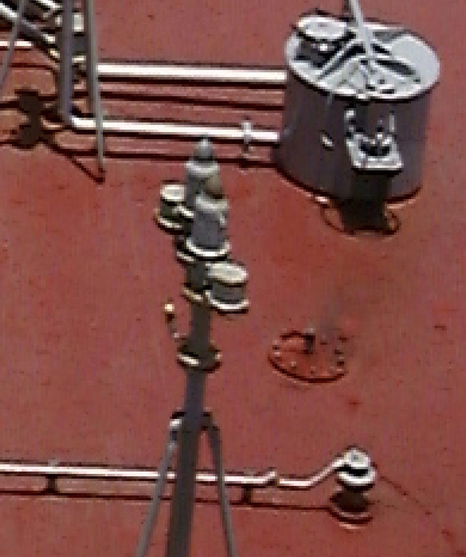
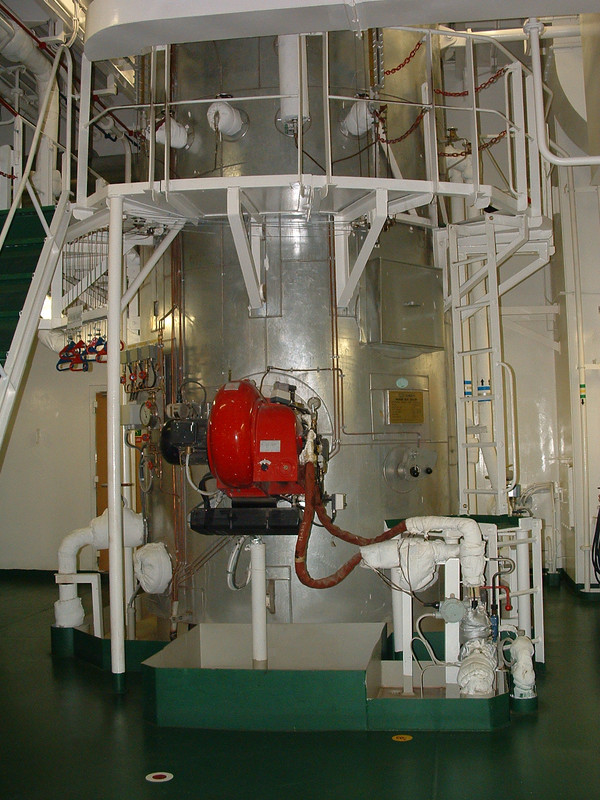
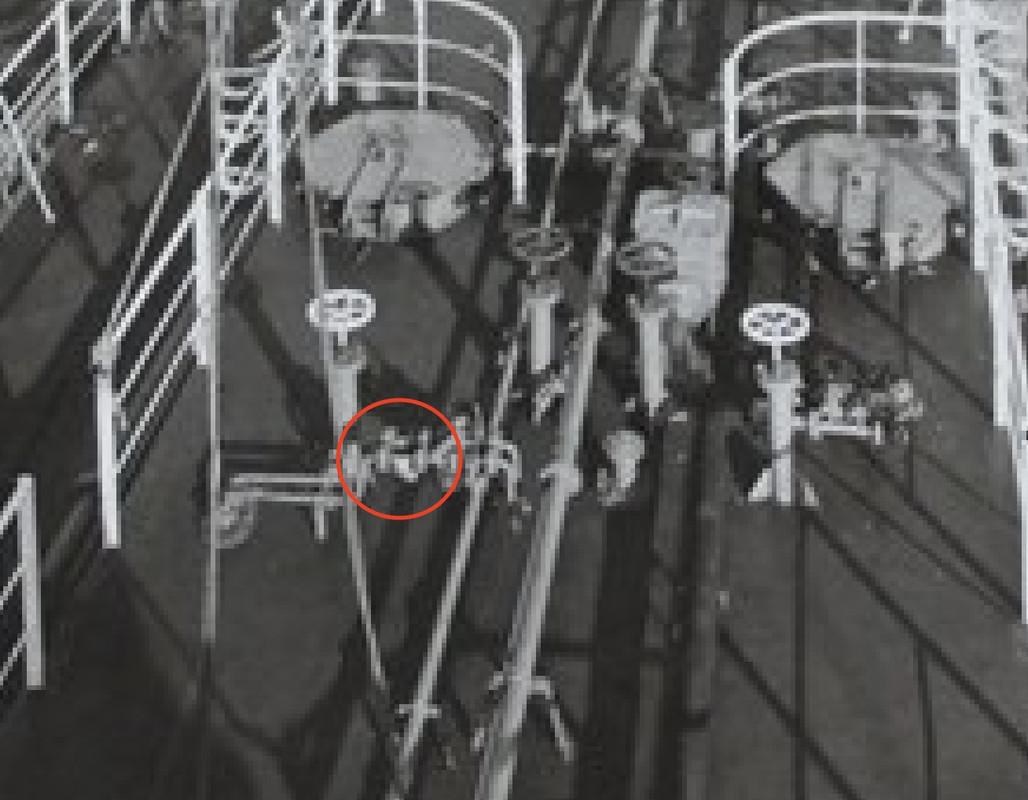
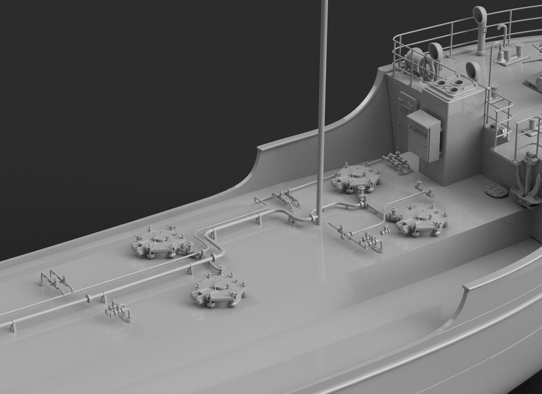
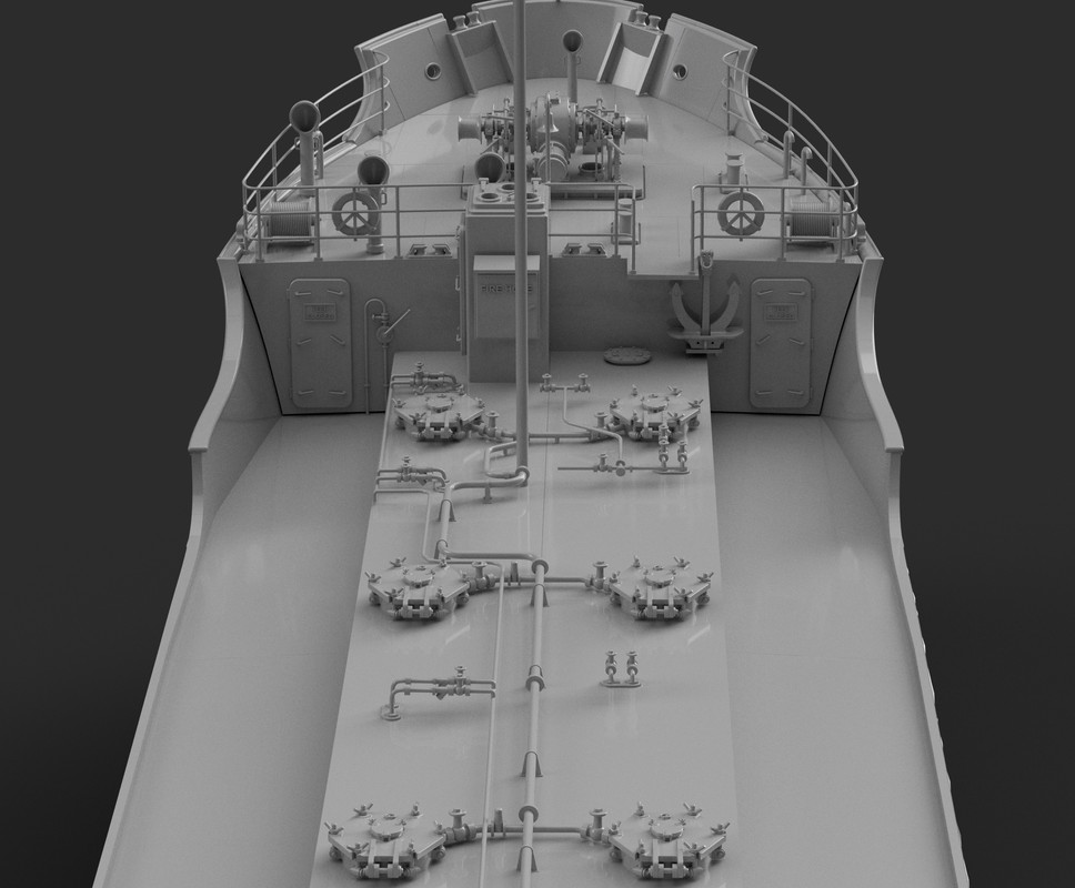
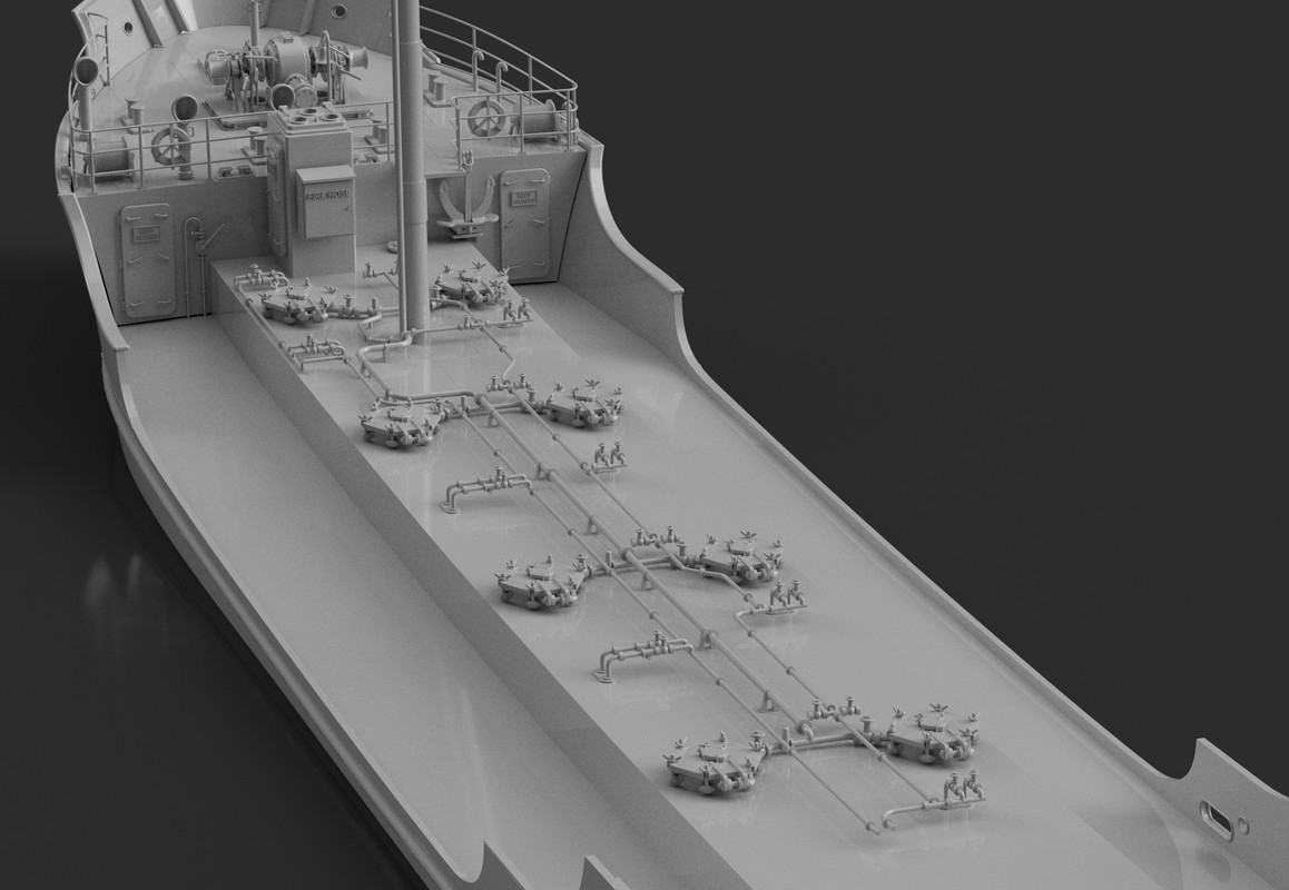
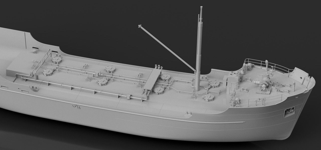
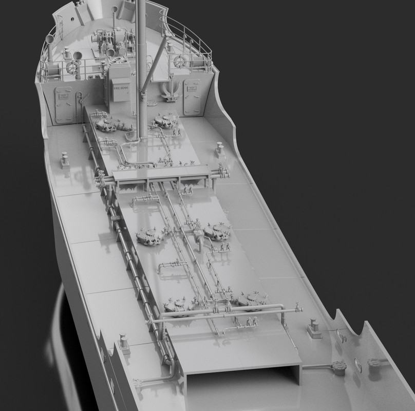
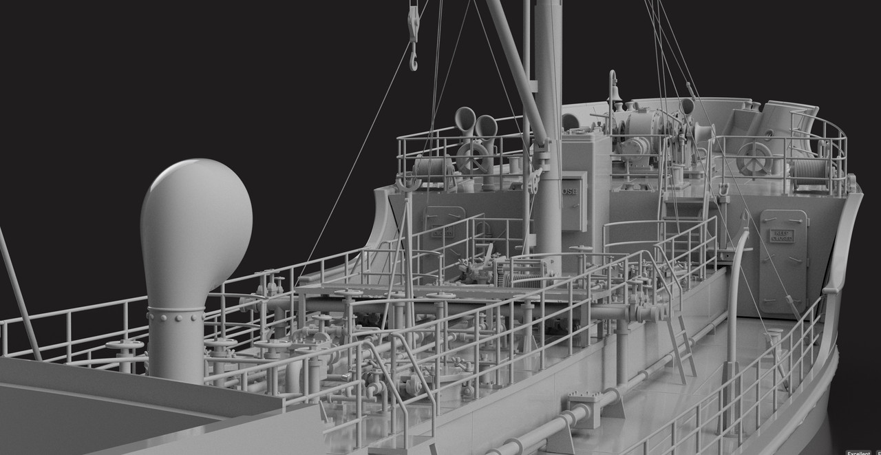
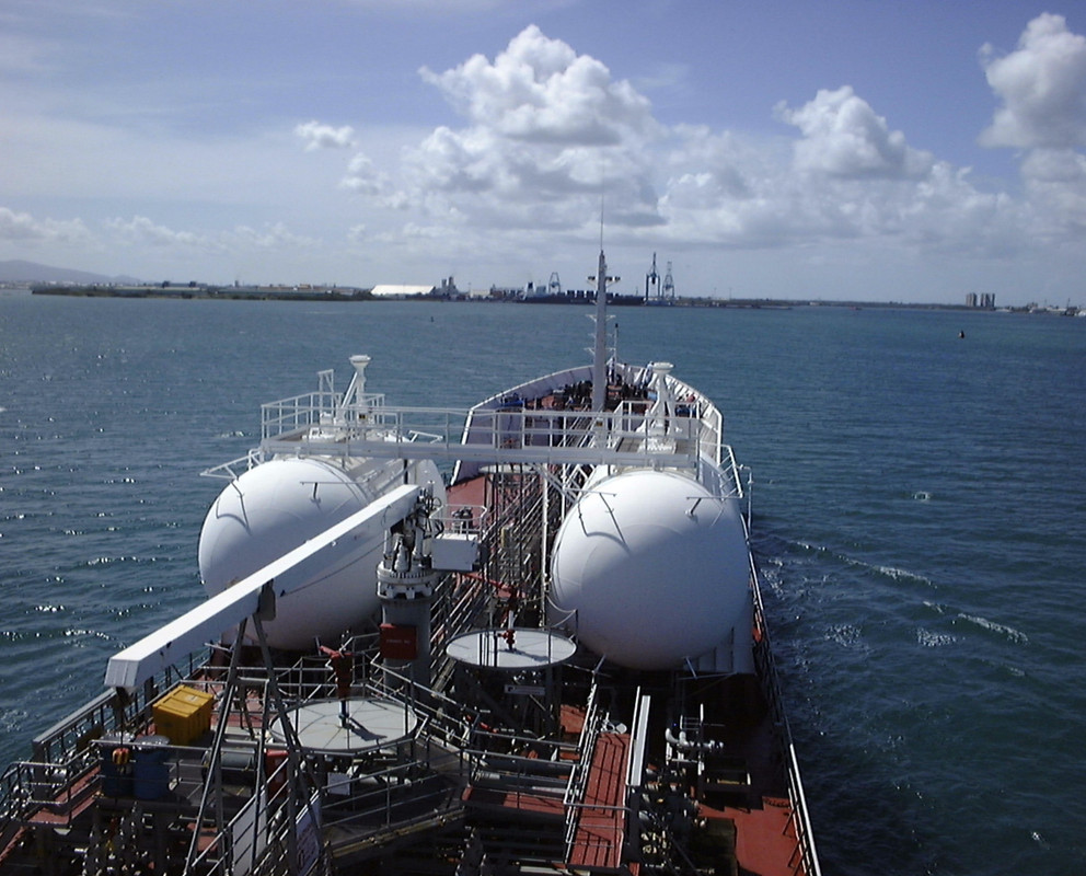
Here's a modern installation of 90's on a full-pressure gas ( 400 cubic meters) and oil tanker on which I sailed for 12 years, from new to sale.
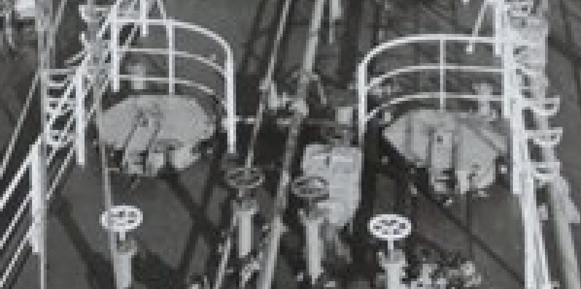
You can see the platforms with the physical foam lances.
The circuit is usually painted red, to give a clear view of the circuit and its isolation valves.
Fire drills are carried out every week.

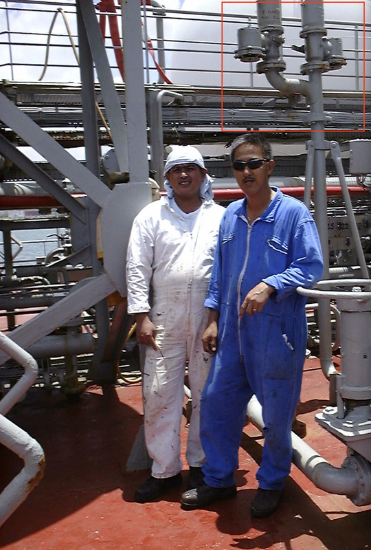
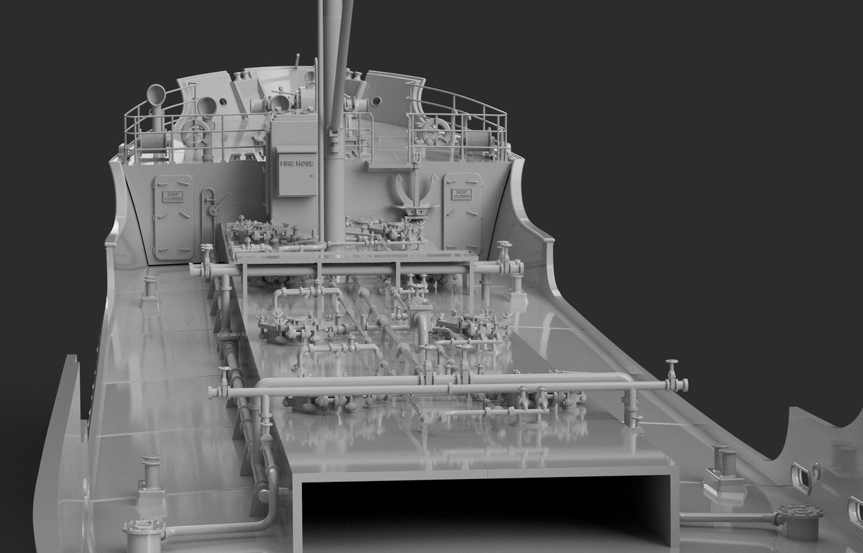
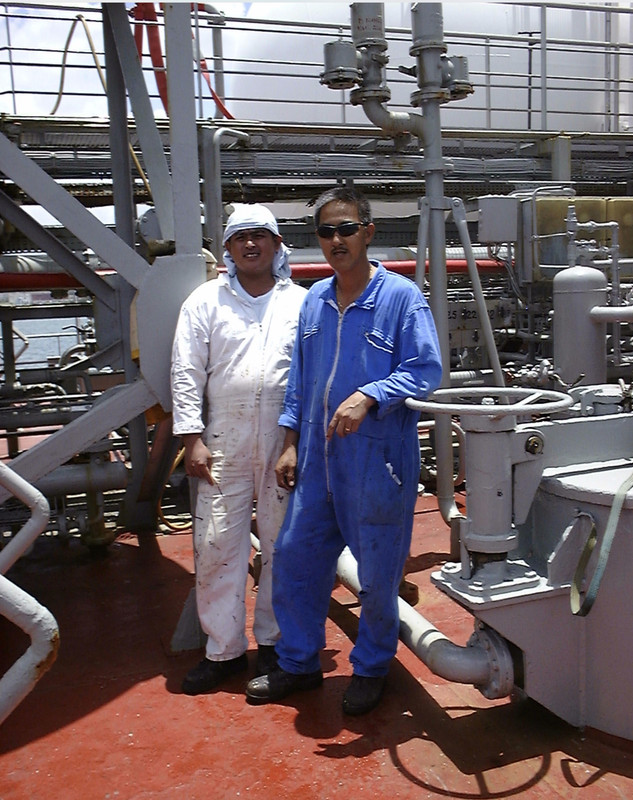
The red main fire hose can be seen behind the bosun and mate.
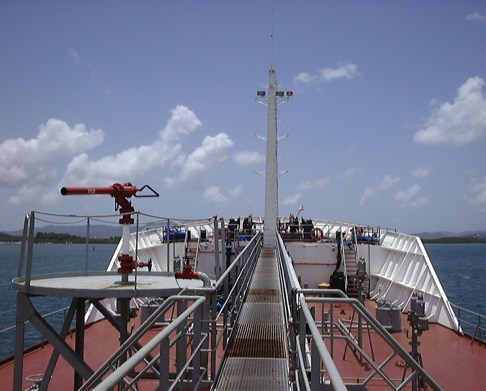
Above, you can see a 45 mm hose deployed, we're in a commercial loading or unloading operation, the hoses on the deck are unrolled and ready to be used.
This is one of the procedures that can make all the difference in the event of a fire: the quicker we intervene, the better our chances of extinguishing it.
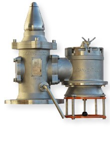
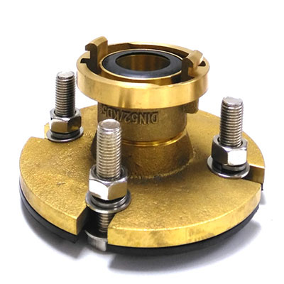
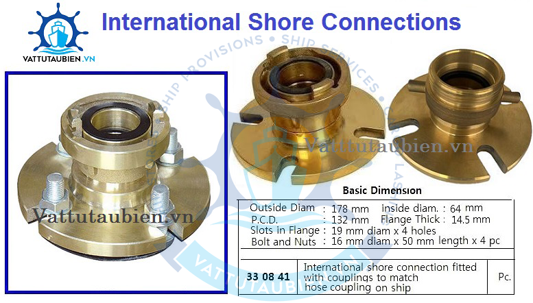
A plan of the fire circuit is available in a special box on the deck for the port fire brigade in the event of the ship being evacuated. A standard international connection flange is also available to connect the on-board fire circuit to that on the quayside in order to supply it in the event of a blackout.

Image

Different quick connections, depending on the country:
Image

Image

Image

Image

Image

Image

Image

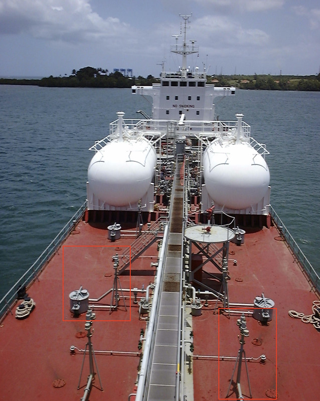
On a bigger ship, here a LPG gas carrier of 85 000 cubic meter, 225 meters long:

Personal picture:
Image

_________________
Pascal

•Battleship Bretagne 3D: https://vu.fr/FvCY
•SS Delphine 3D: https://vu.fr/NeuO
•SS Nomadic 3D: https://vu.fr/tAyL
•USS Nokomis 3D: https://vu.fr/kntC
•USS Pamanset 3D: https://vu.fr/jXGQ


Report this post
Top
 Profile  
Reply with quote  
PostPosted: Sun Aug 25, 2024 4:05 pm 
Offline
User avatar

Joined: Mon Jan 10, 2005 5:30 pm
Posts: 5556
Location: Nr Southampton England
Truly fascinating!!

thank you for this insight in 1:1 scale shipping ,

which often never concerns the ship model-maker

:thumbs_up_1: :thumbs_up_1: :thumbs_up_1: :thumbs_up_1:

Jim B :wave_1:

_________________
....I buy them at three times the speed I build 'em.... will I live long enough to empty my stash...?
http://www.modelshipgallery.com/gallery ... index.html

IPMS UK SIG (special interest group) www.finewaterline.com


Report this post
Top
 Profile  
Reply with quote  
PostPosted: Mon Aug 26, 2024 5:02 pm 
Offline
User avatar

Joined: Tue Sep 29, 2020 4:35 pm
Posts: 1881
Location: Bretagne, France
:thumbs_up_1:

Drawing of the superstructure front today.

Image

Image

Image

_________________
Pascal

•Battleship Bretagne 3D: https://vu.fr/FvCY
•SS Delphine 3D: https://vu.fr/NeuO
•SS Nomadic 3D: https://vu.fr/tAyL
•USS Nokomis 3D: https://vu.fr/kntC
•USS Pamanset 3D: https://vu.fr/jXGQ


Report this post
Top
 Profile  
Reply with quote  
PostPosted: Sun Sep 01, 2024 5:02 pm 
Offline
User avatar

Joined: Tue Sep 29, 2020 4:35 pm
Posts: 1881
Location: Bretagne, France
Today I was finally able to get back to drawing.

Added a plethora of details, corrected a few errors, rectified thanks to the photos.

The main tank deck and forecastle are now well advanced.

There are still a few details to be added, including manifold supports, fire valves, electrical wires and trunking on the foremast, and rigging for the cargo mast hoists. Reinforcement of the main deck bulwark and scuppers.

Image

Image

Image

_________________
Pascal

•Battleship Bretagne 3D: https://vu.fr/FvCY
•SS Delphine 3D: https://vu.fr/NeuO
•SS Nomadic 3D: https://vu.fr/tAyL
•USS Nokomis 3D: https://vu.fr/kntC
•USS Pamanset 3D: https://vu.fr/jXGQ


Report this post
Top
 Profile  
Reply with quote  
PostPosted: Thu Sep 05, 2024 4:17 pm 
Offline
User avatar

Joined: Tue Sep 29, 2020 4:35 pm
Posts: 1881
Location: Bretagne, France
I've started to draw the rear superstructures, to vary the pleasures... I'll come back to the drawing of the main deck later.

It's fairly easy to draw, but the difficulty here is anticipating how I'm going to 3D print the superstructures.

The design has its constraints, but so does the printing. So you have to make compromises. Sometimes you have to print prototypes to get good results in terms of quality and ease of physical assembly of the components. In this case, it's impossible to print everything from a single block, so you have to play with the possibilities offered by 3D resin printing.

So you need to think about this from the start of the design.

I'm going to repeat the method I used on the Delphine Yacht, embedding the superstructures in the deck, printing the bulkheads vertically, and printing the decks separately, also vertically, which split the parts in two:

viewtopic.php?f=13&t=349671&start=100

Image

Image

Image

The printer should be able to print the dunette deck in one piece, vertically, back to top.

Image

Image

Image

Image

Image

Image

_________________
Pascal

•Battleship Bretagne 3D: https://vu.fr/FvCY
•SS Delphine 3D: https://vu.fr/NeuO
•SS Nomadic 3D: https://vu.fr/tAyL
•USS Nokomis 3D: https://vu.fr/kntC
•USS Pamanset 3D: https://vu.fr/jXGQ


Report this post
Top
 Profile  
Reply with quote  
Display posts from previous:  Sort by  
Post new topic Reply to topic  [ 119 posts ]  Go to page Previous  1, 2, 3, 4, 5, 6  Next

All times are UTC - 6 hours [ DST ]


Who is online

Users browsing this forum: No registered users and 14 guests


You can post new topics in this forum
You can reply to topics in this forum
You cannot edit your posts in this forum
You cannot delete your posts in this forum
You cannot post attachments in this forum

Jump to:  
Powered by phpBB® Forum Software © phpBB Group