HMVS Cerberus in 1/96 scale - Completed 29/4/07

In progress online builds of Scratchbuilt ships of all scales. Remote Control and Static Display.

Moderators: MartinJQuinn, JIM BAUMANN, HMAS, Tiny69, Dave Wooley

User avatar
Edward Pinniger
Posts: 461
Joined: Wed Jan 18, 2006 1:05 pm
Location: UK

HMVS Cerberus in 1/96 scale - Completed 29/4/07

Post by Edward Pinniger »

I've temporarily postponed work on my scratchbuilt 1/200 HMS Belfast due to lack of references and in order to concentrate on finishing some other current project. However, I've decided to build another scratchbuilt ship in the meantime. I chose a subject which would be relatively simple and straightforward to build, and for which plenty of reference material is available. Originally I was going to build a small WW2 ship of some kind (minesweeper or gunboat) in 1/200, but ended up picking a late 19th-century ship.
I've always wanted to build a model of one of the really early "pre-predreadnought" armoured turret warships. I chose HMVS Cerberus due to the availability of a free paper/card kit of this subject and the fact that there's an entire website (http://www.cerberus.com.au) devoted to the ship with many photographs and drawings of the ship. It's also a bit smaller than similar Royal Navy ships like the Devastation and Dreadnought, hence the finished model will be more compact.

For more information on the history of this ship, see the above link. It's a turreted coastal defence monitor (often referred to as a breastwork monitor) built in the 1870s for the navy of Victoria (Australia), and is similar to British ships like HMS Devastation, though somewhat smaller. It was the first ship to use the classic "predreadnought" layout of two main turrets either side of a central armoured superstructure. The hull of the ship is currently rusting away as a breakwater, and its fate is currently uncertain.

The model is based on the Paper Shipwrights free paper model downloadable from http://www.papershipwright.freeserve.co.uk . I just printed out the plans and instructions, and enlarged the dimensions measured from the plans by 2.6 to build the ship at a scale of 1/96. I'm building the model to represent the ship during the late 1880s, with a shortened shelter deck, single mast and additional light guns for anti-torpedo boat defence, hence I've had to adapt the plans slightly.

I am intending to build this as a R/C model, using a fairly unconventional "low-budget" method (more on this later, if I can get it to work). This is the main reason for my choice of 1/96 scale - I would have preferred something like 1/150 for space reasons, but the motor/RC gear I have won't fit in a hull narrower than about 12cm.

It's constructed from styrene sheet of various gauges, Slaters textured sheet is used for the deck planking, and Evergreen-type styrene stock (strip, tube etc.) is used for most of the details. I may use white metal casting for some of the smaller deck fittings (bollards, capstans etc.) and the 6pdr and Nordenfelt guns.

The model is designed so that the major components of the ship are removable, which makes detailing much easier and should also allow the finished model to be dismantled for easier transportation. The superstructure lifts off the deck, the flying deck lifts off the superstructure, and both (rotating) turrets are removable.
Since the ship is almost symmetrical, but not quite, I've drawn large arrows on the hull to remind me which end is which!

Anyway, as this is a MUCH simpler ship than the Belfast and I have all the plans and reference material I need, it should be completed soon. I am still working on the Fletcher along with some smaller ships and a couple of aircraft models, but hopefully the Cerberus should be completed within a month or two, less than this if I'm lucky. I started work on this model on the 11th, so it has progressed from a pile of styrene sheet to its current form in only 5 days (with a couple of hours of work per day).

Here are the photos (apologies for the fairly poor quality)

Early stages (12/10/06)
Image
Image
Image

The model in its current state (15/10).
Image

The model in dismantled form.

Image

Close-up of the superstructure and turrets. A 1/96 figure (from the Revell USS Kearsarge) gives an idea of the ship's size. The conning tower (oval thing aft of the turret), charthouse and skylight assemblies are not yet complete or fixed to the deck, and the turrets currently have no roofs.
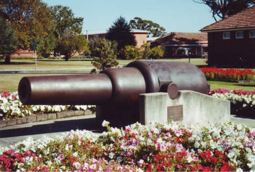
As you can see, the 11" turret guns are very simplified in form, just cylinders (this is what they should look like) - as only a short length of the barrel will be visible on the completed model, I really didn't think it was worth scratchbuilding accurately-shaped barrels and breech details.
Image

More updates soon hopefully. Today I painted the turret interiors, added more details to the charthouse, added the roofs to the heads and the bow/stern bulwarks to the hull, and started work on the skylight for the flying deck.

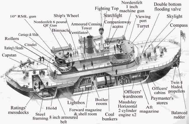
This is what it should look like when finished:
http://www.cerberus.com.au/labeleddrawing.jpg
Last edited by Edward Pinniger on Sun Apr 29, 2007 11:45 am, edited 1 time in total.
User avatar
Dave Wooley
Posts: 4131
Joined: Sat Jan 22, 2005 10:18 am
Location: Liverpool

Post by Dave Wooley »

Hi E Pinniger excellent choice of subject . Incidentally did you solve the problem concerning the davit arrangements ?
Dave Wooley
User avatar
ARH
Posts: 2557
Joined: Mon Jan 10, 2005 10:52 am
Location: Land of the Cheshire cat

Post by ARH »

Very nice, looking forward to more work, thanks for posting. ARH :jump_1: :jump_1: :thumbs_up_1:
Simple but effective.
User avatar
JIM BAUMANN
Posts: 5682
Joined: Mon Jan 10, 2005 5:30 pm
Location: Nr Southampton England

Post by JIM BAUMANN »

Ok thats veryneat!

I just ordered the cerebus(the complex version) from Papershipwright--but asked him to re-print it to 1/350

I plan on building a hybrid--part card part solids-and using much of my spare PE fro the finer parts

I shall be following your build with interest-along with all the other fine scratchers here!!

JIM B :wave_1:
....I buy them at three times the speed I build 'em.... will I live long enough to empty my stash...?
http://www.modelshipgallery.com/gallery ... index.html

IPMS UK SIG (special interest group) www.finewaterline.com
User avatar
Jefgte
Posts: 542
Joined: Fri Aug 26, 2005 6:53 am
Location: France

Post by Jefgte »

Nice model to come EP :lol_spit_1:
Original & no frequent Battleship to come.


Jef :thumbs_up_1:
Current 1/700 WL
HMS Repulse
TommyL
Posts: 292
Joined: Mon Sep 19, 2005 8:59 pm

Post by TommyL »

I just checked out Paper Shipwrights site and it looks like they have some very interesting subjects to build.

Ill have to make a mental note to check in on this every now and then.

TommyL.
User avatar
Edward Pinniger
Posts: 461
Joined: Wed Jan 18, 2006 1:05 pm
Location: UK

Post by Edward Pinniger »

Thanks for the replies. Still making good progress, currently I'm working on the flying deck details (skylights, vents, conning tower, charthouse etc.) - will post some more pics tomorrow or Wednesday.
Dave Wooley wrote:Hi E Pinniger excellent choice of subject . Incidentally did you solve the problem concerning the davit arrangements ?
Dave Wooley
I haven't got as far as the davits yet - what is the problem with them?
Currently I'm trying to think of an easy way to drill the 100+ perforation holes needed in the flying deck support girders!
User avatar
Dave Wooley
Posts: 4131
Joined: Sat Jan 22, 2005 10:18 am
Location: Liverpool

Post by Dave Wooley »

Hi E Pinniger When Dave Abbott built his Cerberus at 1:196 there was some dispute as to how the davits functioned from the position above the main deck . A question still to be answered. I've included a picture of Dave's model showing the davit arrangement.
Image
Dave Wooley
RickF
Posts: 128
Joined: Fri Oct 14, 2005 4:52 pm
Location: Norfolk, UK

Post by RickF »

I believe that the davits are pivotted at the base and wound in and out by cable drums under the flying deck. They appear to be pulled into crutches on the flying deck.

Rick
Image
Black, white and buff - not grey!
User avatar
Dave Wooley
Posts: 4131
Joined: Sat Jan 22, 2005 10:18 am
Location: Liverpool

Post by Dave Wooley »

It appears on the drawing that the davit is fixed to the flying deck as Dave Abbott's model shows. But the question is still the same . The boat have to be lowered some how. There is a picture of one of the boats being lowered onto the main deck and then swung out.
Dave Wooley
User avatar
JIM BAUMANN
Posts: 5682
Joined: Mon Jan 10, 2005 5:30 pm
Location: Nr Southampton England

Post by JIM BAUMANN »

Is it possible the davits were used merely for lowering the boats--and that getting them outboard of the hull was achieved via skid planks-lashed temporarily by the crew?

I have seen something similar on a russina monitor-the name escapes me... but the boat is lowered via the davit and the boat simly slides outboard via the skids

Cheers

JIM B
....I buy them at three times the speed I build 'em.... will I live long enough to empty my stash...?
http://www.modelshipgallery.com/gallery ... index.html

IPMS UK SIG (special interest group) www.finewaterline.com
RickF
Posts: 128
Joined: Fri Oct 14, 2005 4:52 pm
Location: Norfolk, UK

Post by RickF »

The davits seem to have changed when the flying deck was shortened, but several pictures on http://www.cerberus.com.au/image_library.html# show them extended outwards. Some of the as fitted plans available on the State Library of Victoria's website appear to show the cable drums under the full length flying deck.

Rick
Image
Black, white and buff - not grey!
Pieter
Posts: 1604
Joined: Sat Sep 17, 2005 9:19 am

Post by Pieter »

This problems seems to have been realised by the designer (Edward Reed) too. If you look at pictures of the Cyclops class , which were almost sister ships of Cerberus until the breastworks were changed on the Cyclops class in 1885, the davits were much lower and attached to the breastworks sides. The two largest boats were put on a rack on the flying deck with a crane mast just before them. The main difference between Cerberus and Cylops is off course that Cerberus needed to have a built up temporary superstructure for her crossing to Australia so having boats and davits in the position as on Cyclops was not an option. Cyclops only needed to reach Cherbourg on a calm day.
Interestingly Reed went for a totally different solution in HMS Devastation and Thunderer.
Pictures of the Cyclops class can be found at
http://www.battleships-cruisers.co.uk/c ... %20Cyclops
RickF
Posts: 128
Joined: Fri Oct 14, 2005 4:52 pm
Location: Norfolk, UK

Post by RickF »

Here are a couple of photos courtesy of the "Save the Cerberus" website.

The first shows the foot of a davit (bottom left), clearly showing the hinge or pivot.

The second shows the later type davits extended for launching. These cranked davits apparently replace the earlier straight ones when the flying deck was shortened. The fore and aft sets of davits were removed from the breastwork at this time and relocated (I think) on the main deck.

As regards the boat skids Jim mentioned, the centre set of davits on the flying deck was fitted with them, so possibly these davits were not pivotted. The skids also remained in place after the flying deck was shortened and the other davits were moved. At this time the centre set must have been fitted with pivots, as the photo below shows.

Image

Image

Regards

Rick
Image
Black, white and buff - not grey!
User avatar
Dave Wooley
Posts: 4131
Joined: Sat Jan 22, 2005 10:18 am
Location: Liverpool

Post by Dave Wooley »

Hi Rick F Yes that confims it . The photos contain a wealth of pertinent detail .
Dave Wooley
User avatar
Edward Pinniger
Posts: 461
Joined: Wed Jan 18, 2006 1:05 pm
Location: UK

Post by Edward Pinniger »

The model as of 17/10 (yesterday). Lots more details on the flying deck, plus roofs on the turrets and work started on the deck skylights. Still a lot more work to do, but it's definitely starting to look like the Cerberus!
The engine air intake (between the conning tower and charthouse) will soon be replaced with a cowl vent - unfortunately I built and fitted this part before discovering it wasn't accurate for the ship's 1880s configuration.

Image
Image
Image
Last edited by Edward Pinniger on Wed Oct 18, 2006 10:18 am, edited 1 time in total.
User avatar
Dave Wooley
Posts: 4131
Joined: Sat Jan 22, 2005 10:18 am
Location: Liverpool

Post by Dave Wooley »

Super piece of work and as you say the model is starting to take on the appearance of Cerberus . A good choice of subject and well done .
Dave Wooley
RickF
Posts: 128
Joined: Fri Oct 14, 2005 4:52 pm
Location: Norfolk, UK

Post by RickF »

Yes Dave, but I'm still unsure about the "original" davits. Were they fixed? It seems a strange way of getting a boat into the water, but Pieter and Jim may be right. I guess the centre set must have been fixed, as skids were provided, but what about the fore and aft sets? Is the picture you mentioned of a boat being lowered to the deck using the old or new davits?

In the photograph below you can see the hoists leading to the cable reels under the flying deck that I mentioned earlier. Did these also extend the davits?

Image


Rick
Image
Black, white and buff - not grey!
User avatar
kennylibben
Posts: 1065
Joined: Tue Jan 11, 2005 7:25 am
Location: I live in Off-Topic...
Contact:

Post by kennylibben »

holy crap this is a fast build!

and i love it too!
It's not who you are, but what you do that defines you.
User avatar
Dave Wooley
Posts: 4131
Joined: Sat Jan 22, 2005 10:18 am
Location: Liverpool

Post by Dave Wooley »

My apologies to E Pinnger for comming in like this on his super build. Only the problem of how the davits functioned has gone on for years and this model built by Dave Abbott 10 years ago has been one of the few around that can be referenced with some accuracy . Rick I see what you mean regarding the picture and the position of those cable reels. The picture I recall shows the boat lowered onto the main deck and man handled over the side. This may have been quite feasible because of the low freeboard. But on her voyage out to Australia the sides were extended up well above the main deck, which would have made it impossible to lower and launch the boats from the that deck. Although these pictures have been seen on this site before it�s worth investigating how these davits functioned and Dave Abbott's model, which was built from a set of original drawings or at least copies has perhaps generated more questions than answers .
There doesn't seem to be any purchases for lowering these davits and so this may well have been the original configuration . It may be that modifications to the davits were undertaken just prior to the ship leaving for Australia .to allow the davits to swing out and clear of the raised sides
Once again It's really good to see another modeller taking up the challenge and building this unusual and interesting ship, keep the pictures of your model comming
Image
Post Reply

Return to “Online Scratchbuild Projects”