Thanks, gentlement

************************************
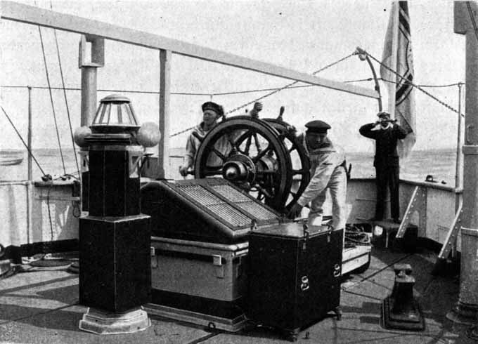
The MastThese boats initially had a very simple one-piece mast for signalling purposes. At a later stage, a more complex version with a topgallant mast and cross-tree was installed to allow for a better spread of signal flags and the cones that indicated the rudder direction to facilitate flotilla manoeuvres. However, the model will be fitted with the simple mast only.
The mast itself was turned from a 1.5 mm steel-rod with a shoulder to accommodate the four shrouds and hangers for the signal halliard blocks. The information is rather scarce with only the earliest picture of S.M.S. WESPE showing the whole mast and the lithographs showing the lower part. The height had to be estimated from the photograph, while the lower diameter could be taken from the lithograph. The belaying pins for the signal halliards are set into a wooden shelf, rather than into the spider band. This wooden shelf was fashioned from a tiny piece of bakelite paper into which the appropriate holes were drilled before.
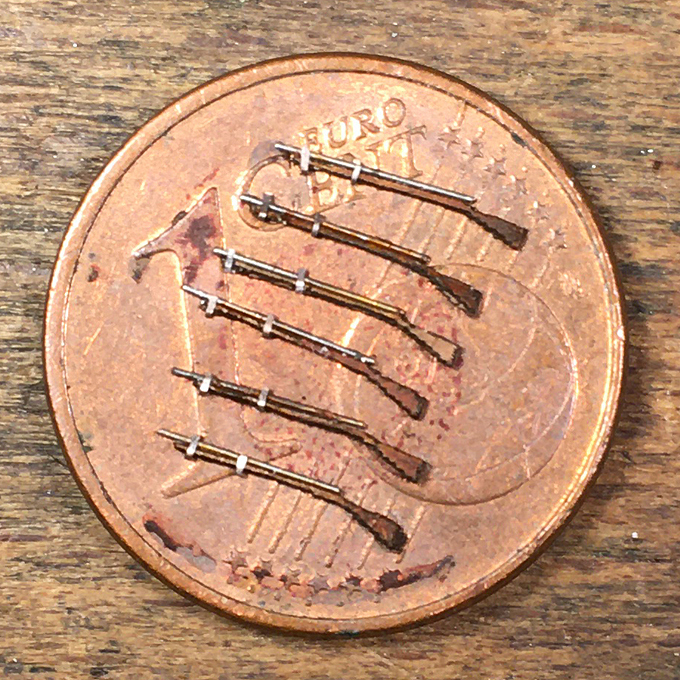
Belaying pins of 2 mm length and 0.2 diameter are a modelling challenge. A first attempt using lengths of wire and drops of white glue to represent the handles did not produce consistent and satisfactory result. Therefore, I decided to attempt to make them the ‘proper’ way, i.e. to turn them.
After a couple of failures (though the first two attempts went well), I arrived at a procedure that produced consistent results with a low failure rate. The key is to do the turning in small steps to minise cutting forces, having a sharp tool, set to just a tad below centre-height. The material used was 1 mm mild steel-rod because the brass I have available would have been far too soft for such tiny pieces. Although the belaying pins are a bit oversized for flag-halliards, making the pins was a bit of a proof of concept with my follow-on project in mind, where I will need quite a number of such small ones.
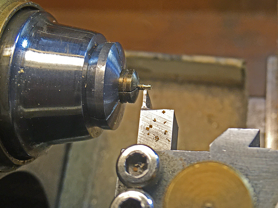
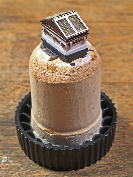
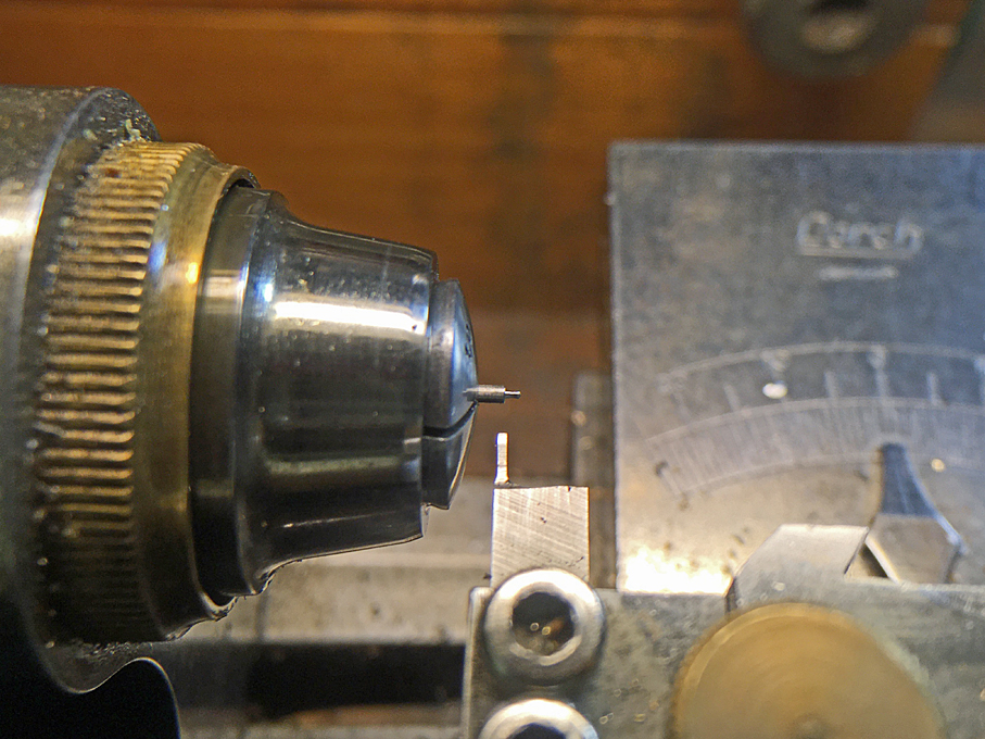
In a first step, the 1 mm diameter was reduced to 0.4 mm over a distance of 0.8 mm.
 1st step in turning micro-belaying pins: roughing out the handle
The handle then was shaped using a 1 mm mouse-tail and a tiny flat file:
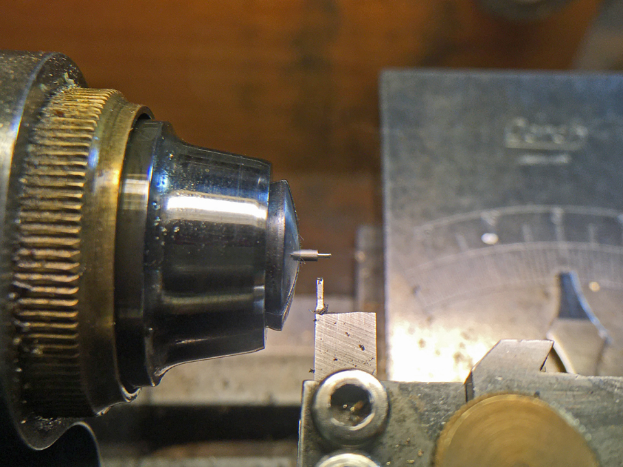
 2nd step in turning micro-belaying pins: shaping the handle with files
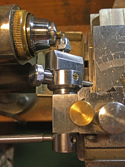
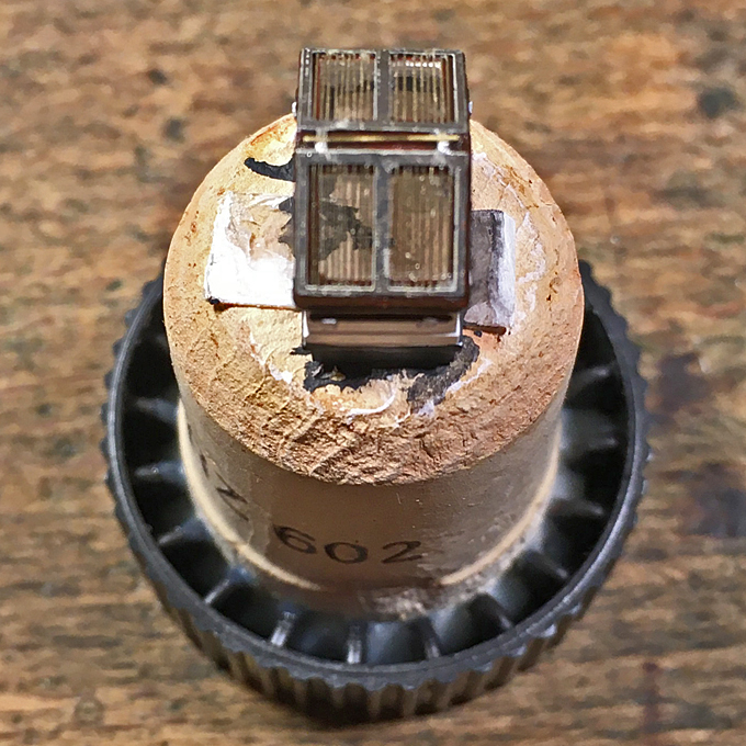
Then the diameter below the handle was cautiously reduced to 0.2 mm. The first cut here is quite critical, as the square cutting tool cuts over its whole width of 0.4 mm.
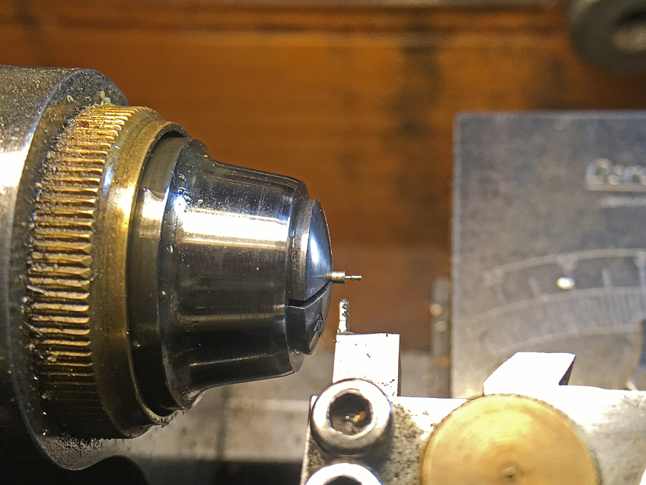 3rd step in turning micro-belaying pins: reducing the diameter of the shaft to 0.2 mm
In several 0.2 mm steps one then works towards the target length of 2 mm.
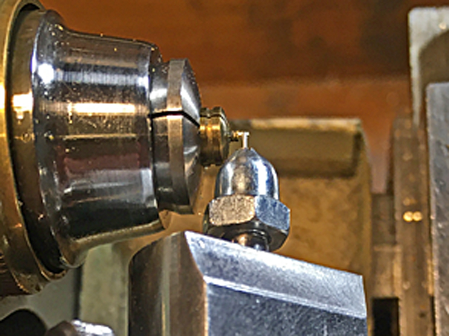
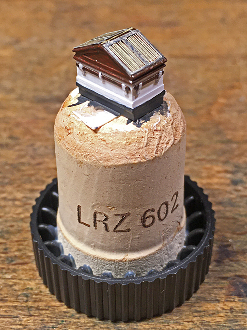
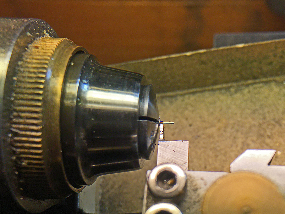 Final step in turning micro-belaying pins: reducing the diameter of the shaft to 0.2 mm
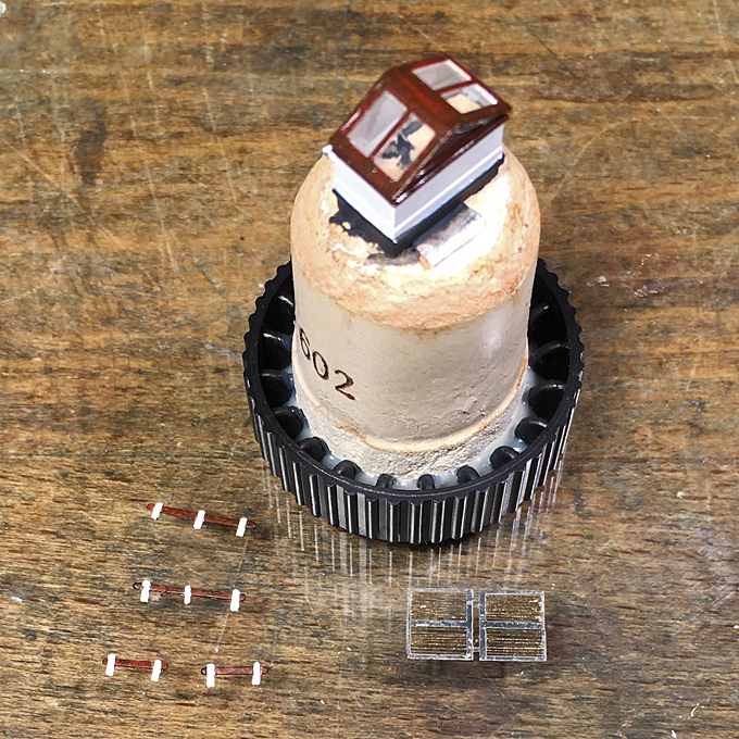
When trying to reduce the diameter below 0.2 mm, the finished belaying pin usually shears of cleanly from the stock. The pins then were chemically blackened.
The mast was given a base-coat of Vallejo 71.033 Yellow Ochre, a wash of Schmincke 28610 Ochre, and a very light glazing of Vallejo 70.956 Clear Orange. Once the blackened belaying-pins had been inserted the whole assembly was given a light coat of a mixture of Vallejo satin and gloss varnish to make the mast resemble oiled wood. The shoulder, were the shrouds rest probably had been protected by a copper sheathing and this was imitated by paint.
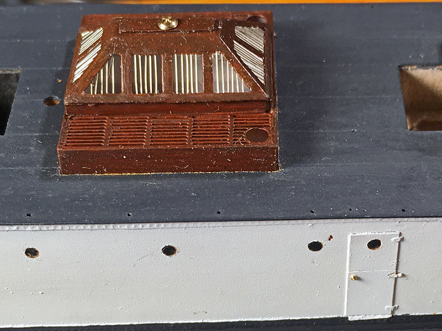
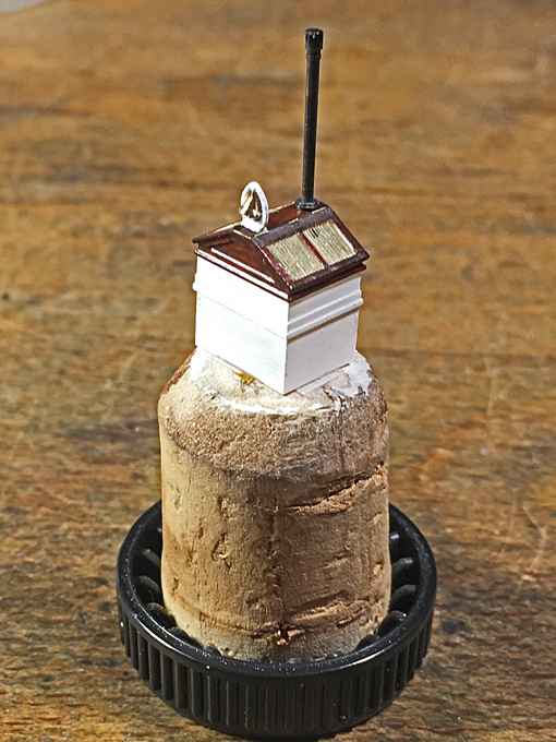
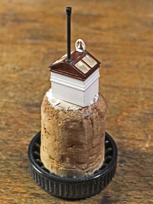
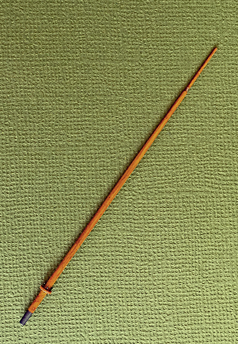 The finished mast
The shrouds were probably made from galvanized steel rope and need to be served in the area where they attach to the mast. I still have to work out a good way to imitate this in 1:160 scale and probably need to build the serving machine first that I had planned to make for a long time.
To be continued ....


 Shellac can be adjusted to any desired viscosity by adding more or less alcohol and can redisolved any time. It has been used as adhesive by watchmakers and jewellers for centuries, and of course as varnish by cabinet- and instrument-makers.