No can never have enough tools and machines

**********************************************************
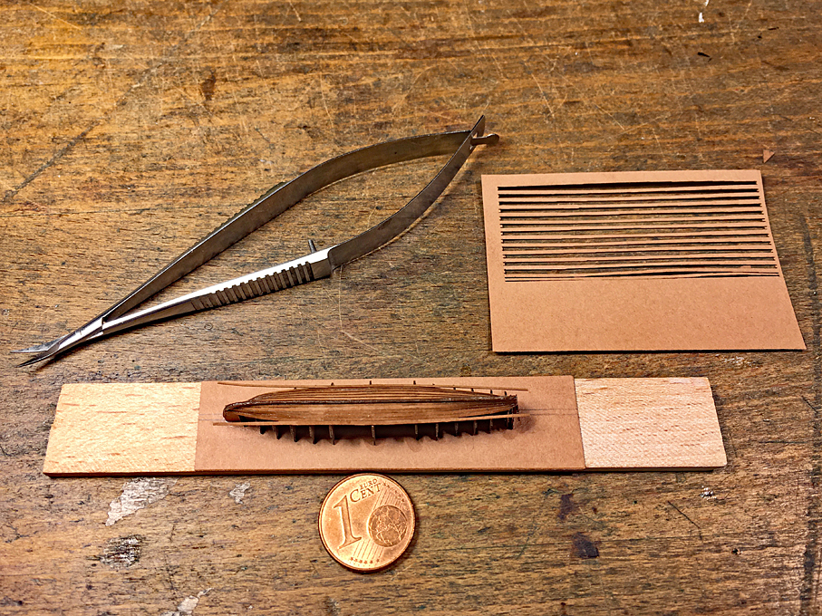
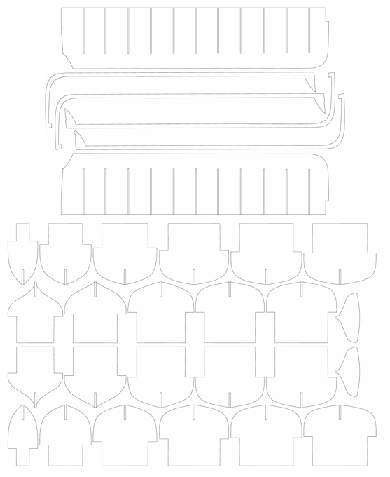
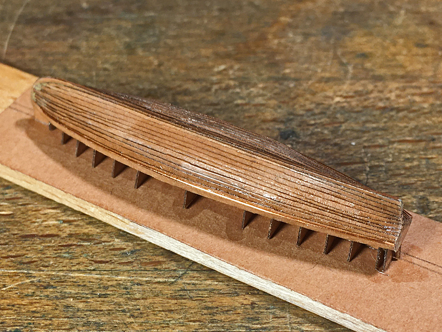
Work on the Gig continuedThe planking progressed reasonably well, but I actually needed to more strakes per side to be able to go up to the sheer-line. Not good for strake counters … I attribute this to the wider overlap needed than expected. This was particularly the case, where there is a significant angle between planks, e.g. at the turn of the bilge. For the other boats, I will have to cut the planks a bit wider.
 Planking completed
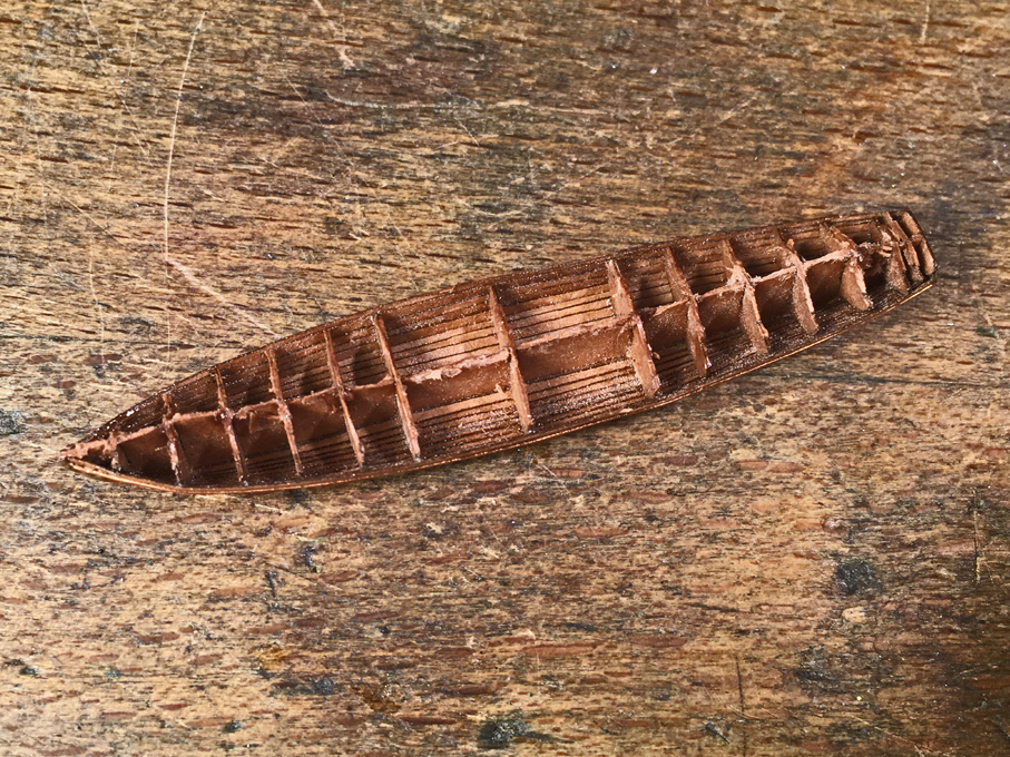
A few conclusions from this exercise for the other boats:
- Cut the planks tapered only on one side, as they can edge-bend, when soaked in varnish
- Cut the planks for 30 to 40% overlap not 20% as done in this example; this gives more flexibility to adjust the planks
- Do not try to imitate full-scale practice by running the planks into a rabbet on the stem, rather attach the outer stem and keel-piece after the planking is complete and has been trimmed down to the rabbet line.
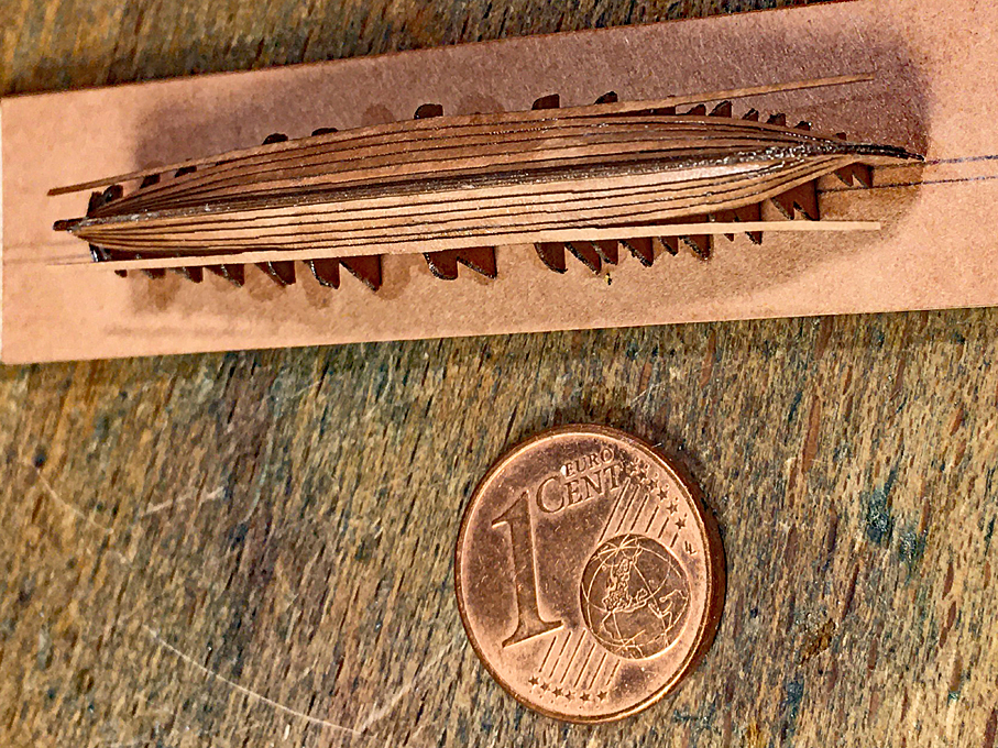
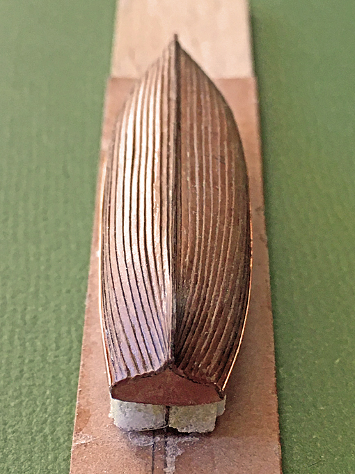
 Planking completed
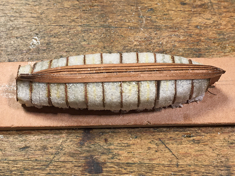
The planking now was cleaned up and the excess at the transom trimmed back. I tried to sand the jaggy edges a bit, but that did not work very well on the paper. However, in the varnished state it is not very visible. One has to see, when it is painted.
The hull was lightly rubbed down with fine steel wool to smooth the surface. Then some spots, where touched up with some putty.
 Rubbing strake from 0.2 mm copper-wire installed
According to the prototype cross-section, there was a rubbing strake added to the top-strake. It was ‘faked’ by attaching a 0.2. copper-wire below the last strake.
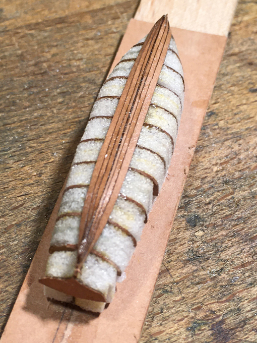
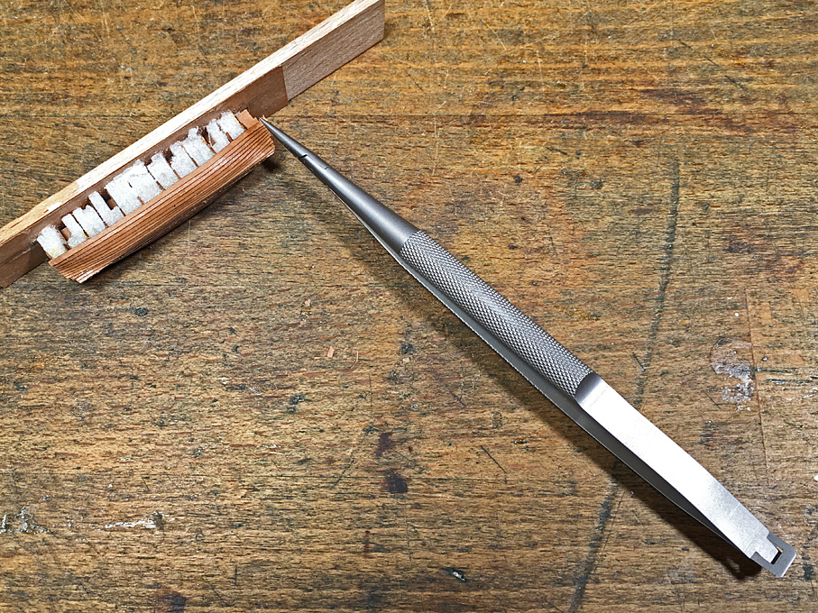
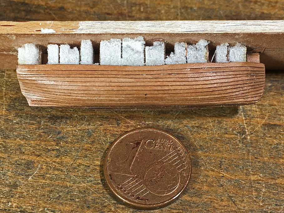
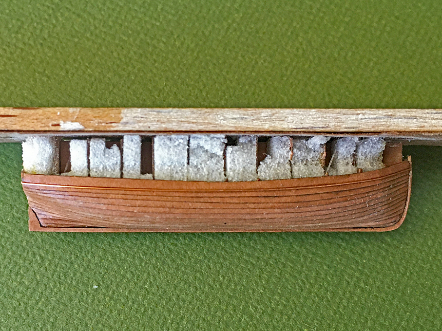
Now the boat was ready to be cut from the base. The bulkheads were cut down and the keel-piece trimmed to a line that would be followed by the tarpaulin cover.
There is a hoisting chain fore and aft to which the falls of the boat-davits will be hooked, As only the rop ring will be protruding from the boat-cover, this chain was simulated by a drilled together piece of tinned 0.2 mm coper-wire. It was hooked into a bulkhead and glued down with varnish.
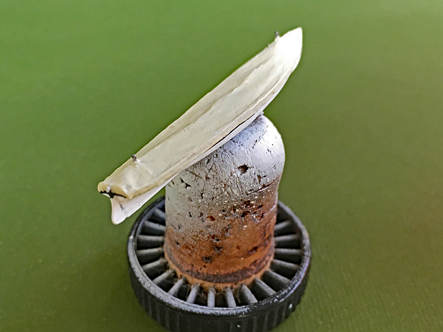
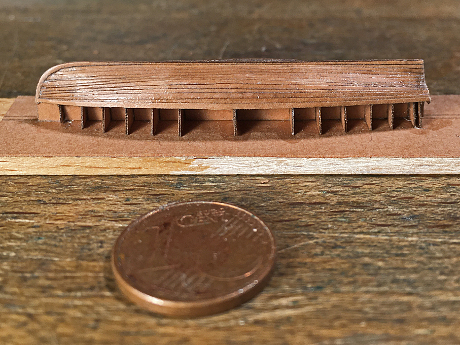
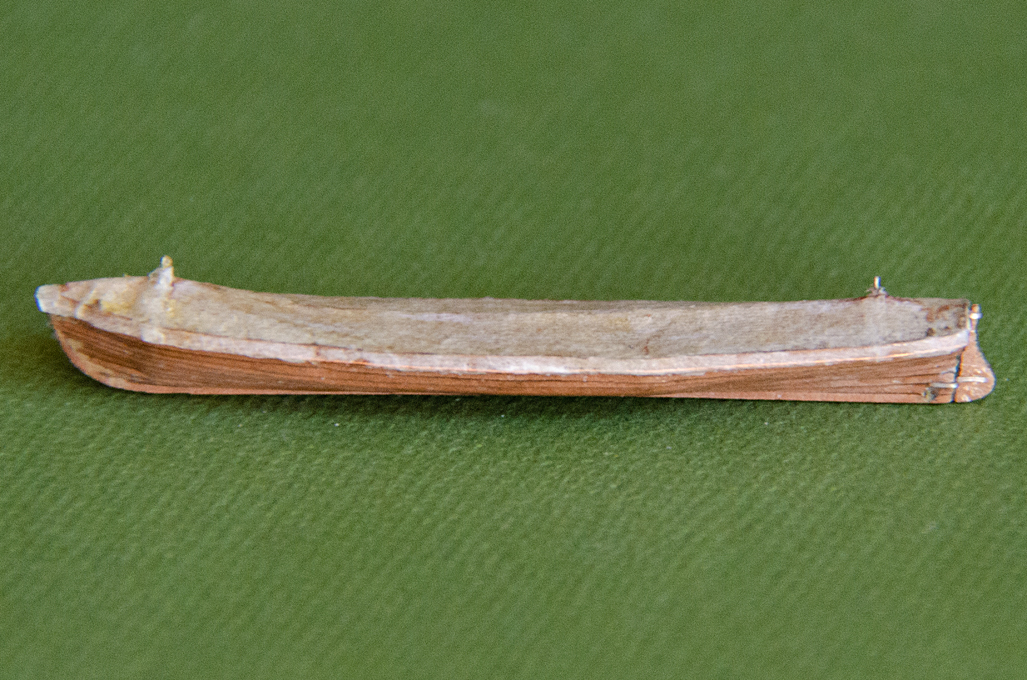
 Boat cut free from the building base
Most modellers seem to show the boats open, but most historical photographs show them covered. The design of the cover seems to vary a bit and I could not find information about this. Some photographs show the cover going down over half of the sides of the boat, with ropes apparently zig-zagging down to the keel and back up on the other side. Others seem to show a line going through a hollow seam to pull it tight around the boat. I opted for the latter to show more of the planking and the (later) paintwork.
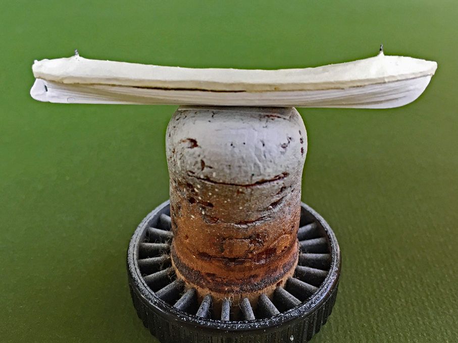
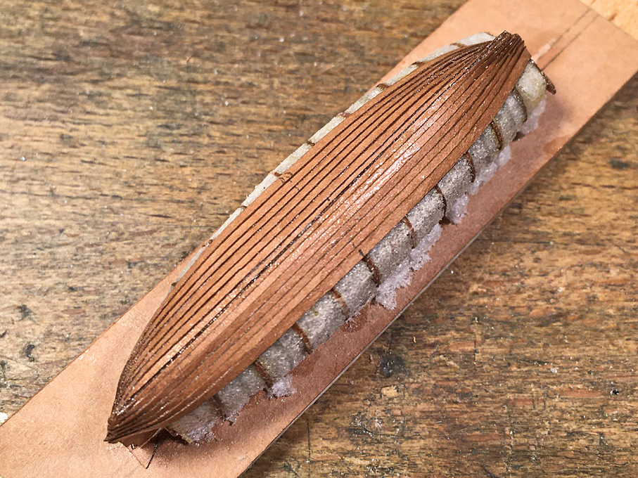
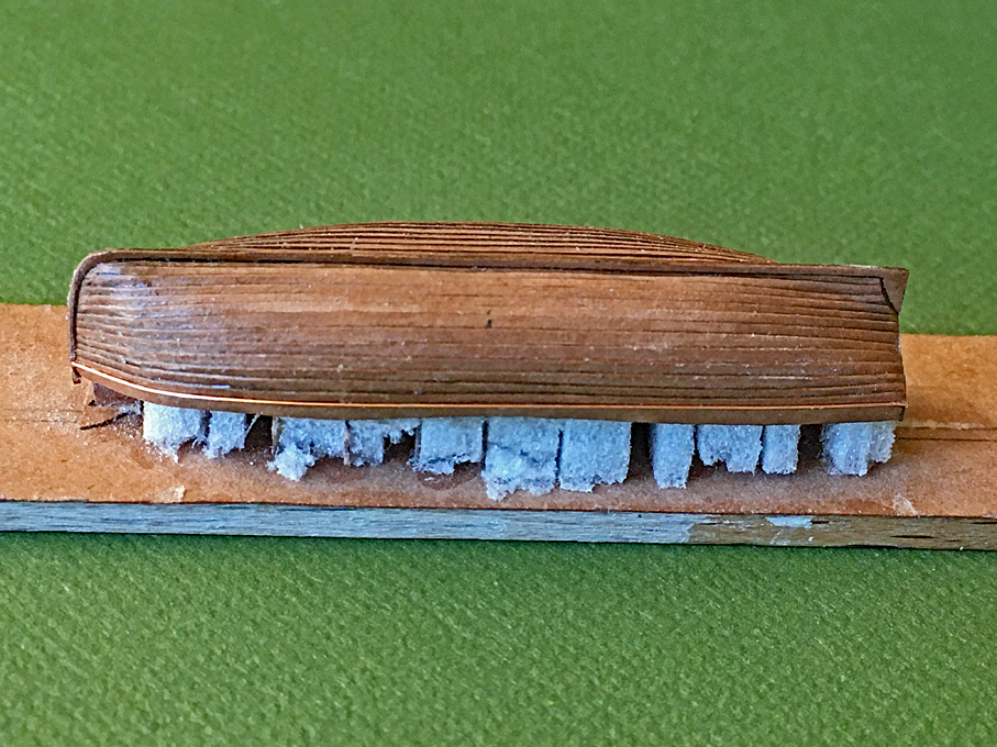
 Gig with simulated cover
I was debating with myself, whether I should first paint the hull and then add the cover, or the other way around. I opted for the second, as messing around with varnish, could damage the paintwork, even though it made it more difficult to hold the boat during (spray-)painting.
Basis for the cover was a piece of ironed-flat toilet-paper that was draped over the hull and then soaked in varnish resp. sanding filler. It was smoothed down over the edges and down to the rubbing strake. Once dry the paper was cut back to the rubbing-strake with a new scalpel-blade.
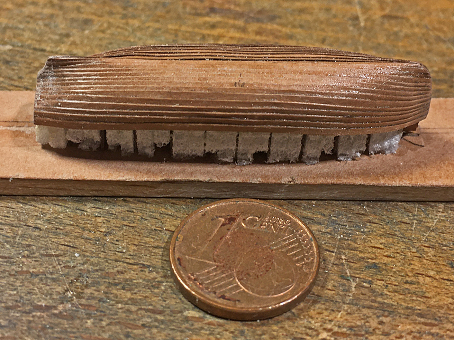
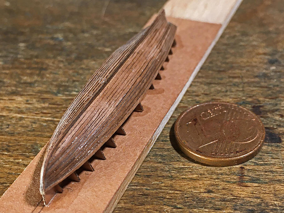
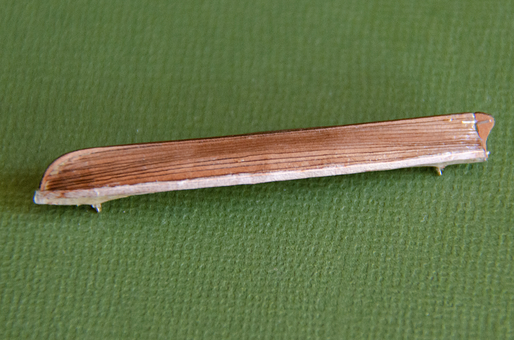
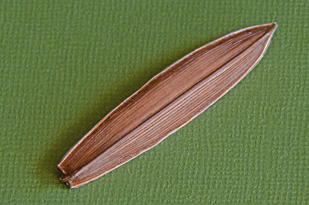 Underside of the gig showing planking
I almost forgot the rudder, that seems to have been kept shipped, when the boats were suspended in the davits. It was drawn on the basis of BRIX (1883) and laser-cut to be laminated from two layers. The pintels turned out to be far too small to reproduced, but the respective bands were simulated by flattened, tinned copper-wire.
 Gig with rudder shipped
The gig is now ready to be painted.
To be continued ....