The Ship Model Forum

The Ship Modelers Source
It is currently Thu Apr 18, 2024 7:23 am

All times are UTC - 6 hours [ DST ]


Post new topic Reply to topic  [ 384 posts ]  Go to page Previous  1 ... 5, 6, 7, 8, 9, 10, 11 ... 20  Next
Author Message
PostPosted: Sat Mar 13, 2021 12:26 pm 
Offline
User avatar

Joined: Mon Jan 10, 2005 5:30 pm
Posts: 5386
Location: Nr Southampton England
>>>> ...... The four anchor-cranes in place (they are about 10 mm high) ..... <<<<

:big_grin: :big_grin: :heh: :rolf_3: ... that big eh...?!! ... :lol_1: :lol_pound:

the quality of your engineering is REALLY very breathtaking!

BUT... ...

...exactly how long have you been building this model...?
I recall you had a hiatus when you( very beautifully!! ) re-engineered the resin kit of the Dutch Botter

viewtopic.php?f=59&t=152611&hilit=dutch

a short 7 years ago... :heh: :cool_2:

intrigued-- have you set a vague completion schedule...?

BEST WISHES mfg :wave_1:

Jim B

_________________
....I buy them at three times the speed I build 'em.... will I live long enough to empty my stash...?
http://www.modelshipgallery.com/gallery ... index.html

IPMS UK SIG (special interest group) www.finewaterline.com


Report this post
Top
 Profile  
Reply with quote  
PostPosted: Sat Mar 13, 2021 1:29 pm 
Online
User avatar

Joined: Wed Sep 28, 2011 12:04 pm
Posts: 1818
Location: Paris
I barely dare to say: I started work in 2007 I think, after a long gestation period, as I was not sure how I could deal with some of the flimsy details.

At that time various models of the same type, but in 1:100 and 1:50 scale were under construction and shown on a now defunct German forum. They were referring to my own Web-site for information. I had started to collate information there already many years earlier.

The building was interrupted several times for personal reasons: a move from the Netherlands to Paris, my marriage, tool-making projects, the Botter-project, etc. I am now pushing ahead, because I have another project lingering in my mind ... still a long way to go with several challenges ahead.

_________________
Eberhard

Former chairman Arbeitskreis historischer Schiffbau e.V. (German Association for Shipbuilding History)

--------------------------------------------------------------------------------------------------------------------------------------------------------------------------------------------

Image Image Image Image


Report this post
Top
 Profile  
Reply with quote  
PostPosted: Wed Mar 24, 2021 2:43 pm 
Offline
User avatar

Joined: Fri Dec 12, 2008 12:44 pm
Posts: 1775
Location: Herk-de-Stad, Belgium
Hello Wefalck,

I just found time to look into this build for the first time: it's awesome! :worship_1: Thank you ver much for this inspiring project! I will look it over very closely!

Maarten

_________________
"I've heard there's a wicked war a-blazing, and the taste of war I know so very well
Even now I see the foreign flag a-raising, their guns on fire as we sail into hell"
Roger Whittaker +9/13/2023


Report this post
Top
 Profile  
Reply with quote  
PostPosted: Thu Mar 25, 2021 12:00 am 
Offline
User avatar

Joined: Sun Mar 07, 2010 12:01 am
Posts: 1645
Location: Corvallis, Oregon, USA
You have dealt with the "flimsy details" very nicely!

Phil

_________________
A collision at sea will ruin your entire day. Aristotle


Report this post
Top
 Profile  
Reply with quote  
PostPosted: Fri Apr 02, 2021 2:24 pm 
Online
User avatar

Joined: Wed Sep 28, 2011 12:04 pm
Posts: 1818
Location: Paris
Thank you very much for your kind words !

********************************************

Stairs and ladders 2

While struggling with something else I will be reporting on shortly, as a diversion at looked at the stairs and ladders again.
I had fashioned the stairs from bakelite paper some three years ago (time is flying), but somehow I was not 100% happy with the result. The bakelite paper has a smooth surface and edge can be filed smooth too, but the glueing with CA was not quite so neat as I had wished. In principle it can be cleaned up well with a sharp chisel and fine steel-wool, but the inside edges of the steps are difficult to get to. Below is the result from that time:

Image
Selection of bakelite and styrene stairs (not yet trimmed to length)

Having now the laser-cutter at my disposal, I decided to try my luck with it. The photo-etching templates I had drawn quite a while ago where modified for use on the laser-cutter. The idea was to build up the stringers from three layers of 0.15 mm thick Canson-paper. The innermost layer has slots for the steps. The steps themselves are build up from two layers of paper.

Image
Laser-cut pieces for stairs waiting to be assembled

First the stringers were laminated together using lacquer and the edges sanded smooth, dito the steps. One stringer was then leaned against a little steel block with exactly square side on a glass plate. In this ‘jig’ the topmost and the bottom step were glued to the stringer with lacquer. Next the second stringer was glued on, while held exactly vertical with another little steel block. It was also checked that the step were at a right angle to the stringers. This assembly was let dry thoroughly. Still between the two steel blocks as ‘jib’ the remaining steps were slotted in and fixed with a drop of lacquer.

Using the laser-cutting process ensured that the upper ends of the ladder had a uniformly rounded shape and the bottom was cut off at the correct angle to the deck.

Image
Collection of stairs and ladders (the stairs are 4 to 5 mm wide)

The stairs were held in place (I assume) by shoes made from bronze. I cut out these shoes with the laser-cutter and attached them to the bottom end of the stringers. Eventually, they will be painted in bronze colour and glued to the deck.
The colour of the Canson-paper soaked in lacquer comes close to that of teak, from which they were made presumably on the prototype. However, the actual colour depends on the number of layers of shellac I happend to apply and varied at places. So I will have to spray-paint them eventually to also get an uniform sheen on the surface.

Image
Assembly of ladders for the barbette

The barbette is provided with two ladders, that allow the crew to scramble in and out of it, while for more leisurely access there is a narrow stair leading down from the bridge area. The stringers of the ladders, presumably steel on the prototype, were also cut from Canson-paper with holes for the rungs marked by the laser, which were opened up with a cutting reamer to exactly the right size for the wire to be used as rungs.

Image
Trimming flush the rungs of the ladders using a pair of cutting-tweezers

After the trimming a second layer without perforations was laminated on.

The ladders eventually will be painted white as the inside of the barbette will be.

To be continued ....

_________________
Eberhard

Former chairman Arbeitskreis historischer Schiffbau e.V. (German Association for Shipbuilding History)

--------------------------------------------------------------------------------------------------------------------------------------------------------------------------------------------

Image Image Image Image


Report this post
Top
 Profile  
Reply with quote  
PostPosted: Fri Apr 09, 2021 3:55 pm 
Online
User avatar

Joined: Wed Sep 28, 2011 12:04 pm
Posts: 1818
Location: Paris
Block-Making 1

The 1/160 scale from certain perspectives is rather inconvenient actually: too big to fake things and too small to do them properly due to practical limitations of tool sizes and materials dimensions.
Blocks at this scale would probably come in the range between 0.8 mm and 2 mm length. The latter would be a hefty 32 cm (or 13”) in real size, at least for smaller ships.
When I started dabbling with photo-etching in around 2007, I had the idea to fashion blocks from surface etched parts folded up and soldered together. As the need for blocks only arose now, I had never tried out the idea. Since then I got the laser-cutter and thought I might give the same principle a try, laminating the blocks from laser-cut pieces of paper. I am aware that larger blocks, build up from laser-cut wood pieces, are commercially available now.
My preoccupation was to produce blocks of the correct outside shape and through which the rope passes prototype fashion, i.e. to avoid the brick-like thingies from which the ropes sticks out vertically and then goes down with a sharp kink, as seen all too often on models.

**************

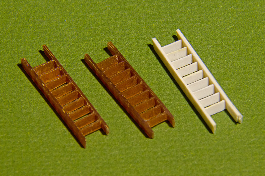
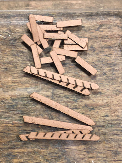
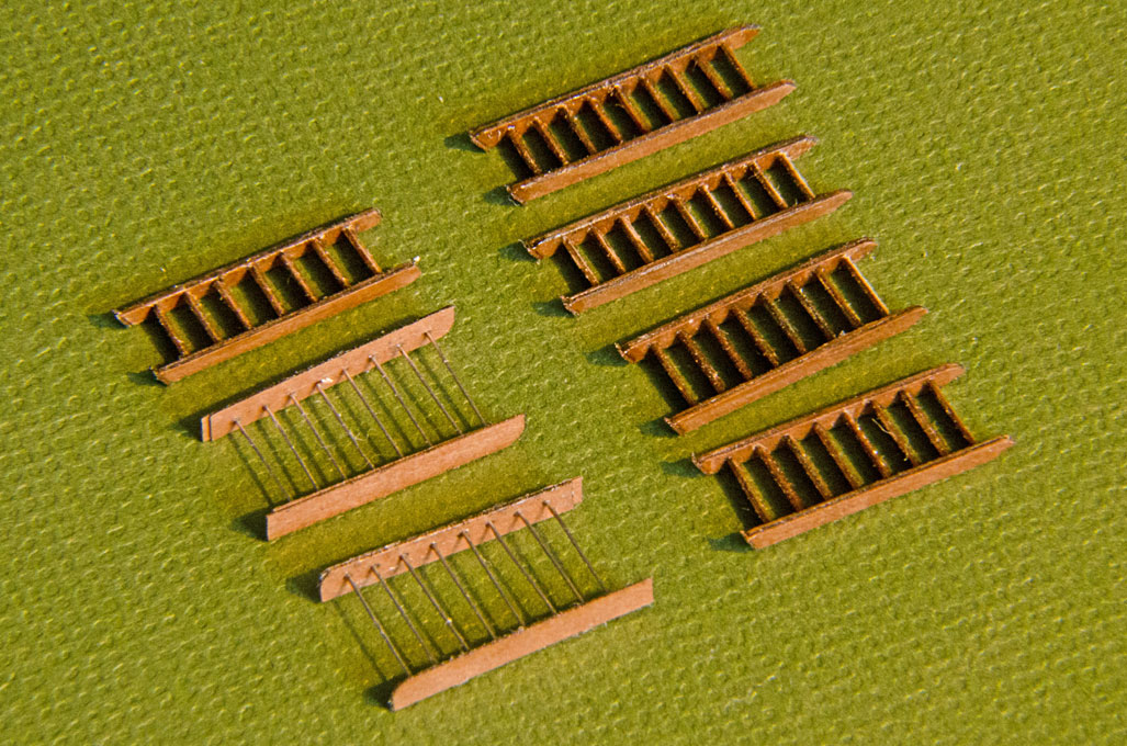
Warning, the following text describes some dead ends without success - As aligning the tiny parts correctly would be the main challenge, I drew the pieces at their correct relative location into small frets of several blocks that would be laminated onto each other. Once the lacquer was dry, the blocks could be separated. As I needed various double-blocks for the boat-davits and the anchor-cranes, I started out immediately with that challenge, thinking that, once mastered, single blocks would be comparatively easy to make. In fact, due to the thicknes of the Canson-paper, I needed seven layers, one for the outer shell on each side, one in the middle separating the sheaves, and the sheaves made up from two layers each. While the lamination as such worked well, aligning the seven frets precisely enough did not work too well. It also proved impossible to sand the tiny paper blocks to shape and smooth enough. The main problem, however, was that somehow the hole for passing through the rope always got clogged up. Opening it up with a drill then invariably let to the distruction of the block.
After a dozen of tries with different variants of the laser-cut parts to facilitate alignment etc. I finally gave up that idea.
Next came several experiments with the classical methods of carving blocks from billets, but using styrene or acrylic glass, rather than wood. While both materials are easy to drill, they proved too soft for shaping the grooves etc. cleanly, particularly the styrene. Attempts to cut slots for the sheaves, then to glue on a bottom piece to close the slots, and to later insert turned sheaves failed also. It was impossible to keep the 0.2 mm wide and 0.8 mm high slots clean enough from glue and cleaning them out afterwards at this dimension is hardly possible. Using brass and soldering equally failed to produce the desired result.

**************

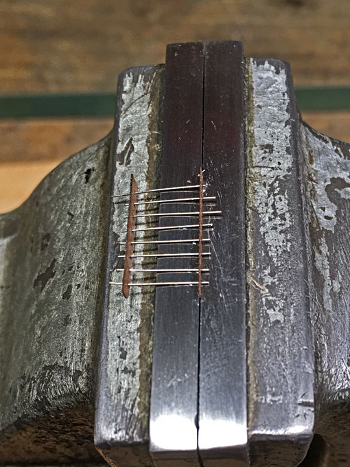
Now comes the success story - In the end I resorted to my trusted bakelite. This material is hard and does not smear, but is much more brittle than the other materials. Drilling 0.2 mm holes is still quite easy and doesn’t strain the drills too much.

Image
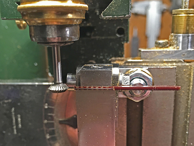
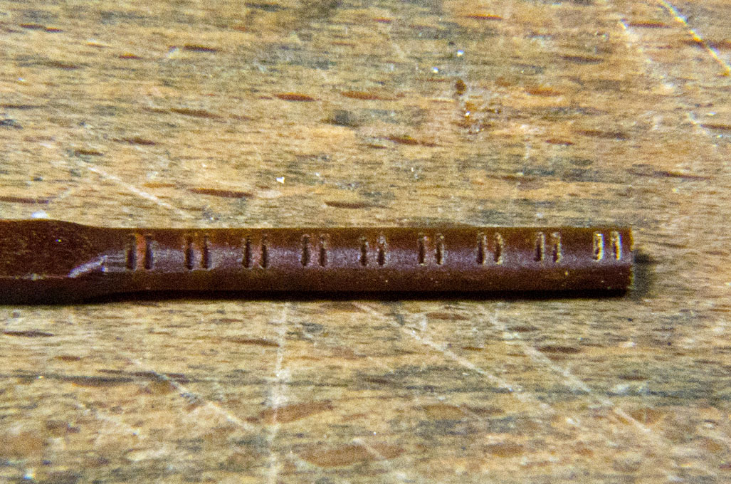
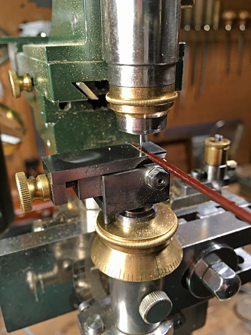
Drilling 0.2 mm holes into bakelite strips

I cut strips of the required width from a 1 mm sheet of bakelite to start with. The micro-mill then was used as a jig-borer and a row of holes drilled for a batch of blocks. Using a broken 0.2 mm drill, ground flat at the end, was then used as an end-mill to cut the grooves that simulate the slots for the sheaves.

Image
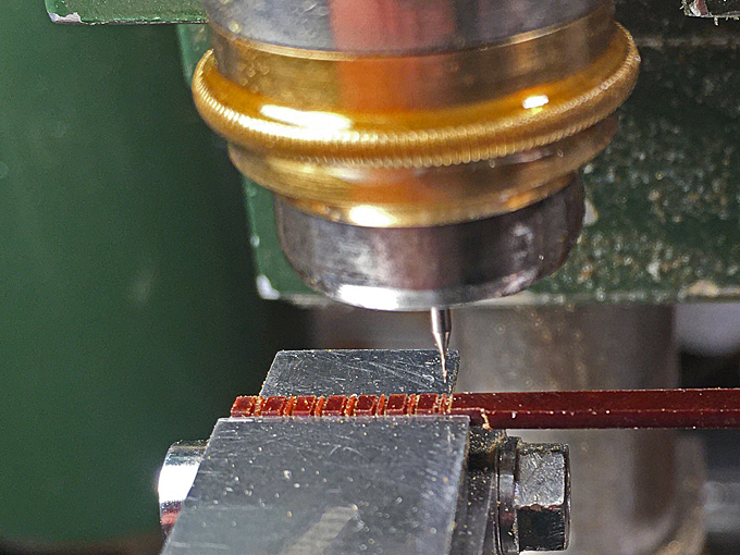
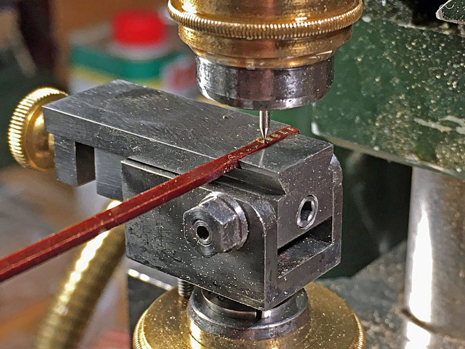
Milling 0.2 mm slots into bakelite strips

Image
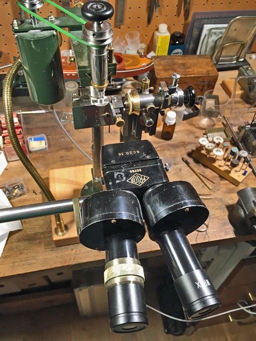
A stereo-microscope helps to safely perform the machinining with 0.2 mm tooling

The profile of the blocks was roughly milled to shape using various cone-shaped burrs. The final shaping was done by first hand-filing with a diamond nail-file and then using a fine abrasive wheel in the hand-held drill.

Image
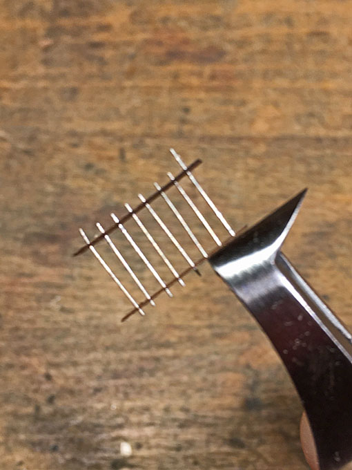
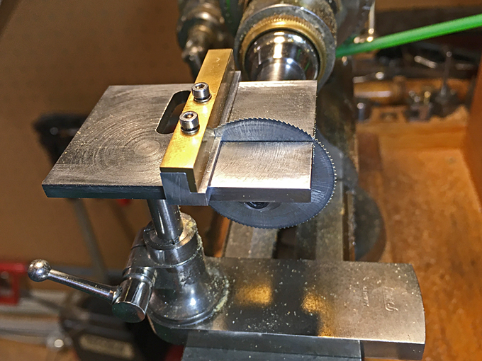
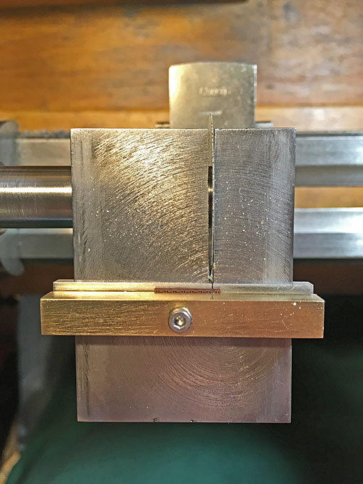
Row of double-blocks ready to be separated

To separate the blocks, the strip was taken into a collet of the dividing head and the blocks were sliced off with a circular saw. To prevent them from disappearing into any black holes of the workshop, the strip was backed with some adhesive tape.
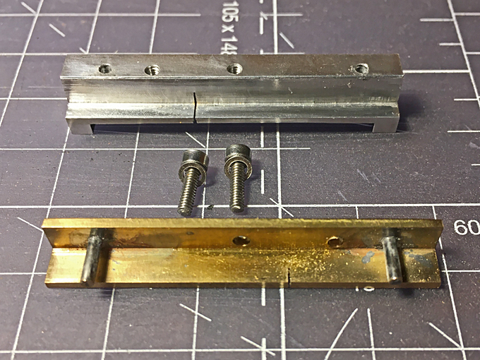
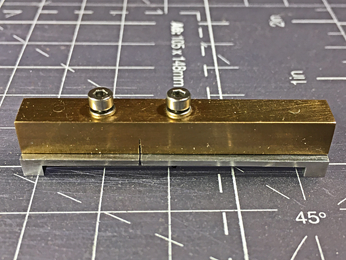
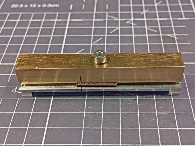
The sides of the block-shells were smoothed and shaped with the blocks clamped in a kind of special hand-held vice. This vice has brass insert jaws that are curved and stepped so as to clamp the block securely while working on it with an abrasive wheel.

Image
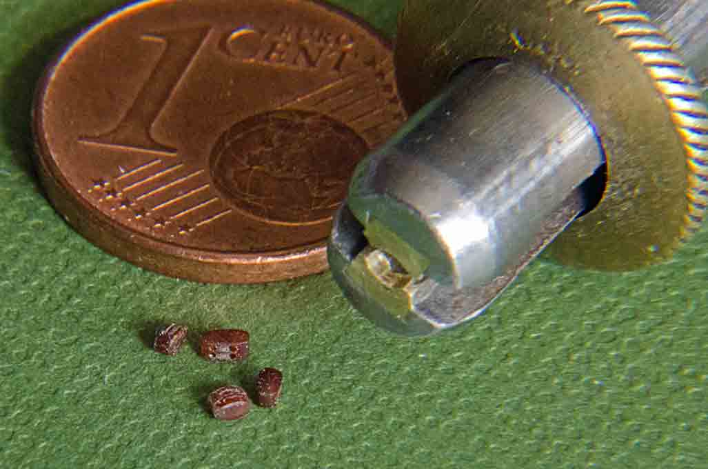
A collection of blocks and the special pin-vice to hold them

Image
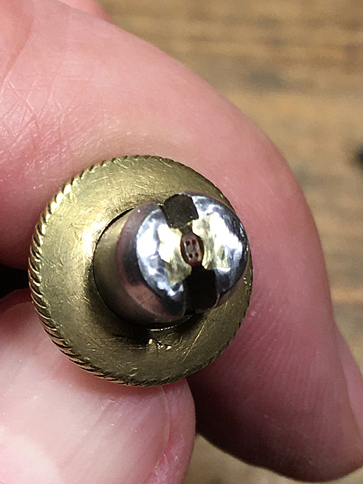
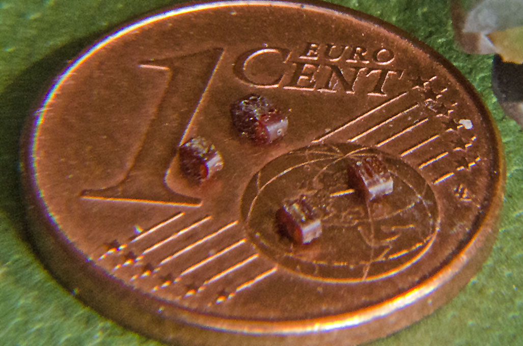
A collection of blocks and 1 Euro-Cent coin for comparison

Image
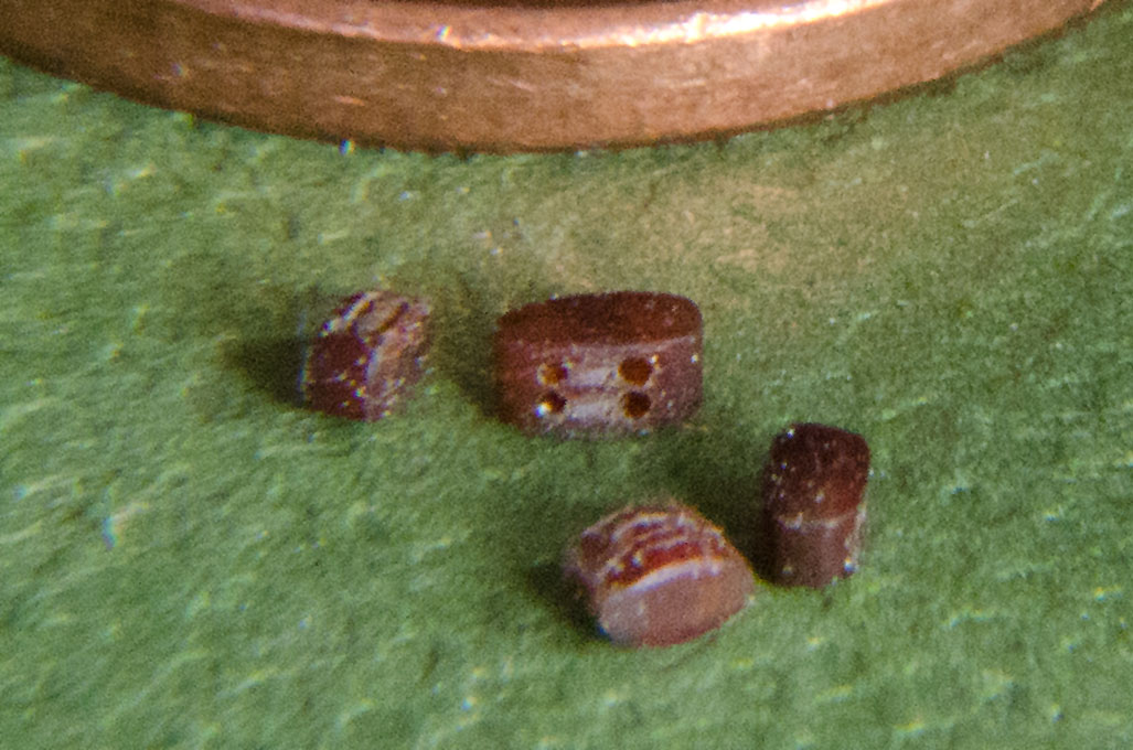
Two sizes of blocks of 2 mm and 1.6 mm length respectively

The blocks now have to be finished off with their external metal straps and hooks – another fiddly challenge ahead.

To be continued ....

_________________
Eberhard

Former chairman Arbeitskreis historischer Schiffbau e.V. (German Association for Shipbuilding History)

--------------------------------------------------------------------------------------------------------------------------------------------------------------------------------------------

Image Image Image Image


Report this post
Top
 Profile  
Reply with quote  
PostPosted: Fri Apr 09, 2021 5:14 pm 
Offline
User avatar

Joined: Mon Jan 10, 2005 5:30 pm
Posts: 5386
Location: Nr Southampton England
:thumbs_up_1: :thumbs_up_1: :thumbs_up_1:

I like the small stuff, ... but you take engineering to a new level!
Kudos for the perseverance!

JB :wave_1:

_________________
....I buy them at three times the speed I build 'em.... will I live long enough to empty my stash...?
http://www.modelshipgallery.com/gallery ... index.html

IPMS UK SIG (special interest group) www.finewaterline.com


Report this post
Top
 Profile  
Reply with quote  
PostPosted: Fri Apr 09, 2021 10:45 pm 
Offline
User avatar

Joined: Sun Mar 07, 2010 12:01 am
Posts: 1645
Location: Corvallis, Oregon, USA
wefalck,

One method I have seen to round of edges on tiny parts like blocks is to tumble them in a can, with a sandpaper "paddle" turned by an electric drill. The paddle consists of a flexible rectangular strip of sandpaper with a length equal to the inner diameter of the can and doubled over lengthwise so there is grit on both sides. It is attached at the center to a shaft that turns in a hole in the center of the lid for the can. When it turns the paddle bends, leaving space between the paddle and the interior of the can. The blocks bounce around inside the can, contacting the sandpaper. The result is the sharp edges are worn down smooth, and all sides are polished smooth.

You are familiar with Chuck Pissaro's (Syren Ship Models) posts on MSW.

Phil

_________________
A collision at sea will ruin your entire day. Aristotle


Report this post
Top
 Profile  
Reply with quote  
PostPosted: Sat Apr 10, 2021 4:10 am 
Online
User avatar

Joined: Wed Sep 28, 2011 12:04 pm
Posts: 1818
Location: Paris
I am, indeed, familiar with the tumbling method that has been borrowed from the lapidary and jewellery guys. I have tried a micro-version of it, using a plastic film can. The problem is that these tiny blocks are just too light and don't really 'tumble', unless you have a few dozens of them in the machine. The handful I need would just stick to the walls, without rolling about.

The technical problem is not really to round them off, that can be done easily with an rubberised abrasive wheel for the few I need and for the more modern flat type of block.

The challenge are the boreholes or slots and to round off the edges, so that the rope comes out of the block, as if it was going around a sheave. Down to sheave thickness of 0.3 mm it is not a problem - I have a very thin needle file and recently discovered diamond-studded wire down to 0.25 mm diameter that are used as fret-saws in lapidary (the Chines are fond of sawn-out pendants etc. in jade and other semi-precious stones, so there is a mass market for such wire saws). These wires can be used as flexible files. Below 0.25 mm begins the challenge - one has to remember that in 1/160 scale a 0.25 mm diameter rope would represent a hefty 40 mm one in real life ...

_________________
Eberhard

Former chairman Arbeitskreis historischer Schiffbau e.V. (German Association for Shipbuilding History)

--------------------------------------------------------------------------------------------------------------------------------------------------------------------------------------------

Image Image Image Image


Report this post
Top
 Profile  
Reply with quote  
PostPosted: Sun Jul 11, 2021 3:36 pm 
Online
User avatar

Joined: Wed Sep 28, 2011 12:04 pm
Posts: 1818
Location: Paris
Block-making 2

Somehow it seems to be always two steps ahead and then at least one step back … apart from the actual manufacturing problems, I somehow loose about 30% of the originally made blocks somewhere along the road. They jump of the tweezers and other tools … and the bakelite being light and elastic they jump far away and never seem to stay on the bench or in my apron …

I was not really entirely satisfied with the blocks I had turned out so far and tried out different variants of the above method over the past few weeks. Perhaps my improvised mill from a broken 0.2 mm drill was not sharp enough, anyway, the milled slots had a tendency to break out. I got myself from China (a lot cheaper than from European sources, where companies would have charged me for the shipping alone the amount of money that I paid for the item) a proper 0.2 mm end-mill, but the same happened. This is probably due to the fact that this kind of bakelite has a layered structure inherited from the paper that is used in its fabrication. Perhaps it would have been better to cut the block perpendicular to the layering.

Image
Cutting the grooves for the copper-wire straps

I tried out a method that has been shown on various fora, namely saw cuts along the full length of the block to simulate the grooves for the sheave and then to drill a hole for the rope. The rest of the procedure was as above.

Image
Drilling the blocks with a 0.2 mm drill

A problem was also cutting off the blocks from the billet. Somehow my method was tedious and at least about one in five blocks ended up flying around the workshop to be never found again. Not very efficient. So, I built a tiny gadget for the saw table of my lathe along the lines of the cross-cutting slides used on table-saws. This clamps the billet and the cut off block securely during the cutting and allows to locate the saw-cut precisely.

Image

Image

Image
A miniature cross-cutting slide for cutting off blocks from the billet

It is a piece of rectangular aluminium 8 mm x 6 mm into which a recess is milled at the bottom so that it fits over the saw table and is guided parallel to it. Then a step is milled into the front, over which a 6 mm x 6 mm brass angle fits to serve as down-hold. The angle is guided by two pins that have been hard-soldered into it. Two screws (I have added a second one since taking the pictures) push the angle down onto the workpiece. The saw slot was cut in situ with the 0.2 mm wide saw-blade that I am going to use with the gadget. Now I can cut off the blocks safely and quickly without the risk of losing them.

Image

Image
The cross-cutting slide used to on the watchmakers lathe saw-table

After separating, the blocks are shaped and rounded off individually using an abrasive wheel in the handheld drill. Earlier attempts with a small homemade tumbler were not successful, as the blocks are too small, too light, to few and the material too hard. Doing the rounding off in the hand-held vice works quite well.

All the previous methods were aimed to efficiently round off the entrance to the borehole in order to simulate the sheave and thus to make the rope enter and leave tangentially to the sheave. In order to achieve this now, the rounding-off has to be done manually. Not so easy as the bore is only 0.2 mm. For diameters above 0.25 mm I purchased a diamond-studded round fret-saw blade, but this is the smallest diameter on the market. After some head-scratching I fashioned a micro-chisel from a broken fretsaw-blade, which is held in a pin-vice for the time being (have to make a graver handle). With the chisel the groove is rounded into the bore, while the rough block is held in the hand-vice that I have adapted for the purpose.

The groove for the ‘iron’ straps were filed with a miniature (1 mm x 1 mm x 1mm) triangular file.

Image
Brass insert-jaws in the hand-vice, fashioned to hold blocks during manipulations

The next challenge was the external strapping with a hook at the end. In theory, the straps are strips of flat iron bar. While it was possible to flatten the copper wire that I was going to use in controlled way, the material broke easily and it was difficult to place the flat sections before twisting the ends together to form the hooks. Therefore, a practical concession needed to be made and the straps were going to be round. The next issue was to hold the block while attaching the strap. I made a special clamp from Novotex for the third-hand, but it did not hold the block securely enough. In the end it occurred to me that also the hand-held vice could be used, while clamping it into a larger vice. Still the overall operation is very delicate.

Finally, the tail end of the strap is cautiously bent into a hook. However, the copper wire is too soft to serve as a hook and also the structure of the two twisted ends is too obvious. Therefore, the hook was covered in a drop of soft-solder, which stiffens it and covers up to some extent the twisted structure. In addition, the back of the hook was somewhat flattened to better simulate the shape of a real hook.

Overall, this is turned out to be a very time-consuming procedure and I reckon, that it takes me upward of an hour per block, adding up all the different steps, notwithstanding that they are made in small batches. That’s ok for a small ship, but would be out of question for a larger sailing ship.

I am still not entirely happy with the fact that the blocks and in particular the hooks are not as uniform as I would have wished them to be.

Image
The lighter 2 mm blocks and the darker 1.6 mm long double blocks (they will be eventually all painted white)

To be continued ....

_________________
Eberhard

Former chairman Arbeitskreis historischer Schiffbau e.V. (German Association for Shipbuilding History)

--------------------------------------------------------------------------------------------------------------------------------------------------------------------------------------------

Image Image Image Image


Report this post
Top
 Profile  
Reply with quote  
PostPosted: Sun Jul 11, 2021 3:54 pm 
Offline
User avatar

Joined: Mon Jan 10, 2005 5:30 pm
Posts: 5386
Location: Nr Southampton England
>>>> .....I am still not entirely happy with the fact that the blocks and in particular the hooks are not as uniform as I would have wished them to be.....<<<

BUT.... they do look spectacular actually---and once rigged and installed you will be unable make direct comparisons-
-unlike now when they are lined up for close inspection and punishing self-critique.... :big_grin:

JIM B :wave_1:

_________________
....I buy them at three times the speed I build 'em.... will I live long enough to empty my stash...?
http://www.modelshipgallery.com/gallery ... index.html

IPMS UK SIG (special interest group) www.finewaterline.com


Report this post
Top
 Profile  
Reply with quote  
PostPosted: Fri Aug 13, 2021 1:10 am 
Offline
User avatar

Joined: Fri Dec 12, 2008 12:44 pm
Posts: 1775
Location: Herk-de-Stad, Belgium
Hi Wefalck,

I recognize the perfectionist! Of course the result will be dazzling, but sometimes at the cost of a gnawing dissatisfaction that it could have been better...

For myself I also had to learn this lesson of life: "better is the enemy of good".

It seems Voltaire quoted it this way: "Dans ses écrits, un sage Italien, dit que le mieux est l'ennemi du bien."

_________________
"I've heard there's a wicked war a-blazing, and the taste of war I know so very well
Even now I see the foreign flag a-raising, their guns on fire as we sail into hell"
Roger Whittaker +9/13/2023


Report this post
Top
 Profile  
Reply with quote  
PostPosted: Sat Aug 14, 2021 12:01 am 
Offline

Joined: Wed Jan 02, 2013 1:15 am
Posts: 5011
Wonderful to see the possibilities of various methods! Even if it's taking forever, perhaps the point, to explore the limits. We all have our personalities which drive the directions we go. I was a big airplane pilot for 30 years. Despite what most people might think, perfectionists make poor pilots, too much serious stuff going on that might be fatal to ignore. At least you get things done! Climbing a Himalayan Giant, each step does not have to be perfect, only a step (no missteps allowed).

We celebrate the pursuit of the possible!

Regards: Tom


Report this post
Top
 Profile  
Reply with quote  
PostPosted: Sat Aug 14, 2021 3:13 am 
Offline
User avatar

Joined: Fri Dec 12, 2008 12:44 pm
Posts: 1775
Location: Herk-de-Stad, Belgium
Fliger747 wrote:
Wonderful to see the possibilities of various methods! Even if it's taking forever, perhaps the point, to explore the limits. We all have our personalities which drive the directions we go. I was a big airplane pilot for 30 years. Despite what most people might think, perfectionists make poor pilots, too much serious stuff going on that might be fatal to ignore. At least you get things done! Climbing a Himalayan Giant, each step does not have to be perfect, only a step (no missteps allowed).

We celebrate the pursuit of the possible!

Regards: Tom

Hi Tom,

Different jobs require somewhat different personalities indeed. When you push forward the throttles in a 747 on the runway you're committed to fly the contraption safely until you're back on the chocks again. Within this period you have limited time and options to consider how to do it - so you better keep to the pre-defined and trained methods and procedures. But when building the big thing you have vast more time for considerations: the design of the same 747 wasn't completed within the endurance of the tanks, but took years of thinking and refining by a large team.

Model building (for a hobby) usually isn't very time constrained, but my remark was more about frustration: some people (I have the tendency too) to ponder the options to the extent you have no progress at all, and what you achieve rarely matches your imagined results. That tendency could kill the joy of the hobby altogether... So I sometimes must push myself and say: 'this is good enough - let's go to the next step'.

But I'm not sure we're taking up too much attention away from Wefalcks beautiful build of 'WESPE''... so let's return to him for further news about that. :smallsmile:

_________________
"I've heard there's a wicked war a-blazing, and the taste of war I know so very well
Even now I see the foreign flag a-raising, their guns on fire as we sail into hell"
Roger Whittaker +9/13/2023


Report this post
Top
 Profile  
Reply with quote  
PostPosted: Sat Aug 14, 2021 8:00 am 
Offline
User avatar

Joined: Tue Sep 29, 2020 4:35 pm
Posts: 1720
Location: Bretagne, France
It's a question of adjusting the cursor in the brain.

We all know this, more or less.

Exciting work to follow nonetheless. :thumbs_up_1:

_________________
Pascal

•Battleship Bretagne 3D: https://vu.fr/FvCY
•SS Delphine 3D: https://vu.fr/NeuO
•SS Nomadic 3D: https://vu.fr/tAyL
•USS Nokomis 3D: https://vu.fr/kntC
•USS Pamanset 3D: https://vu.fr/jXGQ


Report this post
Top
 Profile  
Reply with quote  
PostPosted: Sat Aug 14, 2021 10:37 am 
Online
User avatar

Joined: Wed Sep 28, 2011 12:04 pm
Posts: 1818
Location: Paris
Well, I have two ambitions - within the limitations of tools and materials: to make things to look like the prototype and to do the same things, as other people might do, say in 1:100 or even 1:50 scale.

Spending my (working) day in front of a screen, I quite like to do things with my hands and hand-operated machine tools. I have seen the possibilities of techniques, such as 3D-printing or laser-cutting for many years, but I am afraid that more and more of the free time is spent in front of a screen. One day, once I am a pensioner, I might go for UV-curing resin 3D-printing, just to keep up with the standards ...

_________________
Eberhard

Former chairman Arbeitskreis historischer Schiffbau e.V. (German Association for Shipbuilding History)

--------------------------------------------------------------------------------------------------------------------------------------------------------------------------------------------

Image Image Image Image


Report this post
Top
 Profile  
Reply with quote  
PostPosted: Sat Oct 16, 2021 4:14 pm 
Online
User avatar

Joined: Wed Sep 28, 2011 12:04 pm
Posts: 1818
Location: Paris
Some post-summer progress

It is quite amazing, how time passes – more than three months since the last up-date ! OK, I have been in sort of semi-vacation for six weeks in Spain, but then money-earning work seriously got into my way.

Normally, I leave painting as much as possible to the very end, just before the assembly stage. This avoids damage to the paintwork by handling the model or the problem of removing dust from it. However, I felt that the project had progressed to a point, where I wanted to see how everything comes together. This also boosts the motivation, rather getting lost in fabricating endlessly little pieces.

So, the model was given a good cleaning to remove dust, grease etc. The sequence of colours had to be carefully considered in order to work from the light ones to the dark ones. I also wanted to work inside out, because in this way masking was facilitated.

Image
Photograph of 1876 showing quite clearly the livery of SMS WESPE at the time.

The whole paint-work is done with acrylics from Vallejo (marketed here in France under the brand ‘Prince August’) and Schmincke (a German manufacturer).

Hence, I started with the white of the inside of the casemate, the bulwark and the walls of the deckhouse, which was spray-painted with the airbrush. Unfortunately, I had some trouble with the airbrush that had not been used for a while. Apparently, some paint had accumulated in the nozzle from insufficient cleaning over time. This particularly affected the white, which seems to have comparatively bigger pigment particles and is more difficult to spray anyway. Due to the various bits and pieces added to the bulwark etc., it is virtually impossible to rub down the paint and begin afresh … so the white paintwork is not as good as I had hoped for …

Image

The decks were not originally laid in wood (with the exception of the quarter deck and the floor of the casemate) or covered in linoleum at that time. They appear to have been painted with a mixture of tar and black oil-paint, with sand mixed into to provide a non-slip surface. I assumed that this mixture would attain a dark greyish colour with time due to weathering, similar to older tarmac. Prince August 996 (German ‘Panzergrau’ - tank-grey) seemed to be a suitable choice. All the deck areas were sprayed white together with the other parts to give a better key for hand-brushing. I began with painting the kicking-strips and water-ways between the bulwark stanchions and then progressed to several coats on the deck areas. All this painting was done by brush, as it would have been virtually impossible to mask-off the bulwark.

Image

The paint-schemes of the Prussian and then Imperial German Navy ships are reasonably well known for the years after 1867, as the ordinances were published in official gazettes that have survived. For the first couple of service years of SMS WESPE, the 1874 ordinance paint-scheme would have been applicable. This specifies that hulls below the waterline were to be red and above black, with a white boot-topping; another white strip was to be painted below the main rails; all ginger-bread work in white as well as all superstructures and deck-houses, ventilators, etc. Funnels and masts were to be painted yellow (buff). Photographic evidence indicates that there were some variations to this scheme for SMS WESPE, but I will discuss these, when I come to describe the painting of respective parts.

First, the narrow visible part of the underwater hull was painted in Vallejo 71.269 (red RAL 3000). This area was then masked off with Tamiya masking tape. The inside of the hull was also masked and the hull sprayed black.

Image

The bulwark-rail appears to have been varnished wood. It was first given a coat of Prince August 77 (bois-wood), followed by a light wash of 834 (bois transparent), which has a slightly lighter tone, followed by another light wash of Vallejo 71.074 (beige). Finally, a very light wash of Vallejo (transparent orange) was applied, which gives the wood a deep, warm tint.

The images above show the ‘raw’ paintwork. It still needs to be touched up and items such as the scrollwork needs to be refined. Eventually, there will be also a light weathering and ‘griming’ with pastels – the idea is to just show the effects of being in use, but with good maintenance.

To be continued ....

_________________
Eberhard

Former chairman Arbeitskreis historischer Schiffbau e.V. (German Association for Shipbuilding History)

--------------------------------------------------------------------------------------------------------------------------------------------------------------------------------------------

Image Image Image Image


Report this post
Top
 Profile  
Reply with quote  
PostPosted: Sun Oct 17, 2021 5:07 am 
Offline
User avatar

Joined: Fri Dec 12, 2008 12:44 pm
Posts: 1775
Location: Herk-de-Stad, Belgium
Looks very good to my eye, Wefalck! Photos are unforgiving, but I don't see any particular problems with the white parts, let alone the granularity of the pigment. Don't chastise yourself too much, we were at that before. But I share your self-critique, in the painting stage a beautifully built model sometimes becomes less perfect than you expected it to be.

_________________
"I've heard there's a wicked war a-blazing, and the taste of war I know so very well
Even now I see the foreign flag a-raising, their guns on fire as we sail into hell"
Roger Whittaker +9/13/2023


Report this post
Top
 Profile  
Reply with quote  
PostPosted: Sun Oct 17, 2021 6:03 am 
Online
User avatar

Joined: Wed Sep 28, 2011 12:04 pm
Posts: 1818
Location: Paris
Thanks Maarten, but photography can be also forgiving sometimes - in these shots taken from some distance and under diffuse daylight, you don't really see the issue. However, when viewed under artifical, glanzing light and close-up it looks rather different :woo_hoo:

_________________
Eberhard

Former chairman Arbeitskreis historischer Schiffbau e.V. (German Association for Shipbuilding History)

--------------------------------------------------------------------------------------------------------------------------------------------------------------------------------------------

Image Image Image Image


Report this post
Top
 Profile  
Reply with quote  
PostPosted: Sun Oct 17, 2021 1:17 pm 
Offline

Joined: Wed Jan 02, 2013 1:15 am
Posts: 5011
Again quite amazing work. The use of the laser cutter is of interest as is the use of various papers, sometimes impregnated. I built inclined ladders from Strathmore paper hand cut and assembled in a Jig. One reason the heavy paper worked well was that it goes together very well and strongly with carpenters wood glue. I have since replaced these with 3D printed ones, but yours are very satisfactory in the smallish 1:160scale. Laser cutting would have many uses, perhaps at some time I will adopt it. For larger item such as deck shapes, bulkheads etc I have been using a stencil cutting machine. It is quite good for such tasks, but for the smaller items your laser techniques are much superior. A very elaborate construction to successfully cut the blocks!

Thank you for sharing your techniques in detail, inspirational and though provoking.

Regards: Tom


Report this post
Top
 Profile  
Reply with quote  
Display posts from previous:  Sort by  
Post new topic Reply to topic  [ 384 posts ]  Go to page Previous  1 ... 5, 6, 7, 8, 9, 10, 11 ... 20  Next

All times are UTC - 6 hours [ DST ]


Who is online

Users browsing this forum: No registered users and 39 guests


You can post new topics in this forum
You can reply to topics in this forum
You cannot edit your posts in this forum
You cannot delete your posts in this forum
You cannot post attachments in this forum

Jump to:  
Powered by phpBB® Forum Software © phpBB Group