Thank you very much, gentlemen, for your kind words !
********************************************************
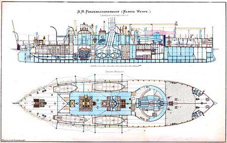
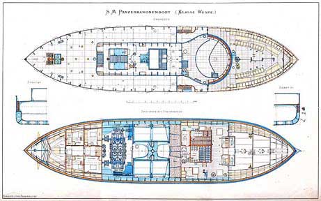
Ship’s BoatsWhile I was waiting for the wire for the chain-rails to arrive, I turned my attention to the ship’s boats. At that time there were four, two class IV cutters, a gig, and a joll-boat. In 1:160 they are all less than 50 mm long and 10 mm wide. Thanks to some research of various colleagues in Germany, we have reasonably good information on these boats, including lines and their constructional arrangement. In addition, there has been a text-book on boat construction, published since 1878 with updates every few years until 1929, which gives quite a few details on the naval boats.
I don’t quite feel like building four boats with all their internal constructional and fitting-out details, so I decided to show three of them covered, ready for the sea, while the small joll-boat will be shown ready for launching in an emergency, as it was custom. I don’t actually know, whether this boat or one of the cutters was used for the purpose, but assumed that the smaller boat would be easier to get into the water in a hurry, say in case of man-over-board.
An additional challenge is that these boats were clinker-built. I once built a clinker-dinghy in 1:60, which was only 50 mm long, but it was much wider and deeper and with wider strakes. These boats typically have ten strakes on each side.
I picked the long, but narrow and shallow gig first. I had a body plan available, drawn by a colleague some years ago. In addition, the text-book (BRIX, 1883) provides constructional details. The text indicates the dimension of the various parts.
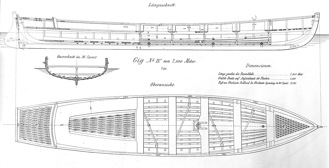 Drawing of gig from Brix (1883)
I decided on an overhead plank-on-bulkhead (POB) construction, which in a way seemed easier than trying to carve the hull with its hollow lines aft from a solid piece of wood using templates. The individual framing stations were taken from the body plan and drawn with additional material on the top in order to arrive at a common reference plane for overhead construction. The bulkhead were laid out for laser-cutting from Canson-paper.
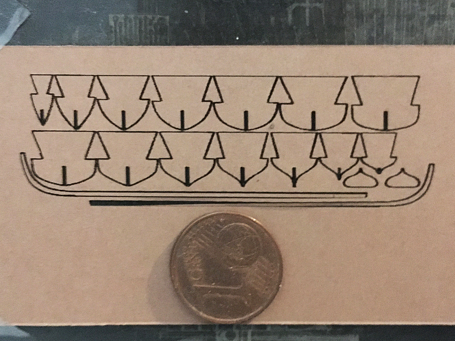
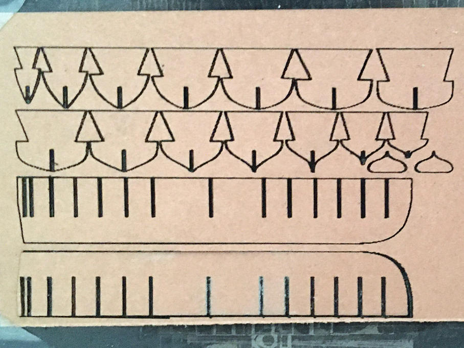 Laser-cut bulkheads and keel-pieces
A second drawing for laser-cutting contains another set of bulkhead and doubling pieces for the keel and stem, so that a rabbet for planking can be created. All pieces are doubled up after soaking in varnish to stiffen them.
 2nd set of laser-cut bulkheads and doubling pieces for the keel and stem
The pieces then were assembled as is tradition for POB-construction and mounted onto a piece of Canson-paper for extra stiffness. The whole assembly will then mounted in turn on a piece of wood to ease handling.
So far so good, but planking will be challenge, as the individual planks will be less than a millimetre wide overall. In theory, they should be only 0.06 mm thick in 1:160 scale, but I will give it a try with the 0.15 mm thick Canson-paper and see what it will look like. If the planking looks to coarse, I will have to start all-over again …
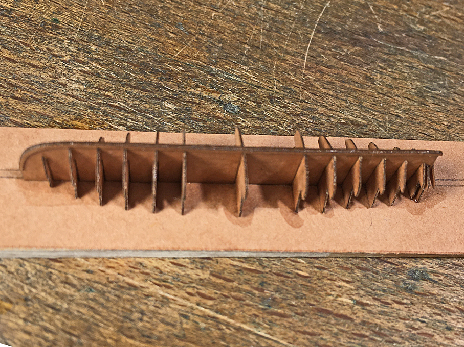 The assembled parts for the POB-construction
Tapering such planks by hand would be too much of a challenge an not quite feasible in paper I think. However, my 2D-CAD program gives the length of the Bezier-curves used to draw the outline of the frames. So, I simply took this length, divided it by 10, divided the result by 4 and then multiplied it by 5, which gives the plank width at each station line assuming that they overlap by about a quarter of their width (according to the drawing in BRIX, 1883). The contours of the planks were drawn for laser-cutting with this information. A first run, was not so successful – I will have to optimise the cutting parameters.
********
BRIX, A. (1883): Praktischer Schiffbau – Bootsbau.- 38 p. + 15 pl., Berlin (Hütte).
To be continued ....