The Ship Model Forum

The Ship Modelers Source
It is currently Sat Apr 20, 2024 8:15 am

All times are UTC - 6 hours [ DST ]


Post new topic Reply to topic  [ 540 posts ]  Go to page Previous  1 ... 20, 21, 22, 23, 24, 25, 26, 27  Next
Author Message
PostPosted: Tue Sep 30, 2014 7:17 am 
Offline

Joined: Fri Sep 25, 2009 6:28 am
Posts: 556
Location: Near Veenendaal, The Netherlands
Currently I'm in the process of thinking through how to continue on this build, with the hot topic being making the mold and hull.
I stumbled upon some issues for which I could well use your advice on how to continue best.
Due to the bulb I'm sure I need 2 halfs in order to be able to get the plug and later the final hull out of the mold.
At first I thought I would place a wooden plate just off the centreline, make the first mold, then move the plate to the other side of the centreline and make the other half of the mold.
When thinking this through down to the last detail I can think of I started wandering how I could fixate the plate in such a way that the plug isn´t damaged when removing it (using screws for fixation is no option here) but by which the plate is fixed so well that it can't be moved when making the mold.
Then I decided I'd place the wooden plate in between the 2 halfs of the mold, also when making the final hull but then I'd need to fill the bulb with resin so I can shape the bulb in the say 9mm where the plate will be as this can't be shaped the way the bow is shaped.
Then I thought I could place a plate in the transverse direction somewhere near the middle of the ship where the hull doesn't have any odd shapes like depth markings etc. (the plimsoll marking is usually placed at exactly half length and as that will also be made out of etched plate would not be a good place to make the joint between the 2 molds) but this way the mold might get stuck behind the etched parts when removing the mold.
I thought about making the mold a little flexible on purpose and stiffening the mold when the hull is being made by adding a frame work around it so the mold can be "folded" away from the markings but will be stiff enough when the hull is made.
Please let me know what you think of these methods and should I have missed a method, please feel free to inform me about it.

Greetings Josse

_________________
Making a complete new Well Enhancer, again scale 1:75.


Report this post
Top
 Profile  
Reply with quote  
PostPosted: Thu Oct 09, 2014 9:03 am 
Offline

Joined: Fri Sep 25, 2009 6:28 am
Posts: 556
Location: Near Veenendaal, The Netherlands
Update:
Image
The bow is slowly being made to the correct shape but there's still a lot to learn as I now have a gap in the bow.
Fortunately this is a plug so filling it up with filler is no big deal but this still isn't how one should want it to be...

Greetings Josse

_________________
Making a complete new Well Enhancer, again scale 1:75.


Report this post
Top
 Profile  
Reply with quote  
PostPosted: Fri Nov 14, 2014 5:58 am 
Offline

Joined: Fri Sep 25, 2009 6:28 am
Posts: 556
Location: Near Veenendaal, The Netherlands
Update:
Image
Took the old superstructure to show where I'm heading.
Image
Tweety paid a visit.
Image
The last bottom plate is being checked for correct fitting and was later adjusted in some places to fit.
Image
Glued the plate in place.

Greetings Josse

_________________
Making a complete new Well Enhancer, again scale 1:75.


Report this post
Top
 Profile  
Reply with quote  
PostPosted: Mon Nov 17, 2014 6:43 am 
Offline

Joined: Fri Sep 25, 2009 6:28 am
Posts: 556
Location: Near Veenendaal, The Netherlands
Hey guys,

I just had thought about the ballast tanks.
I had planned to use 1 big pump and 8 valves to serve a total of 8 tanks. Relais would make sure that as soon as 1 valve would be opened that the pump would fire up right away and as soon as the last valve would be closed the pump would be shut down as well.
This already wasn't all too complicated but still involves quite some electronics and one would need to pay quite some attention while the tanks are being filled.
Then I thought about the dive tanks used in model submarines which increase the size of the tank by moving a bulkhead thus sucking the water into the tank.
The main advantage is that the tank is always completely filled so there's no need for bulkheads to prevent the ship from rocking and rolling due to the water in the tanks.
This is a huge advantage for a ship this size and with heavy equipment at the top.
Another advantage is that I can now reduce the amount of tanks to 4 (compared to 8 in the original idea) or even 2, but then I can't use the tanks as counterweights to reduce the rocking and rolling of the ship.
I will use 2 motors or 2 servo's to control the tanks, 1 for the forward tanks and 1 for the aft tanks so that the SB and PS tanks fill to the same level.

I've also given some thought to how to give the command to fill the tanks, I originally planned to put a switchboard inside the hull but this means that a superstructure would have to be removed.
Then I thought about adding 2 3-way switches to the instrument panel, 1 per ballast tank, giving either the command to increase the size of the tank or decreasing the size of the tank.
This means that I can have all the weight in place whilst filling the tanks so that I can stop sucking water into the tanks when the ship has reached the waterline, much more accurately from the very first time onwards then when I need to put the superstructure back in place after filling the tanks.

What do you guys think about this idea?

Greetings Josse
This makes things much easier and I think will leave much more room for electronics, batteries and wiring.

_________________
Making a complete new Well Enhancer, again scale 1:75.


Report this post
Top
 Profile  
Reply with quote  
PostPosted: Mon Nov 17, 2014 4:13 pm 
Offline

Joined: Fri Sep 25, 2009 6:28 am
Posts: 556
Location: Near Veenendaal, The Netherlands
Update:
Image
The bulbous bow is starting to get it's shape step by step now but it still needs quite a lot of work before it looks like real ship.
Image
Trimmed the rear plate to place planks which can be shaped along the lines of the hull perfectly which the plate can't.
If the weather is good tomorrow I'll add polyester filler to this section of the hull, but as I'll be working under a "roof" there's a better chance of being able to add the filler.
Image
Looks like the stern indeed is straight!!!!
Image
Here I drew the lines for the final pieces of the bulbous bow which I can't saw now because people are sleeping here.

Greetings Josse

_________________
Making a complete new Well Enhancer, again scale 1:75.


Report this post
Top
 Profile  
Reply with quote  
PostPosted: Tue Nov 18, 2014 3:08 am 
Offline
User avatar

Joined: Sun Mar 13, 2005 11:51 am
Posts: 2407
Location: Belgium
Funny, I had exactly the same problem yesterday night with one of my projects... Ready to drill and saw, but somebody sleeping next to my workshop.

Anyway for the ballast tanks, I assume you will be using bladders inside those tanks? Otherwise those bulkheads will not be gas tight and you'll probably only fill by gravity = tank filling up till draft of the ship... Perhaps it would be better to have 4 tanks, 2 midships, port-and starboard and one forward and one aft? In that case you can put her upright and trim her as you wish. With only two tanks you could put her upright, but you can't trim her. 4 also gives you some spare in case of a problem.
If you do use the bladders, you'll have to think of a way to keep the tanks accessible in case a bladder would rupture. And of course the mechanism to make the bulkhead move. This will not be easy.

A regular pump system would be possible too though, although you have the risk of overflowing the tanks. You could work with 1 pump and use 3-way valves or similar to choose the tanks you want to fill in order to reduce the amount of valves and channels in use.
Lot of options there.

Good luck with the project though! Any progress on the 1-month (ahem?!) projects? Or is that female influence destroying your modelling aspirations? :heh:

_________________
The merchant shipyard


Report this post
Top
 Profile  
Reply with quote  
PostPosted: Tue Nov 18, 2014 3:17 am 
Offline

Joined: Fri Sep 25, 2009 6:28 am
Posts: 556
Location: Near Veenendaal, The Netherlands
Hi Neptune,

Thanks for the advice.

I didn't think it would be easy to build but that's fine to me, gives me a challenge.
I already had in mind to make the tanks accessible for maintaince.
What I had in minde was the following 4 tank configuration:
Image
This way I'd need only 2 motors to fill and empty the tanks.
My idea is also to put the batteries in between the 2 sets of tanks, possibly with a mechanism to shift the batteries around a bit to adjust trim in the transverse direction.
This would only need to be done when the ship is completed, after that it should remain the same.

The 1 month project came to a hold because I lost my job at the company that builds those ships, I think I need to get past that still...

Greetings Josse

_________________
Making a complete new Well Enhancer, again scale 1:75.


Report this post
Top
 Profile  
Reply with quote  
PostPosted: Tue Nov 18, 2014 7:04 am 
Offline
User avatar

Joined: Sun Mar 13, 2005 11:51 am
Posts: 2407
Location: Belgium
Depending how much weight you really need, you could also make the height of your tanks up till the waterline, that way you can fill them entirely by gravity (provide an airvent/overflow) by opening a sea valve. You'd only need a pump for emptying in that case, you could then connect both tanks on Portside and the ones on Starboard side to keep the ship upright during emptying. Generally emptying all of them together, but with a way to close one of the sides in case the ship starts listing.
For filling/trimming you could provide each tank with a seperate sea/water valve.
I don't like things that are permanently open to the water, it's like making a hole in your hull. If your tank leaks after maintenance or by damage, you can flood your hull without any way to stop it. Depending on which system you eventually choose, I'm sure you can optimise the system to limit the amount of equipment and channels needed.

_________________
The merchant shipyard


Report this post
Top
 Profile  
Reply with quote  
PostPosted: Tue Nov 18, 2014 7:53 am 
Offline

Joined: Fri Sep 25, 2009 6:28 am
Posts: 556
Location: Near Veenendaal, The Netherlands
Hi Neptune,

I understand your reasoning.
It certainly will present a challenge to make it permanently watertight.
Tests should prove watertightness after maintaince before sending her out in the open.
Also, I can add water detection methods under the tank to warn me when a tank is leaking so I'll have time to get her back and out of the water in time.
That can be as simple as a wire cut in 2 in the end of the tank as I have circular tanks in mind.

On another forum I heard that the tanks with moveable end (which can be bought in store ready for use at high costs, Engel manufactures these tanks) is an unbeatable ballast tank system, provided you make the tanks properly watertight.

I'll give this some more thoughts.

Greetings Josse

_________________
Making a complete new Well Enhancer, again scale 1:75.


Report this post
Top
 Profile  
Reply with quote  
PostPosted: Tue Nov 18, 2014 9:46 am 
Offline

Joined: Fri Sep 25, 2009 6:28 am
Posts: 556
Location: Near Veenendaal, The Netherlands
Update:
Image
From hardly any bulb to rough bulb in 1 day.
Image
Also shaped the front most part of the bulb, further back still needs lot of attention though.
I checked the shape by holding a photo of the real ship from the same angle next to my model and I'm proudly telling you now that the shape is very close to the original where I'm far enough with shaping.
The bulb here is much better then the previous which turned out to be much too narrow...
Image

Image

Image

Image
This shows that this certainly is quite a big boat...

Greetings Josse

_________________
Making a complete new Well Enhancer, again scale 1:75.


Report this post
Top
 Profile  
Reply with quote  
PostPosted: Wed Nov 19, 2014 3:03 am 
Offline

Joined: Fri Sep 25, 2009 6:28 am
Posts: 556
Location: Near Veenendaal, The Netherlands
Update:
Image
Put the old hull next to the new hull for comparison.
There's still a lot to learn, also on the new hull but the shape is what it should be.
The old hull has now been stripped of the last useful things and will be moved to the demolition yard where 2 small children will take her apart.
Image
In this photo the difference in width of the bulbous bow can be clearly seen.
I remember having doubts about the bulb on the old hull some 6 years ago, wandering if it shouldn't be wider, never checked but now it turns out that my feeling was correct.
Image
Today the sanding and filling will continue.

Greetings Josse

_________________
Making a complete new Well Enhancer, again scale 1:75.


Report this post
Top
 Profile  
Reply with quote  
PostPosted: Tue Nov 25, 2014 4:23 pm 
Offline

Joined: Fri Sep 25, 2009 6:28 am
Posts: 556
Location: Near Veenendaal, The Netherlands
Update:
Image
Sanded outside with good result.
That can't be said about the new sanding paper I bought the day before, it was torn apart in 10 minutes of sanding...
Image
The stern is also slowly taking shape though it's still far behind the bow.
Image
The bow after half an hour of wet sanding the bow now really starts to look like it should be, but I'm not quite there yet.

Greetings Josse

_________________
Making a complete new Well Enhancer, again scale 1:75.


Report this post
Top
 Profile  
Reply with quote  
PostPosted: Thu Jan 29, 2015 6:31 am 
Offline
User avatar

Joined: Wed Jul 21, 2010 2:44 am
Posts: 474
Location: Dumfries, Scotland
Josse

I know it sounds a bit drastic but unless you need the hull plug for something other than it's main purpose, after making a mould, you could always cut the whole finished plug straight down the middle (length ways). You can carefully mark the centre line and feed the upturned plug through the band saw (assuming it will fit). You would then need to add a small thickness to each cut surface, thin ply say 1mm, to make up for material loss. Each plug half can then be glued and screwed to a strong flat board which would be the base for creating your GRP mould. The lip around the edge of the mould would then be smooth and dead flat.
I usually design my plugs to be in two halves from the outset, although I have cut plugs lengthways as described above. I sounds scary but as long as the band saw blade is sharp and you take your time it does work.
My current submarine build on this forum was done this way.

Good luck.

PS I no longer bother with "sandpaper". Find a trade outlet who supply car re finishing supplies. The abrasive sheets used in the automotive industry are more expensive but last (with care) for ages and ages and save time. The fine foam backed abrasive pads are excellent for the final stages of smoothing the hull plug.

_________________
PICKETBOAT

www.chyldshallmodelshipyard.com


Report this post
Top
 Profile  
Reply with quote  
PostPosted: Sun Feb 01, 2015 3:21 pm 
Offline

Joined: Fri Sep 25, 2009 6:28 am
Posts: 556
Location: Near Veenendaal, The Netherlands
Hi Picketboat,

Thanks for the great advice!!!
I've looked into it and it seems to be a great way to go.

Greetings Josse

_________________
Making a complete new Well Enhancer, again scale 1:75.


Report this post
Top
 Profile  
Reply with quote  
PostPosted: Thu Feb 05, 2015 8:50 am 
Offline

Joined: Fri Sep 25, 2009 6:28 am
Posts: 556
Location: Near Veenendaal, The Netherlands
Finally an update again, though not really a big one...
Image
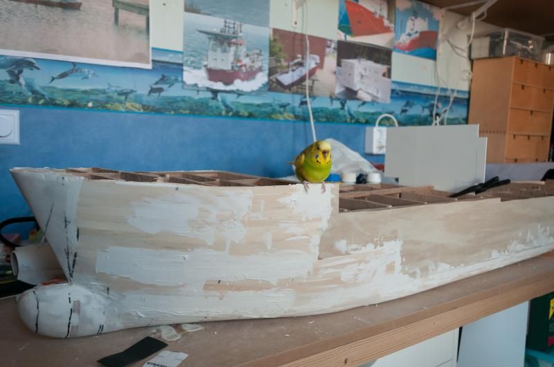
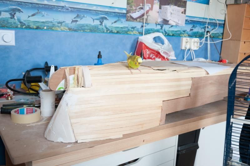
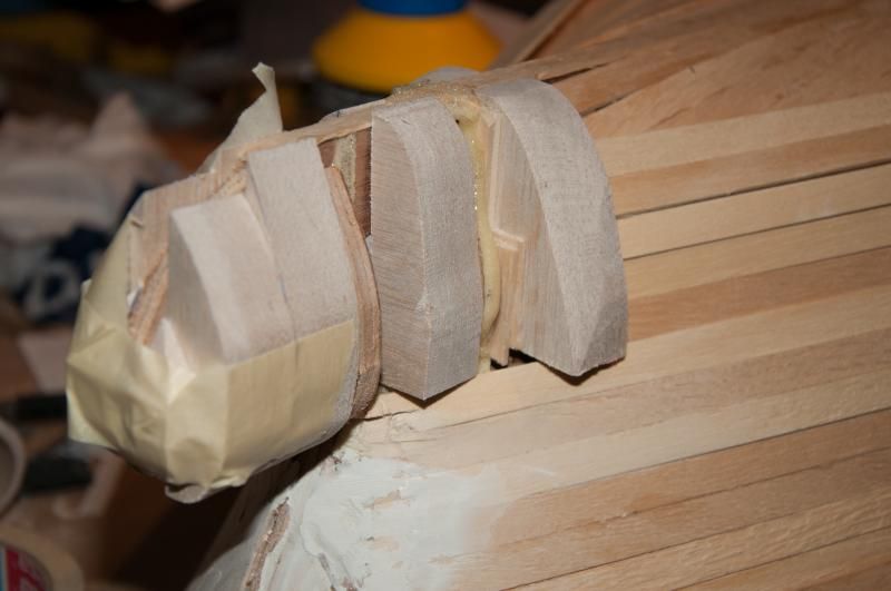
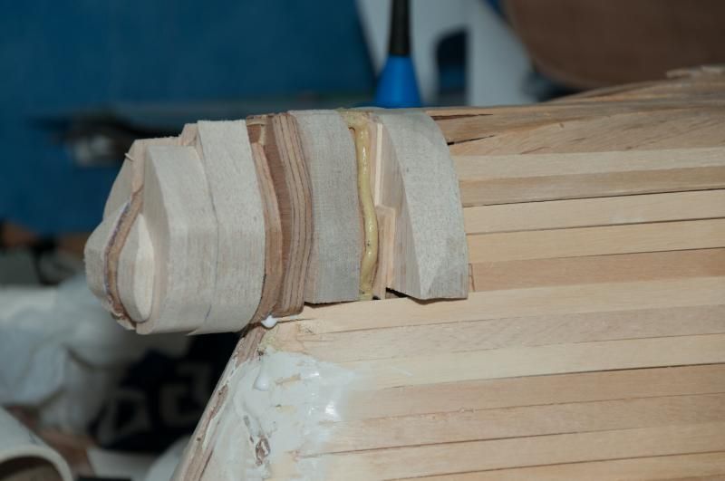
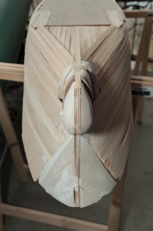
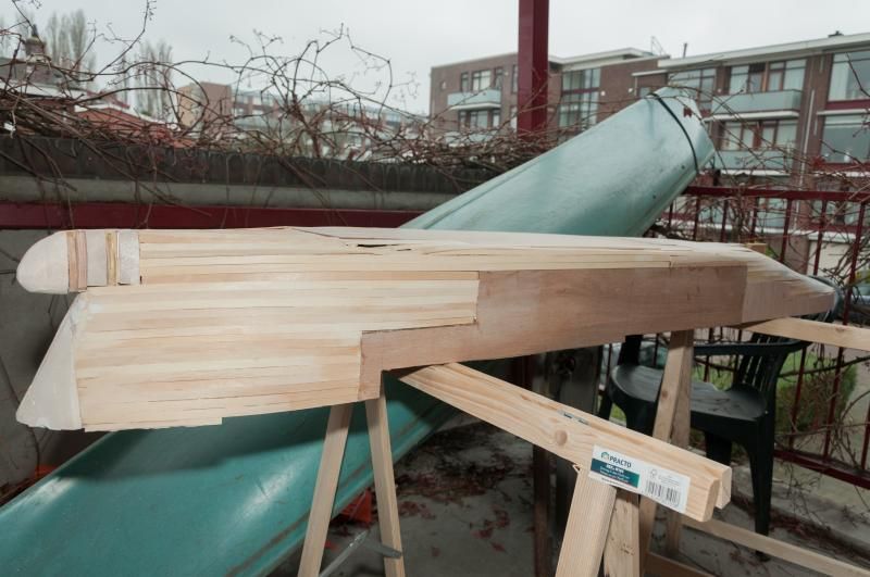
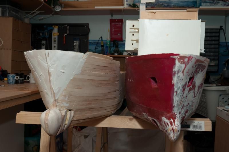
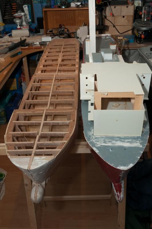
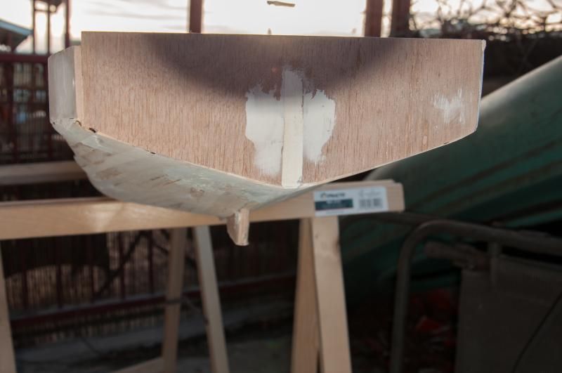
Tweety has been aboard again!!
Image
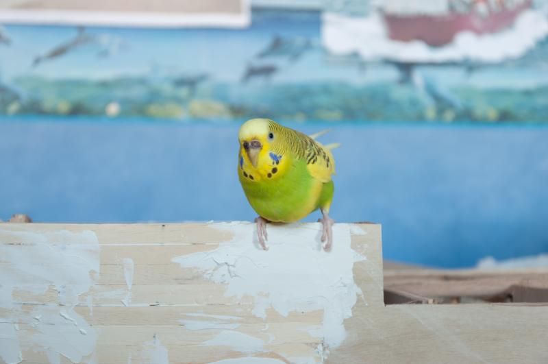
Up close and personal.
Image
Nothing much has changed other then ideas I had about how to proceed with this build.
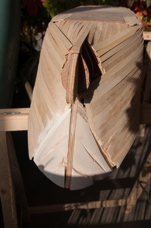
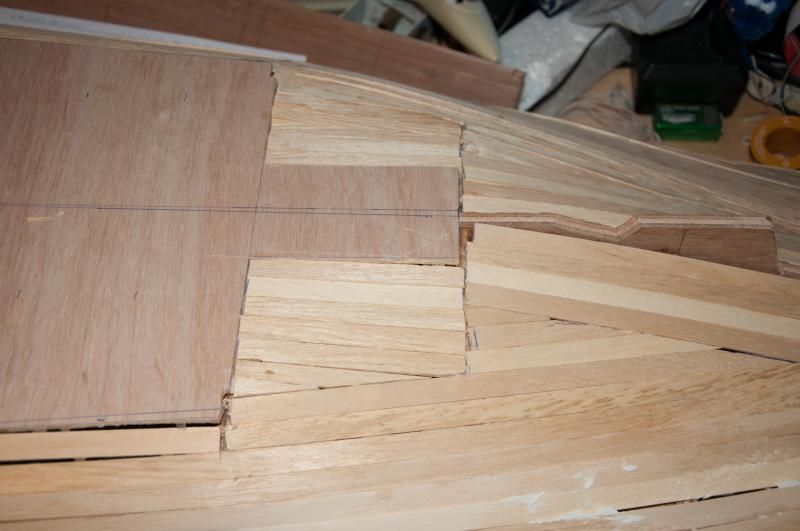
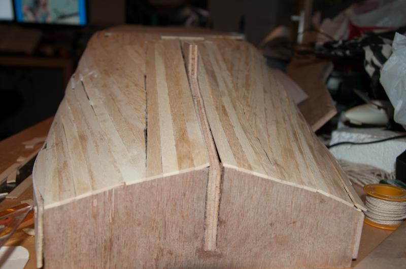
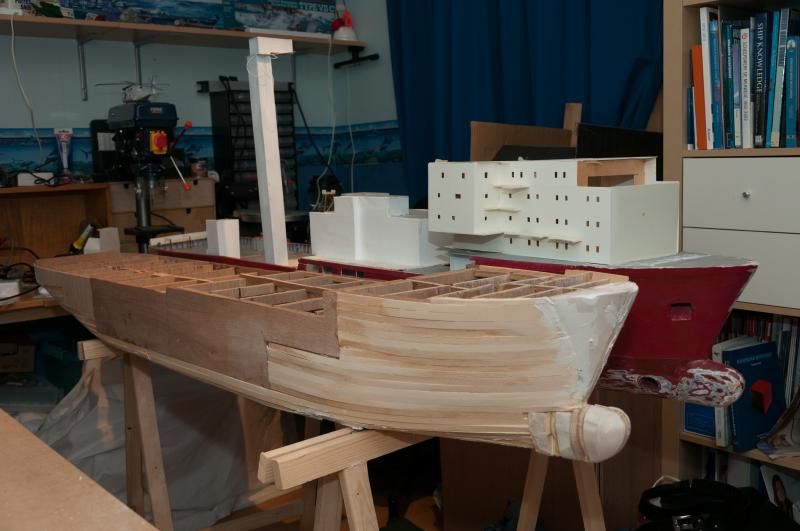
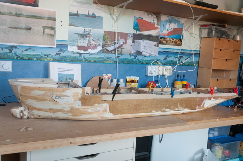
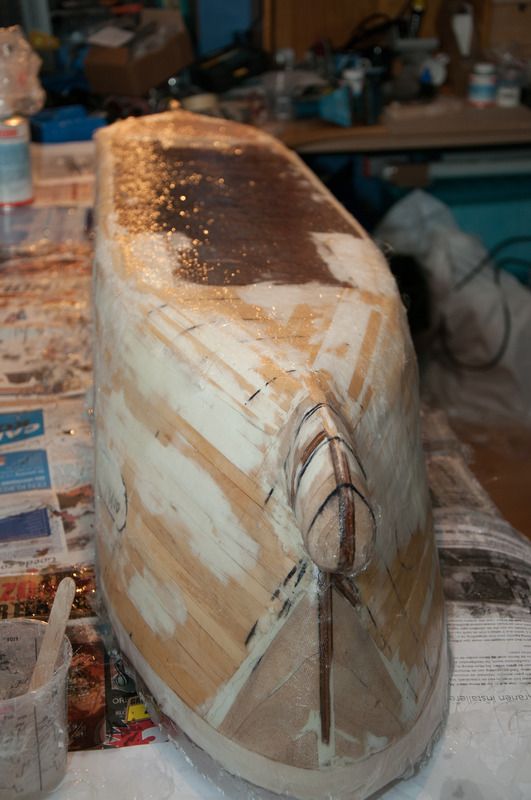
The wooden hull will actually be the hull rather then just a plug, this is because the major reasons for making a GRP hull have fallen apart: I checked the weight calculation and found a few items that had weights estimated kilo's heavier then they'll ever be...
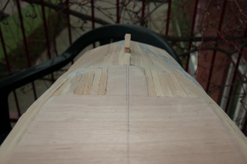
Beside that, as can be seen in this post, the wooden hull still offers plenty of space as it's designed now for all the functions and it saves me weight in ballast.
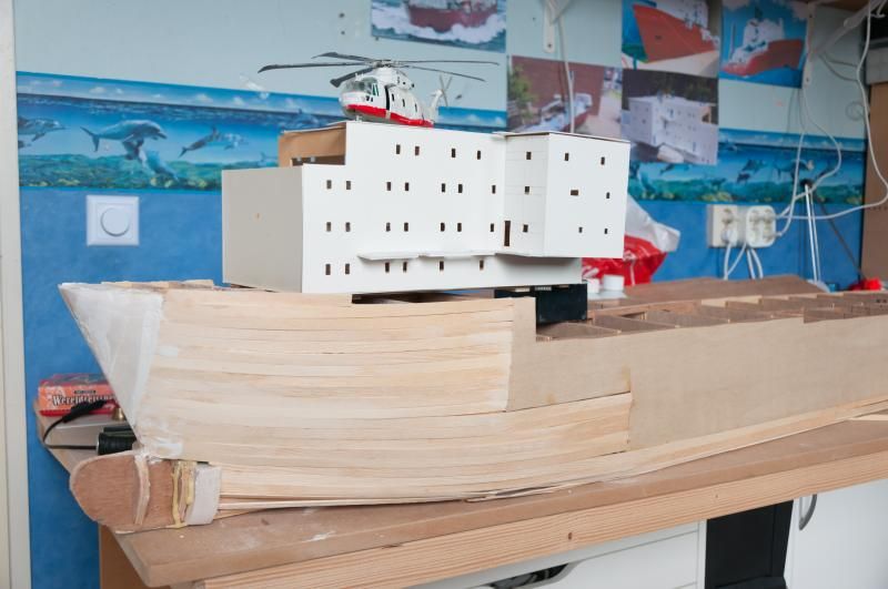
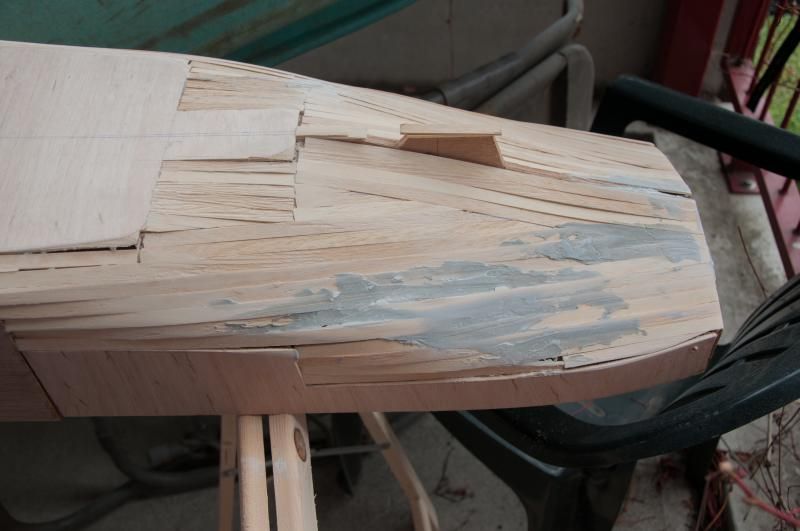
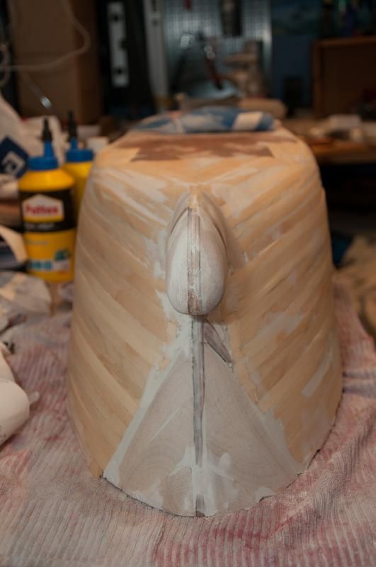
Then there is the ballast item: I had been thinking about using ballast tanks but recently I found out that there is no room for big enough ballast tanks in the stern due to the moonpool which has become more important then it ever was.
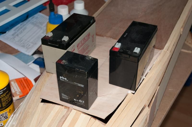
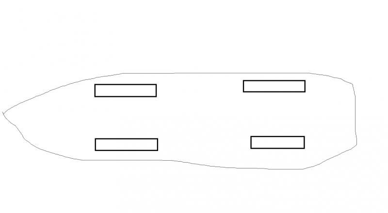
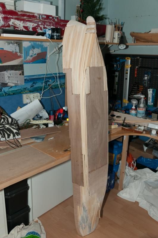
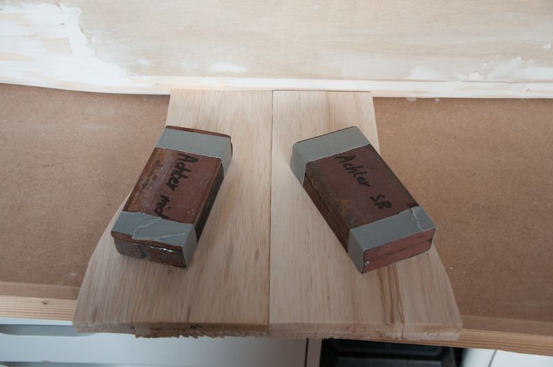
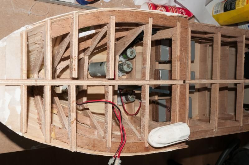
Therefore I decided that steel ballast isn't quite a bad thing to have so in this photo you can see almost 5 kilos of steel ballast packed together in 3 packs.
There will be a frame to keep it from moving about.
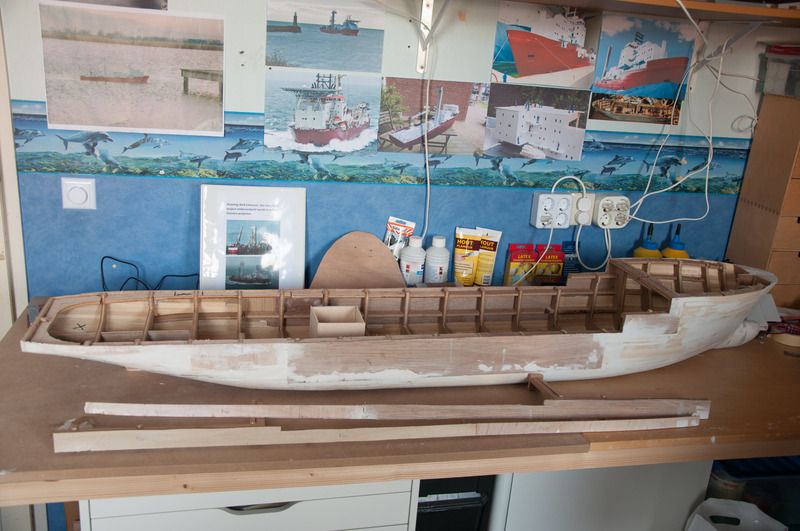
Then there are 3 pumps, 2 for cooling water and 1 to flush the anchors.
There are also 2 Speed 500-size engines to power the bowthrusters and there is an Arduino Mega without it's to be designed PCB.
Image
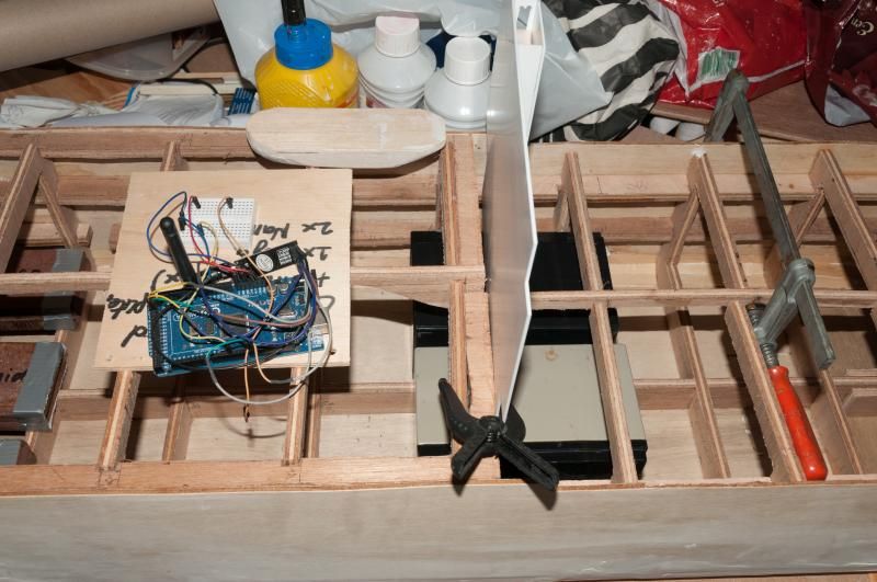
This is midships with 2 batteries which will be turned around so the tops will end up in the middle with the batteries placed as far away from each other as possible and the batteries will also be placed in a frame to keep it from moving about.
The central computer (without it's still to be designed PCB) is placed on deck here because there is no room to put it in between the frames at the top.
Image
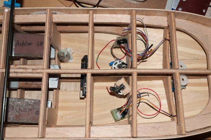
Here is the stern with 2 Speed 500 E engines and 2 stepper motors and 1 cooling water pump, there is also an Arduino Mega for which I will also design a PCB.
There is also a little over 5kilos of ballast packed together like in the bow.

Greetings Josse

_________________
Making a complete new Well Enhancer, again scale 1:75.


Report this post
Top
 Profile  
Reply with quote  
PostPosted: Fri Apr 17, 2015 3:32 am 
Offline

Joined: Fri Sep 25, 2009 6:28 am
Posts: 556
Location: Near Veenendaal, The Netherlands
Update:
Image
The mold for the bow was too hard to get in shape (it already cost me 3 pieces of sanding paper) so I decided to make a new mold out of balsa which is being glued in the photo.
Image
The molds have been cut off the hull as preparation for adding the epoxy, which will be due to happen one of these days if the weather is good enough.

Groetings Josse

_________________
Making a complete new Well Enhancer, again scale 1:75.


Report this post
Top
 Profile  
Reply with quote  
PostPosted: Mon Apr 20, 2015 9:12 am 
Offline
User avatar

Joined: Sun Mar 13, 2005 11:51 am
Posts: 2407
Location: Belgium
Looks like a nice and smooth result on that bow. Good luck with the epoxy, I'll be following that carefully as I'm also looking for Epoxy for a next project. So any experiences you want to share are welcome!
Read a lot about it, but still a little scared to get started with it. :heh:

_________________
The merchant shipyard


Report this post
Top
 Profile  
Reply with quote  
PostPosted: Wed Apr 22, 2015 11:37 am 
Offline

Joined: Fri Sep 25, 2009 6:28 am
Posts: 556
Location: Near Veenendaal, The Netherlands
Hi Neptune,

Thanks for the kind words.

Last Monday I applied the injection resin to the hull to make the wood watertight, with a helping hand off my girlfriend, and today I applied the same resin to the inside off the hull, 3 layers on the outside and 1 on the inside.
I think I might start working with the epoxy resin next week so I'll probably start preparing the fibreglass during this week so I'll have no worries about that next week.

Greetings Josse

_________________
Making a complete new Well Enhancer, again scale 1:75.


Report this post
Top
 Profile  
Reply with quote  
PostPosted: Thu May 07, 2015 6:00 am 
Offline

Joined: Fri Sep 25, 2009 6:28 am
Posts: 556
Location: Near Veenendaal, The Netherlands
Update:
Image
The boat is now almost ready to receive the first layer of epoxy and fibreglass, which will hopefully be tomorrow.

Greetings Josse

_________________
Making a complete new Well Enhancer, again scale 1:75.


Report this post
Top
 Profile  
Reply with quote  
PostPosted: Thu May 07, 2015 2:04 pm 
Offline

Joined: Fri Sep 25, 2009 6:28 am
Posts: 556
Location: Near Veenendaal, The Netherlands
Update:
Image
Prepared my desk for applying the epoxy.
Image
Put the glass in place as much as possible but I've learned now that it is much easier to first apply a coat of epoxy and then put the glass in place and then apply a second layer of epoxy.
Image
I used 2 of these cups to apply enough epoxy.
Image
Applied the epoxy to the hull with a much better result then the last time but there's still enough room for improvement.
I used rovimat for the middle section of the hull which has fibres in all directions but I really don't like working with it so I'll use the woven fibreglass only next time.

Greetings Josse

_________________
Making a complete new Well Enhancer, again scale 1:75.


Report this post
Top
 Profile  
Reply with quote  
Display posts from previous:  Sort by  
Post new topic Reply to topic  [ 540 posts ]  Go to page Previous  1 ... 20, 21, 22, 23, 24, 25, 26, 27  Next

All times are UTC - 6 hours [ DST ]


Who is online

Users browsing this forum: No registered users and 10 guests


You can post new topics in this forum
You can reply to topics in this forum
You cannot edit your posts in this forum
You cannot delete your posts in this forum
You cannot post attachments in this forum

Jump to:  
Powered by phpBB® Forum Software © phpBB Group