The Ship Model Forum

The Ship Modelers Source
It is currently Wed Apr 17, 2024 7:05 pm

All times are UTC - 6 hours [ DST ]


Post new topic Reply to topic  [ 97 posts ]  Go to page 1, 2, 3, 4, 5  Next
Author Message
PostPosted: Sat Apr 02, 2011 1:43 pm 
Offline

Joined: Wed Dec 12, 2007 8:24 pm
Posts: 80
Ok here goes, first off I've never made a boat this big before, scratch built some merchant vessels in 1/700 many years ago and did all the usual plastic model tricks and trips in various scales, but nothing this big or daunting....if anyone needs tips in how not to do it then this'll be the place to watch :).

The title is a little loose right now, I've always been interested in USN from WWII to the present day and seeing some of the models now coming along I figured it was time to get stuck in and see what sort off mess I can make of it all :).

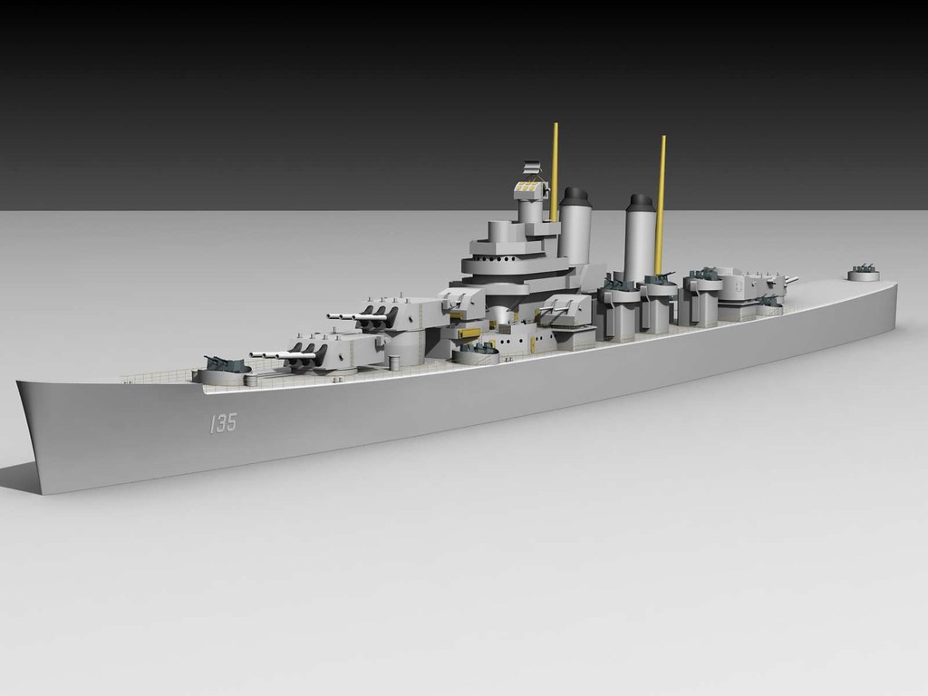
I'm stuck with 1:96 as that seems to be the best size for mid range models (that one can lift on ones own) and after market parts and extras and just big enough to have presence (I've been modeling virtual models for 13 years so a seven foot warship fits that quite well I think). The choice has come down to two classes, Baltimore's or Cleveland's, both of which have pluses and minuses, I like the Cleveland's post war, especially the mixed weapon vessels from the 60's, though a WWII one would be nice too. The Baltimore's I like in WWII (they seem a little more chunky/stocky) as well as Korea and also like the mixed weapons and 'tall ladies' from Vietnam.

Getting info isn't hard from the web (generic info) but always seems to fall to a category thats not in my top 3, of course one can purchase plans from well known vendors but there are free ones available too, as luck would have it CG-11 and CL-89 are available as booklet of plans from the internet, though they do need cleaning up. Both of these have given me hull information so that allows some progress to be made but opens more cans of worms elsewhere :).

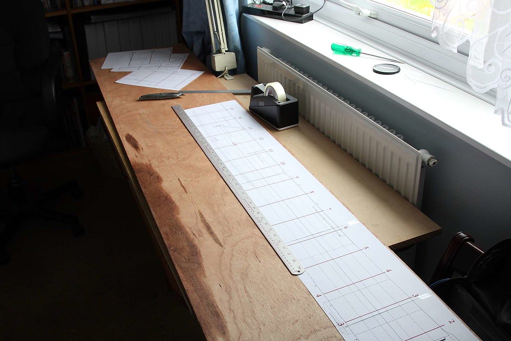
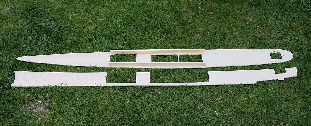
Anyway, I've begun to clean up the ones from the web, being already digitized its not hard to load into a graphics program of your choice and clean them up, scale and then print out to your desired size (limited to A3 or A4 in my case).

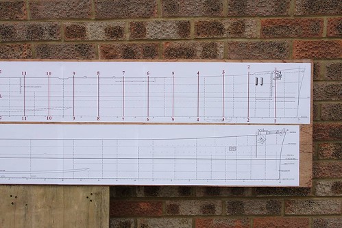
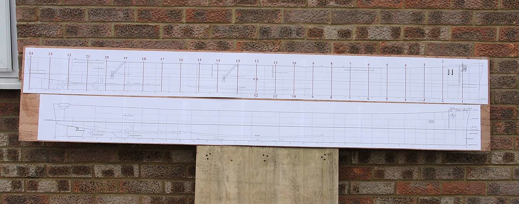
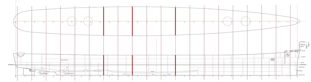
I've started with CG-11 and the side profile

Image

and have already cleaned it up, you can find a high res copy here http://homepage.ntlworld.com/mickoo/Mod ... s/CG11.jpg beware it is a very big image, I intend to do the rest of the plans (not interiors below decks...not really needed for RC models) then compile as a pdf and upload for anyone else who might be interested?.

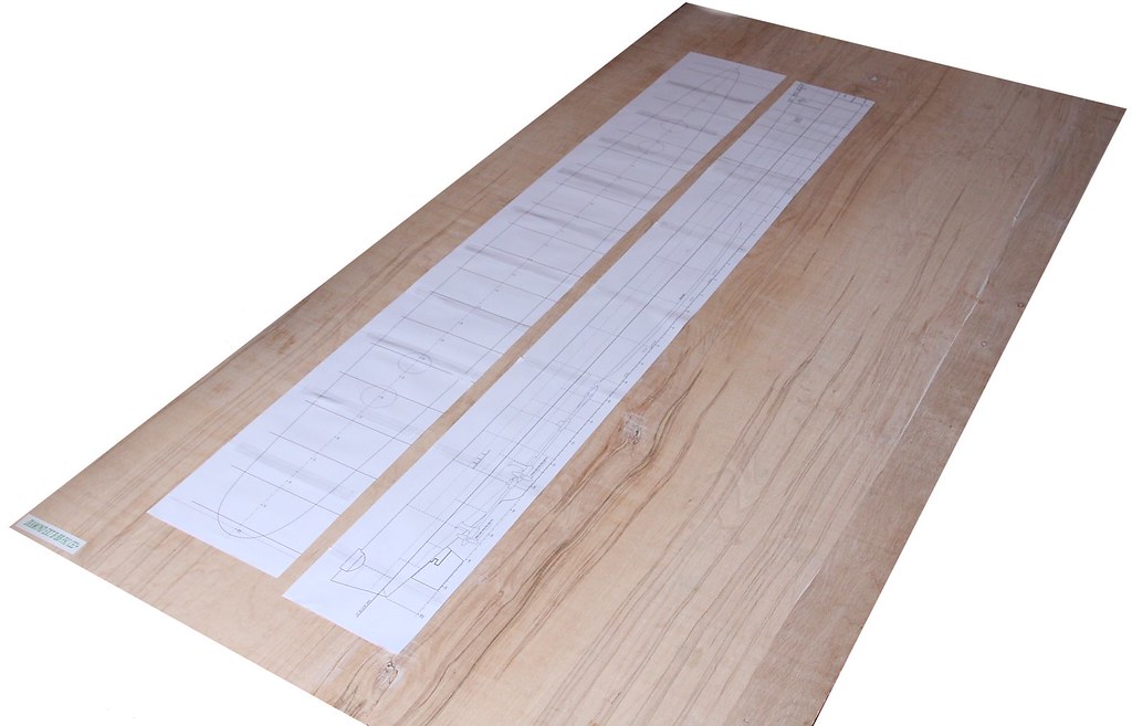
I've also cleaned the hull (only) of the CL-89, scaled and printed it out too and will do the rest of that set as above.

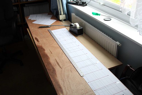
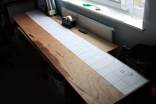
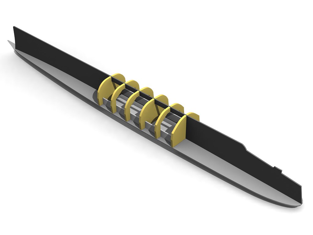
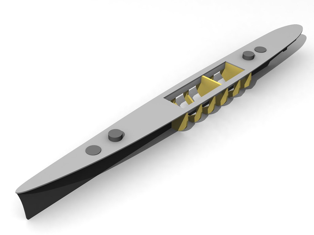
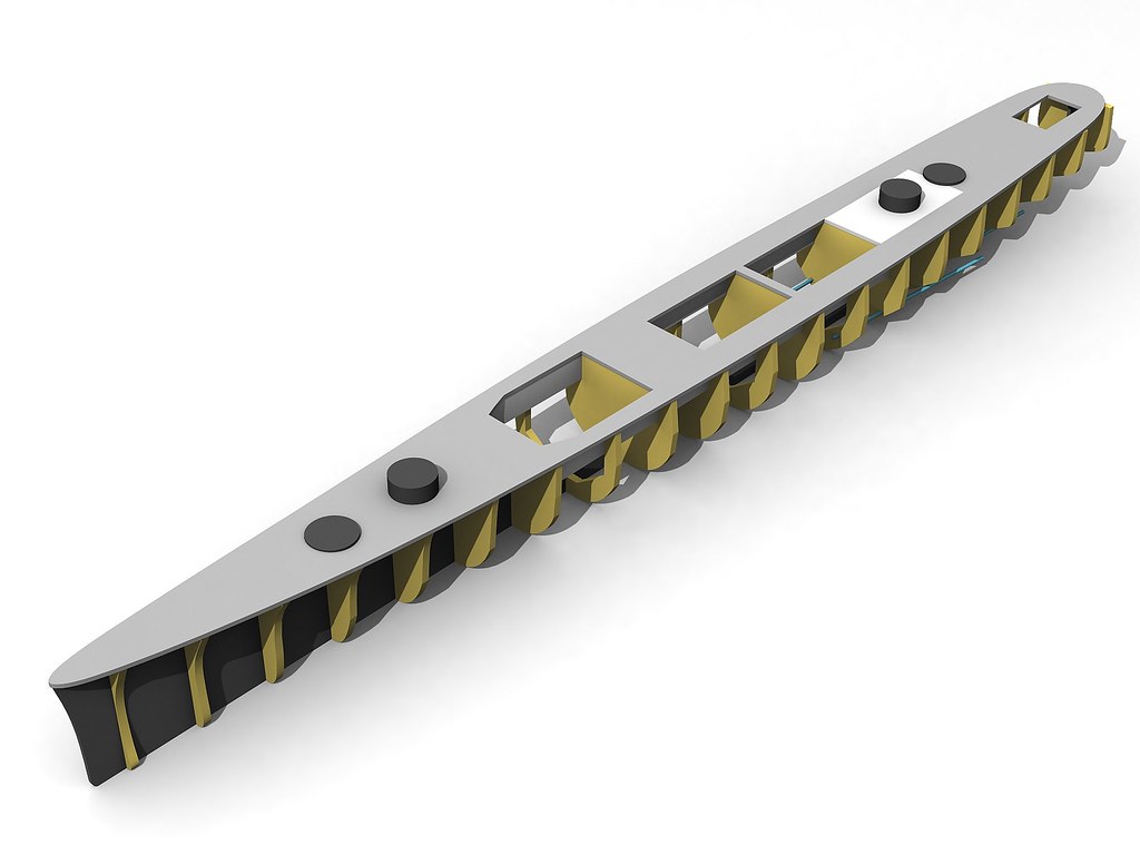
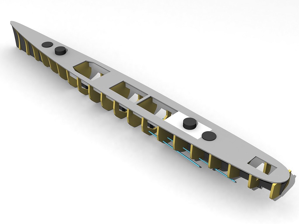
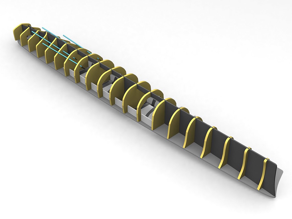
The primary purpose of printing the hull forms is to get some idea of how big these are going to be, and check the quality of my reworking. It'll also allow me to get my head around where to place frames and basic construction parts, regarding size, some how 84" looks bigger in the flesh than numbers on a jotting pad LOL, it may also prod me into a final decision as to which vessel to finally make!. I've also done some hull frames (best guess on the Baltimore's from cruiser class hull drawings already around the web) to help with frame placement and hull design.

The hull will follow what many others have already proved works, an internal skeleton skinned in thin ply/balsa, though the mid ships may vary as I've some ideas here that I want to try and simplify the framing and rigidity aspects.

Ok, so what have I actually achieved?, well I've now got two nice hull side profiles and a set of frame drawings, and if I had a decent piece of wood could probably begin to start making a mess :).

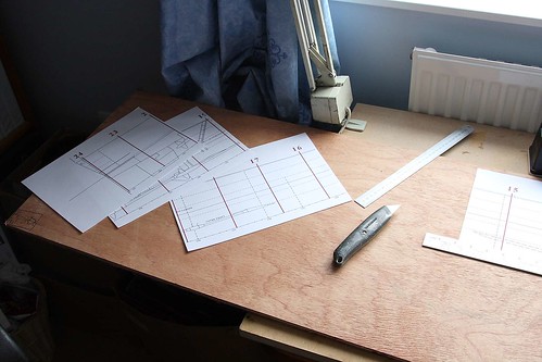
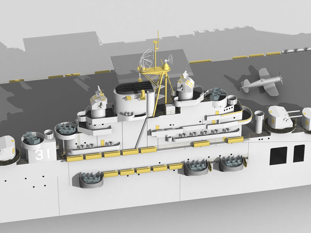
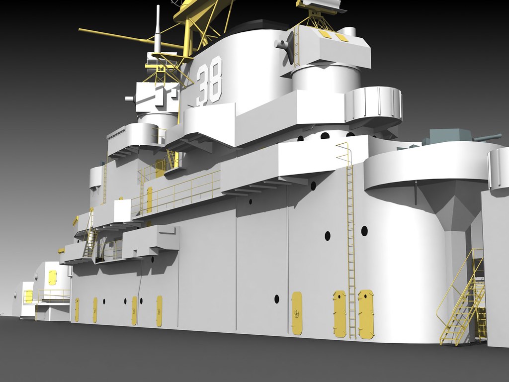
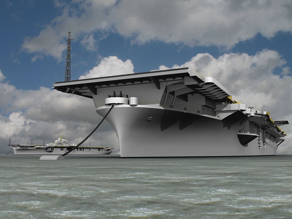
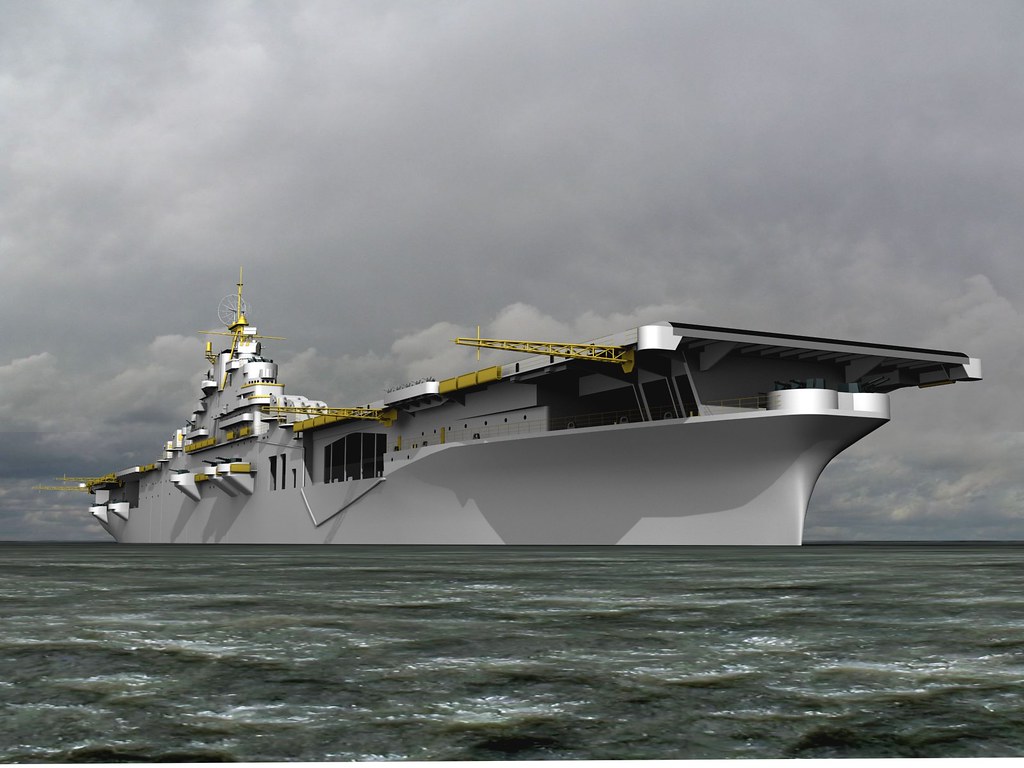
Below some images of progress so far.

Image

Image

Image

Image

Image

Image
Regarding which actual vessel will take a few more hours to decide, if I had digital plans of a WWII Baltimore like CG-11 and CV-89 then the choice would be easier, or the CAG rebuilds, then the final piece would be the non flag bridge Cleveland rebuilds.

Anyway, fire away and feel free to ask questions, when I decide the exact vessel I'll change the thread title if thats ok with the admin?, sorry its so wishy washy right now.

Kindest

Michael


Last edited by Michael Davies on Mon May 02, 2011 10:26 am, edited 11 times in total.

Report this post
Top
 Profile  
Reply with quote  
PostPosted: Sat Apr 02, 2011 2:23 pm 
Offline
User avatar

Joined: Sat Dec 09, 2006 6:12 pm
Posts: 1173
Location: campbell river.b.c canada
welcome to the scratch build board michael,lots of great builders here,one can find and get all kinds of info and advice.


Report this post
Top
 Profile  
Reply with quote  
PostPosted: Sun Apr 03, 2011 5:23 pm 
Offline

Joined: Wed Dec 12, 2007 8:24 pm
Posts: 80
Russ,

Thank you, I have been reading back through lots of threads, picking up ideas here and there, as you say, some excellent techniques and sage advice, though I'm sure I'll fall foul of something in due course LOL.

Kindest

Michael


Report this post
Top
 Profile  
Reply with quote  
PostPosted: Mon Apr 04, 2011 11:14 am 
Offline
User avatar

Joined: Tue Apr 17, 2007 9:18 am
Posts: 1979
Location: Brasil
Hi Michael very good
you are starting with great quality i can observe
let's go guy and show us what you can do
i like it :cool_1: :thumbs_up_1:


Report this post
Top
 Profile  
Reply with quote  
PostPosted: Tue Apr 05, 2011 11:55 am 
Offline

Joined: Wed Dec 12, 2007 8:24 pm
Posts: 80
Capitao Norbert,

Thank you,

Having decided on a Cleveland class hull (exact vessel and era still undecided) I could now get on with detailed plans and printing them all out and checking that all the pieces are the same size scale, oddly printers (well this one anyway LOL) adjust the scale a fraction 0.5% between landscape and portrait prints, most bizzare, none the less many printed sheets later and some sticky tape we have a side, deck elevation and frames ready for cutting out.

Now comes novice lession number 1, do not buy your new sheet of ply when its windy!, you just end up looking like some sort of demented man sail as you cross the car park!, lesson number 2, cheapest is not always best and lesson number 3, ply is often not flat. The last fact kind of scuppered my original build process, however I did find one piece that was mildly warped 13mm (1/2") over 2440mm (96") and being as I want the keel to be one piece full depth and full length (except a center dropped section, more of that crazy idea later) I don't want a banana shaped keel. The best piece I could find was 5.5mm thick so I'll probably make two keels and glue them back to back so that the warp counter acts each other and presents a dead straight keel, but that little joy comes tomorrow. The beauty of the mild warp is that it almost matches the deck profile so as a deck piece it'll drop right in with a extra little bending.

Anyway, a simple picture of the new sheet and complete deck side elevations, I'm using a new image hosting process so if anyone cannot see the pictures then let me know and I'll think of something else, just click the image for a full screen image, I've re-edited my first post as well.

Image

For the rest of this evening it'll be cutting the paper frames out and perhaps a little jaunt into Max to visualise a rough mock up of how the skeletal frame will look/work, tomorrow, weather permitting, its time to get the big cutting toys out :).

Kindest

Michael


Last edited by Michael Davies on Mon May 02, 2011 10:36 am, edited 1 time in total.

Report this post
Top
 Profile  
Reply with quote  
PostPosted: Tue Apr 05, 2011 12:39 pm 
Offline
User avatar

Joined: Sat Jan 22, 2005 10:18 am
Posts: 4131
Location: Liverpool
Hi Micheal Welcome .A very challenging start and the best of luck with your build . It looks like your off to a good start.
Dave Wooley :thumbs_up_1: :thumbs_up_1: :thumbs_up_1: :wave_1:


Report this post
Top
 Profile  
Reply with quote  
PostPosted: Tue Apr 05, 2011 1:16 pm 
Offline
User avatar

Joined: Tue Apr 17, 2007 9:18 am
Posts: 1979
Location: Brasil
when i start my first scratch model(i am doing only the second) i have many questions in mind.
how do it or that and in this time i have no acces to internet cause if i don't wrong internet was one future thing(in my time)..
now you and me can participe of this forum with many skilled modellers who learn and teach us...
force and ship ahead Michael..... :thumbs_up_1:


Report this post
Top
 Profile  
Reply with quote  
PostPosted: Tue Apr 05, 2011 6:03 pm 
Offline

Joined: Wed Dec 12, 2007 8:24 pm
Posts: 80
Gentlemen, thanks :).

Progress is chugging along, back to Max for this evenings progress, I imported the drawings and scaled them 1:1 and laid out the basic skeletal frame, already it has thrown up a couple of niggles, good thing as no wood has as yet been cut, though no doubt even all this prep work will miss something I'm sure.

Currently I envisage frames 9, 11 & 14 being solid (I had even thought of skinning them internally too) , the rest will be cut out or solid with lightening holes, however looking at the renders and the locations of the solid frame I may add another at frame 7 and open that part of the deck up as well, really not sure if the longitudinal stringers are far enough in board yet, will need to transpose the deck plan and see if the envisage deck hole is too wide. The current deck is only the skeleton and a final curved deck skin will be applied, but it would be prudent to make sure the stringers are in board enough to support the inner opening edge of the visual deck...if that makes any sort of sense. I could jog or bend the stringers to follow the deck outline but I want to keep everything on the skeleton as square and straight as possible. The other potential problem is the solid frame just where the outboard props enter the hull, that might be a good thing in that it adds support, bad in that your going to have to try and pass a prop shaft through two components in close proximity. One thing not added to the 3D keel just yet is the steering flat cut out and corresponding cut out in frame 19.

On the 1:96 model I envisage adding lightening holes to the keel outside of the center box sections, to reduce a little weight, I'm thinking. hoping! that simply cutting holes 20-50mm dia at strategic places is going to be easier then cutting internal holes with a jigsaw or scroll saw, we shall see if that idea works or falls flat on its face in days to come LOL.

Some pictures, I'll probably add the rest of the frames tomorrow between chores, just for visual reference and to keep my hand in Max, I'd not done any Max work for two months and spent a good deal of time trying to remember even the simplest of things :).

Image

Image

Image
Enjoy.

Michael


Last edited by Michael Davies on Mon May 02, 2011 10:36 am, edited 1 time in total.

Report this post
Top
 Profile  
Reply with quote  
PostPosted: Tue Apr 05, 2011 9:46 pm 
Offline
User avatar

Joined: Sat Dec 09, 2006 6:12 pm
Posts: 1173
Location: campbell river.b.c canada
hello mike,your computer work is very neat,it is somthing i would love to have the skill to do, but i have tried to work with cad programs but it is just to much for this old brain,i guess you can't teach an dog dog some things.


Report this post
Top
 Profile  
Reply with quote  
PostPosted: Wed Apr 06, 2011 1:00 am 
Offline
User avatar

Joined: Sun Mar 07, 2010 12:01 am
Posts: 1645
Location: Corvallis, Oregon, USA
Mike,

Check out my Cleveland hull at:

http://www.okieboat.com/CAD%20hull.html

Contact me through the Contact Page on my web site. I have an (almost) full set of blueprints for the Cleveland. I may be able to answer some questions.

Also, here is a link to the Cleveland hull cross-section lines, if you don't have them:

download/file.php?id=33056&mode=view

Phil

_________________
A collision at sea will ruin your entire day. Aristotle


Report this post
Top
 Profile  
Reply with quote  
PostPosted: Wed Apr 06, 2011 7:12 am 
Offline

Joined: Wed Dec 12, 2007 8:24 pm
Posts: 80
Phil,

Thanks for the frame sections, I'd already grabbed that from the Helena thread where you had kindly posted before, I'd also grabbed the booklet of plans from here http://www.hnsa.org/doc/plans/index.htm though no hull sections in that document, I scaled it to 150% in Adobe, screen grabbed sections then imported into PSP, stitched together and begun to clean them up. Generally the booklet of plans follows you hull profile until you get to the stern. I think the sterns were the same through out all vessels and all periods but I'm showing a much thinner and more rounded hull from the plans when compared with the hull sections, on my model thats frames 19 and 20.

I've looked over your site...in minute detail LOL, it is a wonder and wealth of information and data, I've shamelessly collected all your pictures and saved your pages, it is very rare to find such detailed information on the web and many thanks for sharing with the public, I tend to save web pages as I've often gone back months later and sites have gone and all that information too. To be honest, your site was the final push toward the Cleveland hull and the fact that my E books and plans from PM hadn't turned up (came last night), so the Baltimore hull will have to be my next model.

I still haven't decided on which era yet, its WWII, or a mixed armament vessel, but whether its Talos or Terrier, Flag bridge or not, has yet to be decided, though CLG-3 USS Galveston is currently top of the list as its essentially a WWII cruiser up to the first funnel then a missile cruiser from the second funnel aft, the aft structure is close to Little Rock and Oklahoma, both vessels very well documented from web pages and your information. The exact vessel isn't to much of a problem just now, as I can crack on with the hull and worry about top sides later.

I will contact you in due course and I'm sure I have many questions that only people who served might know the answers too, thank you for your offer.

Regarding your 3D model, I've modeled in CAD for 13 years now, but never to that level, always to poly limits constrained by the host sim though I did do some Essex work and posted here many years ago and the current flight sim will now accept them into the game as they stand, although as beta models. However your level is far and beyond what I ever accomplished and is excellent detailed reference work.

Kindest

Michael


Report this post
Top
 Profile  
Reply with quote  
PostPosted: Wed Apr 06, 2011 7:29 am 
Offline

Joined: Wed Dec 12, 2007 8:24 pm
Posts: 80
russclark wrote:
hello mike,your computer work is very neat,it is somthing i would love to have the skill to do, but i have tried to work with cad programs but it is just to much for this old brain,i guess you can't teach an dog dog some things.


Russ, thank you, it does take time to learn and Studio Max isn't natively intuitive, I've also got Auto cad but its impossible for me to use, I keep trying to look for the same menus and functions but each is totally different, I want to learn Auto cad so I can produce etches, not just for 1:96 ships but 'O' gauge locomotives.

I used Max almost constantly for six years but a break of just a few months and I'd already begun to forget the basics, its something you have to use almost constantly and I've found that I have too many hobbies and interests hence retirement from aircraft and sim modeling this year, my other hobbies and interests were getting way lay-ed.

3D modeling can be very helpful as Phil has already noted many times on these boards, it does take time to make the initial model, with constant references to pictures and drawings, but in the end you do have a 3D model that you can rotate and render in almost any permutation you can think off, and many you could not with a real camera.

Anyway, below a shameless plug of my 3D Essex work, a constant work in progress, 13 years in CAD and as many again before collecting info and pictures etc. The first three are straight workspace (scenes) renders, the last three are for kicks when you add an environment and begin to make pictures from them.

Image

Image

Image

Image

Image

Image

As usual, click for bigger pictures.

Kindest

Michael


Last edited by Michael Davies on Mon May 02, 2011 10:41 am, edited 1 time in total.

Report this post
Top
 Profile  
Reply with quote  
PostPosted: Wed Apr 06, 2011 10:04 am 
Offline
User avatar

Joined: Mon Jun 12, 2006 1:46 pm
Posts: 1012
Cruisers are my favorite type of warship .I will be watching this baby ! :eyes_spinning:

_________________
If you are not living on the edge then you are taking up to much space


Report this post
Top
 Profile  
Reply with quote  
PostPosted: Wed Apr 06, 2011 11:54 am 
Offline
User avatar

Joined: Sun Mar 07, 2010 12:01 am
Posts: 1645
Location: Corvallis, Oregon, USA
Michael,

Thanks. Your CAD work is very nice - you should post some of your work in the CAD section of the forum, as encouragement to other CAD modelers.

Did you use your Essex with Microsoft Flight Simulator? I used to be a flight sim nut and that model would have been terrific! The last version I used didn't have arresting cables on the carrier (off San Francisco) so the only plane that flew slow enough to land on it was the Cessna 172.

Personally, I think your level of detail is much "saner" that what I have been doing, especially for modeling. I got carried away, trying to model details down to 3/16" diameter. Someday I hope to make walk-through videos of the ship, so this small nuts and bolts detail will matter. But for 1:96 scale modeling it is a waste of time. And you wouldn't live long enough to do that kind of detail on something as large as an aircraft carrier!

I have one word of caution about the plans book drawings, and even the general arrangement and profile drawings from the blueprints. These drawings are just sketches that were used for reference so the builders had a general idea how the pieces all fit together. They are not always accurate. The hull lines I posted are essentially trace-overs from the blueprints, and I found a big mis-match (about 12 inches 1:1 scale, or 1/8 inch at 1:96) in hull breadth in the midship fore and aft section drawings. You may have to fiddle with the section lines to get a smooth hull - I did. That's why I started over working from the Table of Offsets and Shell Sight Lines. These produced a much more accurate model at the bow and stern where the hull has significant curves.

Phil

_________________
A collision at sea will ruin your entire day. Aristotle


Report this post
Top
 Profile  
Reply with quote  
PostPosted: Wed Apr 06, 2011 5:05 pm 
Offline

Joined: Wed Dec 12, 2007 8:24 pm
Posts: 80
Phil,

Yes, once I have the bulk of the Cleveland hull squared away I will head over to the CAD forum and drop a few images by for people to see.

Regarding flight sim, yes my Essex went into flight sim X the latest version with the 'Acceleration' pack allows full carrier operations, its now quite a big thing in the flight sim community, my carriers were fitted with trap wires and catapults and followed set paths so you had to go out and find them, there's my two beta Essex models for WWII and Korea and a very nice finished CVN for the more modern fans, its all terribly good fun but I found I was spending too much time in Max and not really enjoying the sim side of things, hence the change to making something tangible for a change, by rights I should be building an Essex class either WWII or Vietnam SCB125 fit, but I figured I'd start with something smaller to begin with, besides it'd have to be 1:72 so the aircraft could be nicely detailed from existing plastic kits and the CIC would not be overly impressed at a 12' model around the house, there are already 'knowing looks' when she aspies the nearly seven foot Cleveland pieces lurking around LOL.

Your bang on about the drawings, there are quite a few discrepancies, I'm reminded of one Star Trek episode where Spock has to calculate some life saving theory, only to not be able to, Capt Kirk just leans over and tells him to make his best 'guess'!, I find my self making quite a few 'best' guesses :). I work with and around marine vessels full time and know that the hull form is usually pretty free flowing so its not hard to pick out the best shape it should have from a nautical perspective and then round out any lumps and bumps.

I've finished my 3D CAD model and it quite clearly shows issues with the frames 18-19 and 20, they look more to be from a Baltimore with the two aircraft cranes, these frame stations are lifted from your plan so I'm not sure what is really going on, I'm inclined to think your plan is more accurate than the deck shape from the booklet of plans, it may be that the frame spacing on your hull sections is reduced in this area, instead of my standard spacing through out the hull length, my best guess is that these frames need shunting forward slightly, narrowing a Little and the deck expanding out, I'm going to go over my Cleveland hull images tomorrow and see if I can get a better perspective on the aft deck shape.

The CAD model has shown up one little niggle, my main deck is about 15" too high, in model form thats about 4mm on the 1:96 model, I can either ignore this or redraw the plans with the keel a little lower so that the main deck sits at the right height, its currently a 2.8% error. I've added in the prop tubes which is helpful as it already shows that the outer shafts are going to be tight for motor placement, the lighter aft deck component is the deck area that can and will be removed if the model ends up as a CLG (highly probable) model.

Anyway the pictures

Image

Image

Image

Image
Enjoy

Michael


Last edited by Michael Davies on Mon May 02, 2011 10:45 am, edited 1 time in total.

Report this post
Top
 Profile  
Reply with quote  
PostPosted: Fri Apr 08, 2011 12:08 am 
Offline
User avatar

Joined: Sun Mar 07, 2010 12:01 am
Posts: 1645
Location: Corvallis, Oregon, USA
Michael,

The hull lines drawing I posted is of the "Stations" - spacing between Stations was 15 feet. These are the original first guess calculations for the hull. There were 40 stations (600 feet) between the "perpendiculars" or the "Fore Peak" (FP) and "Aft Peak" (AP). These were places at the bow and stern at the full load waterline. The hull actually extended forward of the Fore Peak and aft of the Aft Peak a bit, so it was 610 feet over all. I did find several of the station lines about where the props were to be a little bit squrrely. Lines based upon the Table of Offsets were much better.

Later the actual frame lines were calculated for the construction of the ship. The 150 frames were at 4 foot spacing. Below the waterline were an additional 149 half frames positioned intermediate between the frames.

The stern was more or less semicircular at the main deck and squared off at the bottom of the "transom." This created some pretty complex curved surfaces, and was far and away the hardest part to get right. The station lines are spaced much too far apart to get the right curvature. I ended up using the "Tables of Hull Sight Lines" (survey data for the top and bottom edges of the plating strakes) to figure out the shape.

I have a good PDF drawing of the hull lines (profile, plan view, station lines, frame lines, stem stern, bilge keel, rudder and skeg, propeller shafts and struts, etc.) that you are welcome to. It is a composite drawing based upon 14 of the original blueprints, scaled at 1:96 to print on a 36" x 84" sheet. File size is 2 Mbytes (too big to post here). The station lines are a part of this larger drawing.

Contact me through this page and I'll send it to you:

http://www.okieboat.com/Contact%20page.html

Phil

_________________
A collision at sea will ruin your entire day. Aristotle


Report this post
Top
 Profile  
Reply with quote  
PostPosted: Fri Apr 08, 2011 4:23 am 
Offline

Joined: Wed Dec 12, 2007 8:24 pm
Posts: 80
DrPR wrote:
Michael,

The hull lines drawing I posted is of the "Stations" - spacing between Stations was 15 feet. These are the original first guess calculations for the hull. There were 40 stations (600 feet) between the "perpendiculars" or the "Fore Peak" (FP) and "Aft Peak" (AP). These were places at the bow and stern at the full load waterline. The hull actually extended forward of the Fore Peak and aft of the Aft Peak a bit, so it was 610 feet over all. I did find several of the station lines about where the props were to be a little bit squrrely. Lines based upon the Table of Offsets were much better.

Later the actual frame lines were calculated for the construction of the ship. The 150 frames were at 4 foot spacing. Below the waterline were an additional 149 half frames positioned intermediate between the frames.

The stern was more or less semicircular at the main deck and squared off at the bottom of the "transom." This created some pretty complex curved surfaces, and was far and away the hardest part to get right. The station lines are spaced much too far apart to get the right curvature. I ended up using the "Tables of Hull Sight Lines" (survey data for the top and bottom edges of the plating strakes) to figure out the shape.

I have a good PDF drawing of the hull lines (profile, plan view, station lines, frame lines, stem stern, bilge keel, rudder and skeg, propeller shafts and struts, etc.) that you are welcome to. It is a composite drawing based upon 14 of the original blueprints, scaled at 1:96 to print on a 36" x 84" sheet. File size is 2 Mbytes (too big to post here). The station lines are a part of this larger drawing.

Contact me through this page and I'll send it to you:

http://www.okieboat.com/Contact%20page.html

Phil


Phil,

You are quite right, the stern section on the booklet of plans is way off, much much too rounded, I used your stations drawing, transposed the data to the deck and redrew the rear to suit, printed out and attached to the master deck drawing.

I went back over everything last night and double checked and am just about ready to cut wood, even cut out all the frame sections ready for transfering to wood, however, your gift of a pdf set of more authentic drawings would be fantastic and elevate the model from just about right-ish (+-2%) to very accurate. I have to confess I'm a bit of a technophile when it comes to drawings LOL, either marine or railway, you can just never have enough drawings :). I was actually going to ask this morning if you knew the correct width of the skeg, that'll determine whether I need to use one keel section at 5.5mm width or laminate as originally planned at 11mm. I dont have a printer that'll print that large but I can scale and then print sections on A4 and stitch together, once you know one accurate dimension on the drawing its not too difficult to scale and print, once I have those I can collect all the A4 drawings and set them in there own pdf, send to you, so others in the future can also print off the hull from a household printer if they wish.

Kindest regards

Michael


Report this post
Top
 Profile  
Reply with quote  
PostPosted: Sat Apr 09, 2011 12:48 pm 
Offline

Joined: Wed Dec 12, 2007 8:24 pm
Posts: 80
Ok, small update, after some excellent reference from Phil the final hull shape has been defined and wood has been cut. The deck and full depth keel are 5.5mm (7/32) ply, I've yet to cut the notches for the frames 9mm (11/32?) but hopefully weather permitting that will be done tomorrow. The deck is done and needs the longitdual stringers attaching, that'll be done over night so I they are good and firm for tomorrow.

Image

Kindest

Michael


Last edited by Michael Davies on Mon May 02, 2011 10:45 am, edited 1 time in total.

Report this post
Top
 Profile  
Reply with quote  
PostPosted: Sat Apr 09, 2011 4:33 pm 
Offline
User avatar

Joined: Mon Jan 10, 2005 10:52 am
Posts: 2557
Location: Land of the Cheshire cat
Looking good Michael , :thumbs_up_1: :thumbs_up_1: :wave_1:

_________________
Simple but effective.


Report this post
Top
 Profile  
Reply with quote  
PostPosted: Sat Apr 09, 2011 5:30 pm 
Offline

Joined: Wed Dec 12, 2007 8:24 pm
Posts: 80
ARH wrote:
Looking good Michael , :thumbs_up_1: :thumbs_up_1: :wave_1:


Thank you, long way to go before I get to your level :), both productivity and skill wise LOL, I do like your large double skinned area idea on your Helena, the Cleveland's have two knuckles and the skin between them is pretty flat in the horizontal plane which suits the large skin application technique.

Kindest

Michael


Report this post
Top
 Profile  
Reply with quote  
Display posts from previous:  Sort by  
Post new topic Reply to topic  [ 97 posts ]  Go to page 1, 2, 3, 4, 5  Next

All times are UTC - 6 hours [ DST ]


Who is online

Users browsing this forum: No registered users and 17 guests


You can post new topics in this forum
You can reply to topics in this forum
You cannot edit your posts in this forum
You cannot delete your posts in this forum
You cannot post attachments in this forum

Jump to:  
Powered by phpBB® Forum Software © phpBB Group