The Ship Model Forum

The Ship Modelers Source
It is currently Tue Jul 22, 2025 5:26 am

All times are UTC - 6 hours [ DST ]


Post new topic Reply to topic  [ 191 posts ]  Go to page Previous  1, 2, 3, 4, 5 ... 10  Next
Author Message
PostPosted: Thu Aug 04, 2011 6:22 pm 
Offline

Joined: Thu Jul 07, 2011 5:12 pm
Posts: 296
Also, according to the Warship Profile book #36, the 15in. gun (compared to the 11in.) was initially shorter, so when moved forward, it wouldn't fully protrude from the turret, that was later changed by extending the barrel. Another thing that changed was the port stoppers, from pendulum type to crank-shaped forgings, allowing both guns to be fired together.

Here's a partial pic of that.


Attachments:
Forged port stoppers.gif
Forged port stoppers.gif [ 89.11 KiB | Viewed 1405 times ]
Report this post
Top
 Profile  
Reply with quote  
PostPosted: Thu Aug 04, 2011 7:33 pm 
Offline
User avatar

Joined: Sat Jun 11, 2011 5:02 pm
Posts: 275
Thanks for clearing that up. Would the Tecumseh have had those longer guns? If anyone else sees anything that needs changing, then please let me know.

Devin: I loved your Weehawken. It's one of the things that got me thinking of doing a monitor. As to the hull, I couldn't find any definitive sources on how the angle tapered into the stern post, I've had to wing some of it.

Worked on placing the deck vents. Also worked on the anchor. All the ref I have, and the photos, show that they had to change the design from the 'in bow' anchor to more conventional external ones. I've seen one set of blueprints that have the anchor well style of the Monitor and Passaic class, but nothing else corroborates this.

Here's the anchor. I've based it off this account, specifically this anchor:

Image
This matches the photos of the Mahopac nicely.
Attachment:
mahopac1b_web.jpg
mahopac1b_web.jpg [ 52.97 KiB | Viewed 1203 times ]


Tomorrow the boats!


Last edited by tea monster on Sun Sep 25, 2011 5:44 pm, edited 1 time in total.

Report this post
Top
 Profile  
Reply with quote  
PostPosted: Thu Aug 04, 2011 9:23 pm 
Offline
User avatar

Joined: Mon Jan 10, 2005 10:46 am
Posts: 2467
Location: Hoboken, NJ
Wow, thanks for the compliment. That made my day!

I've got a set of plans in PDF format that I think are from when they surveyed the wreck in the '60's with intent on raising Tecumseh. They may be what you have, or may not. I got them from Brad Chaucer just a few weeks before he passed away, so I'm not totally sure as to their source. PM me if you would like a copy of them, I can zip them up and put them in a download location for you, a Zip file of all 5 PDFs is nearly 500 megs in size.

_________________
We like our history sanitized and theme-parked and self-congratulatory, not bloody and angry and unflattering. - Jonathan Yardley


Report this post
Top
 Profile  
Reply with quote  
PostPosted: Thu Aug 04, 2011 10:52 pm 
Offline

Joined: Thu Jul 07, 2011 5:12 pm
Posts: 296
tea monster wrote:
Would the Tecumseh have had those longer guns?

Yes, I believe they were the longer 15in. guns.

A bit OT, but I agree, Devin's model is a real beauty...

Dean
( Trying not to be a post hog. )


Report this post
Top
 Profile  
Reply with quote  
PostPosted: Sat Aug 06, 2011 11:01 am 
Offline
User avatar

Joined: Sat Jun 11, 2011 5:02 pm
Posts: 275
Many, many thanks to everyone who has forwarded plans and information to me!

I've got to take stock and revamp things according to the new info, so I'll put up some shots in the next day or two after I've adjusted a few things.

Thanks again.


Report this post
Top
 Profile  
Reply with quote  
PostPosted: Mon Aug 08, 2011 3:08 pm 
Offline
User avatar

Joined: Sat Jun 11, 2011 5:02 pm
Posts: 275
Got some more work done. I've blocked out a lot of the deck items. Got a shell of the boats done.

I went over the plans and the new info that people have sent and I've confirmed that everything is accurate as can be.

Attachment:
sideplan.jpg
sideplan.jpg [ 84.51 KiB | Viewed 1203 times ]


Still adjusting stuff and creating things. The new info has been invaluable for the deck and hull layout. Once I've got all the major parts in place, I'll do few 'detail passes' and put in rivets and other errata. The hull plates are going to be done with bump maps.

Attachment:
render15.jpg
render15.jpg [ 32.81 KiB | Viewed 1203 times ]

Attachment:
render16.jpg
render16.jpg [ 28.23 KiB | Viewed 1203 times ]


Last edited by tea monster on Sun Sep 25, 2011 5:56 pm, edited 1 time in total.

Report this post
Top
 Profile  
Reply with quote  
PostPosted: Mon Aug 08, 2011 3:11 pm 
Offline
User avatar

Joined: Mon Jan 10, 2005 10:46 am
Posts: 2467
Location: Hoboken, NJ
Wow, that looks amazing! Makes me want to build one!

_________________
We like our history sanitized and theme-parked and self-congratulatory, not bloody and angry and unflattering. - Jonathan Yardley


Report this post
Top
 Profile  
Reply with quote  
PostPosted: Mon Aug 08, 2011 5:42 pm 
Offline

Joined: Thu Jul 07, 2011 5:12 pm
Posts: 296
Looks Great!!! really nice work on the details.


Report this post
Top
 Profile  
Reply with quote  
PostPosted: Mon Aug 08, 2011 8:04 pm 
Offline

Joined: Thu Apr 28, 2005 8:46 pm
Posts: 201
Owen -- well on your way to a masterpiece. Superfine. Michael


Report this post
Top
 Profile  
Reply with quote  
PostPosted: Thu Aug 11, 2011 4:27 pm 
Offline
User avatar

Joined: Sat Jun 11, 2011 5:02 pm
Posts: 275
Thanks very much! I'm really enjoying this one. It's great to see it coming together.

Work progressing.

Got to say, these are NOT the completed textures or lighting. It's just a test for visibility. Just about all the parts are in place. It's just going through and adding details. The anchors need changing and there are some sniper holes to cut in the bullet shield.

Attachment:
YAF6.jpg
YAF6.jpg [ 77.42 KiB | Viewed 1203 times ]


Last edited by tea monster on Sun Sep 25, 2011 6:01 pm, edited 1 time in total.

Report this post
Top
 Profile  
Reply with quote  
PostPosted: Thu Aug 11, 2011 6:34 pm 
Offline
User avatar

Joined: Mon Jan 10, 2005 10:46 am
Posts: 2467
Location: Hoboken, NJ
Huh, I never realized how those anchors were mounted. I thought there would be a single that dropped from an anchor well forward, as on the Passaic class.

Fantastic work, by the way!

_________________
We like our history sanitized and theme-parked and self-congratulatory, not bloody and angry and unflattering. - Jonathan Yardley


Report this post
Top
 Profile  
Reply with quote  
PostPosted: Thu Aug 11, 2011 9:57 pm 
Offline

Joined: Thu Jul 07, 2011 5:12 pm
Posts: 296
It never ceases to amaze me what a few textures can do, superb work Owen,
looking forward to the finale.

Dean


Report this post
Top
 Profile  
Reply with quote  
PostPosted: Fri Aug 12, 2011 12:23 am 
Offline
User avatar

Joined: Sun Mar 07, 2010 12:01 am
Posts: 1677
Location: Corvallis, Oregon, USA
This is looking very nice.

Can Blender import files from other programs?

What is the maximum file size limit with Blender?

What is your opinion of the user interface in Blender? Is it easy to use or do the commands work in nonintuitive ways?

How long did it take to render your images? How many polygons or solids are in your drawing?

Phil

_________________
A collision at sea will ruin your entire day. Aristotle


Report this post
Top
 Profile  
Reply with quote  
PostPosted: Fri Aug 12, 2011 3:16 pm 
Offline
User avatar

Joined: Sat Jun 11, 2011 5:02 pm
Posts: 275
Thank you very much! I'm trying my best to make this as accurate as possible.

Latest render - bullet shield complete, vent and stack complete, deck gubbins nearly complete. Hull revamped.
Again, these are NOT final mats.
Attachment:
YAF7a.jpg
YAF7a.jpg [ 71.82 KiB | Viewed 1203 times ]


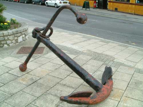
Devin - The sharper bow precluded the more traditional Monitor-style anchor-well. I think the first ship was already built when they finally agreed on a new way of doing it. The Windlass is farther back than the other Monitors and two separate anchor chains - port and starboard - go up and over the deck under those bolt-festooned covers. From the look of the drawings that I have, it looks like the anchor chain exits under the overhang and the anchors hang down on either side of the bow of the ship. On photos of the Mahopac and other monitors, the anchors are usually seen hoisted out of the water and stowed on deck.

Roscoe - Cheers! So am I!

DrPR - Taking your questions in order...

1. Yep. Not directly, but it imports standard formats like .obj, .dae, Collada, FBX etc. If you wanted to get a file from Max to Blender, you'd just export from Max as one of the standard formats and import that into Blender.

2. Depends on memory and machine. I've got a quad core Phenom with 4 Gb of RAM and I can handle a three or four million Polygons before it starts to get chuggy. The current Blender dosen't like large Obj files. It takes about 5 minutes or more to load a high-poly z-brush sculpt. But once its in, Blender can work with it.

3. I personally much prefer the new interface, it's much more like a 'regular' application. A few old-hands like the old one as everything is to hand, but that creates the 'Space Shuttle Control Panel Effect' which can send new users screaming for the hills. The new interface is much cleaner and looks more modern. I usually use command-keys anyway though and only hunt for buttons occasionally. The big thing with Blender is that it dosen't follow standard command key conventions - even the mouse selects with the right button, rather than the left. But once you start using it, it falls into place pretty easily. They do have a keyboard shortcut remapping feature that will re-map your shortcut keys to Maya norms, and I'm pretty sure other standards will follow shortly. This is what my screen looks like:

Attachment:
tecumsehscreen.jpg
tecumsehscreen.jpg [ 76.96 KiB | Viewed 1203 times ]

4(a). First off, I'm using a third-party raytracer called 'Yafaray'. It's free and open source. I like to ray-trace my presentation clays, so they take about 10-15 minutes to render usually. It's possible to set up spots and hemi's without raytracing in Blender's internal renderer and get a reasonable render out in a minute or two. I just like ray-tracing! There is also a very good OpenGL renderer that can be used for animations and previewing textures and render settings. Blender's internal renderer is OK for basic stuff, and it looks alright if you use HDR environments, but it can't do real GI or bounces. There are a load of 3rd party renderers though, there is even a V-Ray pipeline.

The last few images took between 20 - 30 minutes. Pathtracing with 6 bounces and 32 path samples. The first image uses a studio light set-up with 2 plane emitters and the second a sun lamp and a generated sky environment.

4(b). 140,000 polys (counting smooth modifiers) and 115 objects.

The big problems with Blender are its modelling tools and it's renderer. Currently they are working on both of these but they are about 3 to 6 months away.


Last edited by tea monster on Sun Sep 25, 2011 6:06 pm, edited 1 time in total.

Report this post
Top
 Profile  
Reply with quote  
PostPosted: Fri Aug 12, 2011 3:34 pm 
Offline
Site Admin
Site Admin
User avatar

Joined: Sat Jan 08, 2005 4:31 pm
Posts: 3579
Location: Plattsburg, Missouri
Very nice rendering. I love the waterline look!

_________________
Timothy Dike
Owner & Administrator
ModelWarships.com


Report this post
Top
 Profile  
Reply with quote  
PostPosted: Fri Aug 12, 2011 10:08 pm 
Offline
User avatar

Joined: Mon Jan 10, 2005 10:46 am
Posts: 2467
Location: Hoboken, NJ
That looks amazing!

I noticed in the line drawing (not sure if that's the correct terminology) the full guns are visible. Are you detailing the turret interior as well?

_________________
We like our history sanitized and theme-parked and self-congratulatory, not bloody and angry and unflattering. - Jonathan Yardley


Report this post
Top
 Profile  
Reply with quote  
PostPosted: Sat Aug 13, 2011 3:00 am 
Offline
User avatar

Joined: Sun Mar 07, 2010 12:01 am
Posts: 1677
Location: Corvallis, Oregon, USA
Thanks.

I come from a more traditional CAD background and none of the file types you mention are familiar. DWG, IGES and STEP are the most common file transfer formats.

I was interested in Blender as a possible way to create more realistic renderings of the CAD model I am working on. You have given me the information I was seeking.

For comparison, one (of three) of the deck houses on the cruiser I am working on has about 800,000 objects, with 440,000 solids and 350,000 planes. I have no idea what the total polygon count is. It takes about 90 minutes for the first rendering (simple directional lighting with shadows and material properties) of the deck house, but after that I can generate new images with different rotations and perspectives in about 10 minutes. The whole ship must be several million objects (I have never totalled them). The last time I rendered the entire ship it took about two hours (that was two years and a lot fewer details ago).

If 115 objects with 140,000 polygons take 20-30 minutes for ray tracing, I doubt I will live long enough to ray trace my model.

Phil

_________________
A collision at sea will ruin your entire day. Aristotle


Report this post
Top
 Profile  
Reply with quote  
PostPosted: Sat Aug 13, 2011 7:03 am 
Offline
User avatar

Joined: Sat Jun 11, 2011 5:02 pm
Posts: 275
Thank you!

Devin - I'll probably do the carriages and guns, but I don't have any plans to do interiors. I could consider a turret interior. I currently don't have enough info to do an interior of the hull justice - besides which, it would be a 'heu-riffy-cally' involved job.

DrPR - Ouch! Blender does read DXF files, which are what architecural vis artists have been traditionally reading into Blender to render house plans. If that failed, there is a util called QCAD which supposedly can act as a go-between from one of the file formats you mentioned and DXF.

Though I like raytracing, I recently did a quick render of the ship, with just spot lights and hemis and no environment or AO and I got a render in 21 seconds. There are 'fake' AO settings and environment lighting settings - if you fiddle with it, you can get something that looks really tight and can render in seconds.

If you want a general render, there is the OpenGL viewport, which produces a good visualisation in real time.

If you can kick out a DXF test file, I don't mind trying to import it. PM me with details.


Report this post
Top
 Profile  
Reply with quote  
PostPosted: Sat Aug 13, 2011 11:11 am 
Offline
Site Admin
Site Admin
User avatar

Joined: Sat Jan 08, 2005 4:31 pm
Posts: 3579
Location: Plattsburg, Missouri
Devin wrote:
I noticed in the line drawing (not sure if that's the correct terminology)


FYI That is called the wire frame drawing.

_________________
Timothy Dike
Owner & Administrator
ModelWarships.com


Report this post
Top
 Profile  
Reply with quote  
PostPosted: Sat Aug 13, 2011 11:43 am 
Offline
User avatar

Joined: Mon Jan 10, 2005 10:46 am
Posts: 2467
Location: Hoboken, NJ
Cadman wrote:
Devin wrote:
I noticed in the line drawing (not sure if that's the correct terminology)


FYI That is called the wire frame drawing.


Ah, thanks. I think when I last took a CAD class in the early 90's they called it vector based or something.

_________________
We like our history sanitized and theme-parked and self-congratulatory, not bloody and angry and unflattering. - Jonathan Yardley


Report this post
Top
 Profile  
Reply with quote  
Display posts from previous:  Sort by  
Post new topic Reply to topic  [ 191 posts ]  Go to page Previous  1, 2, 3, 4, 5 ... 10  Next

All times are UTC - 6 hours [ DST ]


Who is online

Users browsing this forum: No registered users and 10 guests


You can post new topics in this forum
You can reply to topics in this forum
You cannot edit your posts in this forum
You cannot delete your posts in this forum
You cannot post attachments in this forum

Jump to:  
Powered by phpBB® Forum Software © phpBB Group