I have been asked by Pavel, of Admiralty Model Works, to design a model of USCGC Bertholf (WMSL-750) for use in future model kits. I agreed to do it in exchange for him printing my personal 3D parts.
I should perhaps first say that I am by no means an expert in CAD solid modeling, although I have been using AutoCad for several years (since AutoCad 9, that was on several of those old 5-1/2� floppy disks) for doing my site and project layouts in 2D, and am currently using AutoCad Civil3D. The modeling I am doing is not intended to create beautiful, well rendered and textured virtual models, but rather to create models that can be effectively exported to STL files for 3D printing.
The first model I did was a 1/144 scale USS Greenling (SSN-614).
viewtopic.php?f=59&t=125875
Actually, it was (or will be) two models, as I first made one with no details, then later added a lot of detail to make another. The CAD work on both models is complete. The non-detailed version is mostly built, but awaiting printing of a couple of fairings I decided to add to give it at least some detail. The detailed version is waiting for printing as well.
My second (or third) CAD model is a 1/144 scale USS Batfish (SS-310), that I am currently working on.
http://www.subcommittee.com/phpBB3/view ... 35&t=11415
Pavel, upon seeing these build threads, contacted me, and here we are.
So far, I have designed 3 small items for Pavel and AMW, all intended for production at both 1/350 scale and 1/700 scale. The items include:
A Goalkeeper CIWS � viewtopic.php?f=27&t=152674
A Tilly Crane for WW2 Carriers - viewtopic.php?f=2&t=152775
A Moto Tug for WW2 Carriers - viewtopic.php?f=2&t=152798
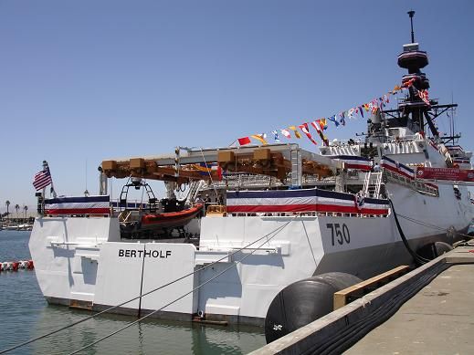
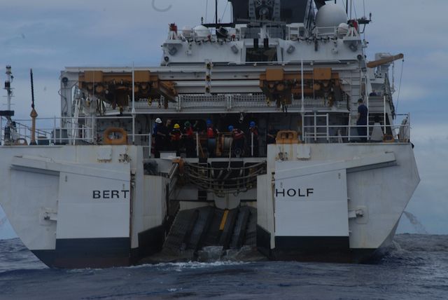
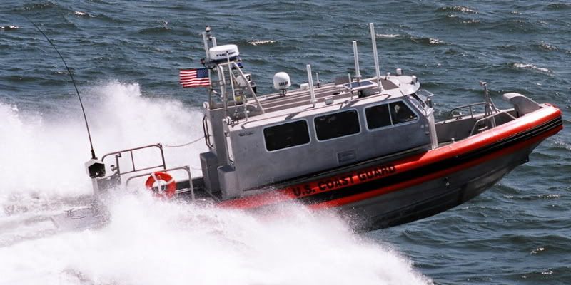
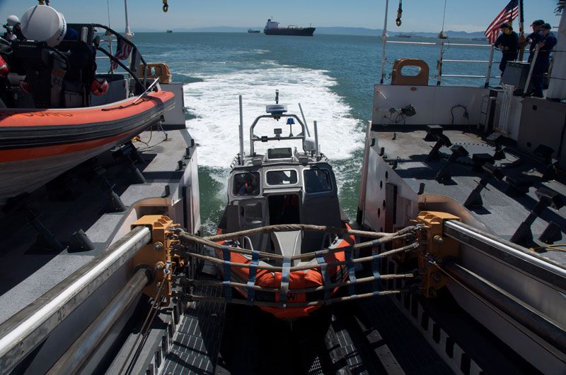
USCGC Bertholf, a modern Coast Guard cutter, will be my first major undertaking for AMW. It too is being planned for release in both 1/350 and 1/700 scales, and will be designed so that the kit, when released, can be assembled full ship or waterline. Here are a couple of pictures of this attractive ship.


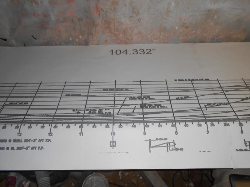
Before I started this project, I was provided a decent (but not great) set of plans and a lot of excellent pictures. The plans did include a good sheet of �Hull Line Plans�, so that is where I began.
If you haven�t seen hull line plans before they typically show cross sections at various �frames� along the hull. Sections for the forward half of the ship are on one side and sections for the aft half of the ship are on the other side. In the image below, I have traced the forward sections, which for the Bertholf plans, is on the right side (this may be typical, I don�t know). I have mirrored the sections to the other side. (Note: All plans were imported and scaled to real size.)

I then connected the individual sections with lines at the top and then combined the three parts of each section into a polyline, which I then moved to the proper location along the hull axis.

I then did the same with the aft half�


�And then lofted the sections together.


For the most part it looks pretty good, but for the first cut, I was a little delinquent in using guidelines, which improve the accuracy of the loft, but take longer to do. The aft and mid-sections looked good, but not parts of the forward section. I would fix that later, but first I did the bow, which was not included in the frame sections. Instead, I had to use another section of the plan sheet, where the �Waterlines� are shown.
The image below shows the tracings of the bow section. Note that due to symmetry, the waterlines are only shown for half of the ship, so like I did with the sections, I traced the waterlines, mirrored them, joined the ends and turned them into polylines.

I then changed the elevation of each waterline as specified on the plans and lofted them, this time using guidelines to improve the quality of the loft.


Because of the way the plans are laid out, I had to rotate the bow section�

�Before moving it into the proper position.

After that, I fixed the issues with the hull, adding the guidelines I neglected the first time.


?
Being satisfied with the hull, I moved top side, using the Outboard Profile plan sheet to trace the major structures, and stern cut out section on the ship, then copied them to the model. (Note the horizontal and vertical reference lines.)

Because the copied sections were in the middle of the ship, I had to move them outboard before I could extrude them.

I started by extruding the stern cut out�

�And subtracting it.

Next I extruded the shapes that spanned the width of the ship, including the curved parts at the bottom of the structures.

You may have noticed the blue angled lines at the aft end of the ship. These lines are parallel and even with the face on the hull. I next extruded the line on the starboard side�

�And used it to slice off the unwanted parts of the lofted shapes. (In hindsight, I could have done this using the line, without extruding it to create a surface.)

I then did the same for the port side.


Note that even though I recolored everything gray, the pieces have not been joined. This is especially important for the curved sections at the bottom of the structures, which do not extend the width of the ship, but only extend as wide as the bulwarks are, so I will need to slice them later.
I hope you enjoyed this post, and I will continue posting my progress as I go. If at any point you see something wrong, please don�t hesitate to point it out to me. The main reason I post my builds (on AutoCAD, or for real) is to get feedback from people more knowledgeable than myself.
CHEERS!!!