The Ship Model Forum

The Ship Modelers Source
It is currently Thu Apr 18, 2024 1:01 am

All times are UTC - 6 hours [ DST ]


Post new topic Reply to topic  [ 22 posts ]  Go to page 1, 2  Next
Author Message
PostPosted: Mon Dec 31, 2018 5:44 am 
Offline

Joined: Wed Mar 09, 2016 5:17 am
Posts: 59
Am on the home run of completing 1:400 cruiser Aurora. This is the recent iteration by ARK Models which reboxed this old old plastic kit with a small detail set of resin and photoetch to modify the ship to its 1917 appearance. It's been a trying build and I could write a page on the instruction discrepancies, missing parts and other fails that ARK did. But that's for another time.

So on the Aurora, in all its versions, the smokestacks stand basically where the bridge ends. This kit though, the bridge ends and there's a very large obvious gap until the first smokestack. And it's empty. I don't know why - either the bridge begins too early, or the bridge is too small, or the whole damn deck is completely wrong. I call this gap, 'the abyss'. There are no parts in the kit that go here - as you can see from the ARK Models photo, they just...expect you to build the kit like so, and try to ignore the fact there's an abyss between the funnel and bridge.

When completed, this ship is going to look very awkward and unhistorical like that. There should be no such gap between the smokestack and bridge. If I try to scratch build some sort of cover for the abyss and paint over it, it doesn't change the fact that this gap shouldn't exist in the first place. And I've already finished building and painting my bridge to think about modifying that.

What would you do? Continue to finish the model and just accept the fact that as far as historical accuracy is concerned it's a write-off? Or touch it up and disguise it somehow?


Attachments:
File comment: Aurora aerial view. In all her career, the smokestacks are directly behind the bridge. Not separated by a football field.
240_F_164361981_udw8kTq2nyv6rPyevbP8SH6nzc0uIFO3.jpg
240_F_164361981_udw8kTq2nyv6rPyevbP8SH6nzc0uIFO3.jpg [ 22.53 KiB | Viewed 3409 times ]
File comment: Official by ARK Models, showing completed model unpainted, to showcase their resin and PE additions
113_5284.JPG
113_5284.JPG [ 369.69 KiB | Viewed 3409 times ]
File comment: THE ABYSS
IMG_20181231_181818.jpg
IMG_20181231_181818.jpg [ 310.56 KiB | Viewed 3409 times ]
Top
 Profile  
Reply with quote  
PostPosted: Mon Dec 31, 2018 10:49 am 
Offline

Joined: Sun Aug 20, 2017 9:46 am
Posts: 1439
Location: Montreal, Canada
Well...it's too late to reposition the funnels and space them out . It's also too late to cut the hull and shorten it where the discrepancy is. I would just deck it over and add some PE W/T doors on the bulkheads, and try to pretend there's no problem. Maybe add some railings and a ladder and other detail. Did the original company fudge the dimensions and make the hull too long?
:wave_1:


Top
 Profile  
Reply with quote  
PostPosted: Mon Dec 31, 2018 2:30 pm 
Offline
User avatar

Joined: Mon Jan 10, 2005 6:00 pm
Posts: 12143
Location: Ottawa, Canada
This beam-on image seems to illustrate well the problem: https://www.flickr.com/photos/kev_grego ... 487103925/

Seems you can shuffle all three funnels forward a bit: the third funnel to where the forward davit is, the second funnel to just slightly forward of the third gun, and the first funnel so that its aft cowl vent is even with the second gun. It'd probably require some scratchbuilding to fix the levels on that superstructure they're sitting on, but shouldn't be too much work (though you already have the wood decking on, so that's unfortunate).

_________________
De quoi s'agit-il?


Top
 Profile  
Reply with quote  
PostPosted: Mon Dec 31, 2018 9:34 pm 
Offline

Joined: Wed Mar 09, 2016 5:17 am
Posts: 59
I can't really do that level of scratchbuilding :eyes_spinning: 
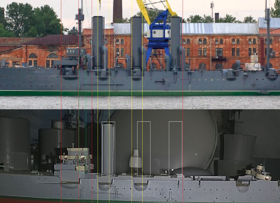
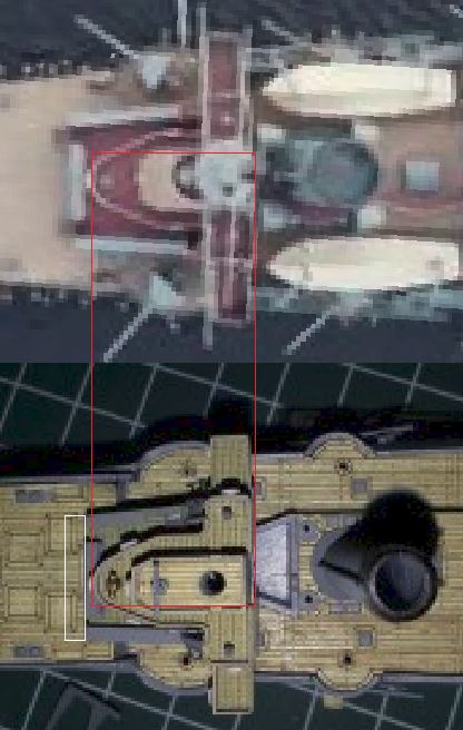
Like repositioning the funnel platforms.

Here are pictures showing the deck pieces separately, for comparison. Nothing has been glued on yet. Is there anything else you can suggest that isn't too complicated?

I was thinking of putting a deck over it, and some added PE detail would be nice to make it look realistic and disguise the abyss, but then it's not the Aurora, if you know what I mean.

This YouTube video (in Russian only): https://www.youtube.com/watch?v=xihQ5-jvdq4 is a build log of the original plastic kit. His deck looks different, because where the bridge ends there is an abyss but no walls around it like my one. But his bridge covers the entire area anyway right up to the funnel. My guess is that the bridge in my kit too small maybe. ARK doesn't seem to care, as in the previous post picture the abyss is clearly there and they haven't bothered to correct it.


Attachments:
IMG_20190101_101829.jpg
IMG_20190101_101829.jpg [ 224.06 KiB | Viewed 3357 times ]
IMG_20190101_101836.jpg
IMG_20190101_101836.jpg [ 318.01 KiB | Viewed 3357 times ]
Top
 Profile  
Reply with quote  
PostPosted: Tue Jan 01, 2019 1:34 pm 
Offline

Joined: Sun Aug 20, 2017 9:46 am
Posts: 1439
Location: Montreal, Canada
If it wasn't for the application of the wooden deck, some scratch-building with sheet, and strip plastic, and re-positioning of the funnels would work. But not so easy now.
:wave_1:


Top
 Profile  
Reply with quote  
PostPosted: Tue Jan 01, 2019 9:56 pm 
Offline

Joined: Wed Mar 09, 2016 5:17 am
Posts: 59
drasticplastic wrote:
If it wasn't for the application of the wooden deck, some scratch-building with sheet, and strip plastic, and re-positioning of the funnels would work. But not so easy now.
:wave_1:


Ok well if it was your model and you were willing to cut your losses with the wooden deck by removing it, what would you do? When I'm back home I will test fit to see how the funnels look if moved forward a cm or two. The rear half of the ship is going to look very sparse.


Top
 Profile  
Reply with quote  
PostPosted: Wed Jan 02, 2019 10:29 am 
Offline

Joined: Sun Aug 20, 2017 9:46 am
Posts: 1439
Location: Montreal, Canada
When a wood deck is applied, they can be difficult to remove because the backing is very sticky. It will require some clean-up to remove adhesive residue and try not to damage the underlying plastic kit. Solvents will certainly be damaging (although Goo-Gone is probably safe). If you buy another replacement wood deck you will have to modify it to fit whatever alterations you make to the kit. If it was my kit and I was determined to correct it, I would probably do the necessary surgery and scratch-work with sheet styrene, and not bother with a wood deck - just paint it. Alternatively, you can buy generic 1/350 laser-etched wood plank sheeting and cut your own sections to fit.
Instead of moving ALL the funnels forward leave the rearmost one where it is and space out the others equally so that the foreward one is where it is supposed to be. That way you won't end up with an awkward blank space somewhere. It may still be not be correct, but it will be better.
:wave_1:


Top
 Profile  
Reply with quote  
PostPosted: Wed Jan 02, 2019 12:23 pm 
Offline
User avatar

Joined: Sat Feb 03, 2007 1:00 pm
Posts: 897
Location: Bowmanville, ON, Canada
Can you post a profile photo of the model?

Like this, https://www.flickr.com/photos/kev_grego ... 487103925/

I may have a simple solution, but need to check something.

Darren

_________________
Darren (Admiral Hawk)
In the not so tropical climate of the Great White North.


Top
 Profile  
Reply with quote  
PostPosted: Wed Jan 02, 2019 6:14 pm 
Offline

Joined: Wed Mar 09, 2016 5:17 am
Posts: 59
Admhawk wrote:
Can you post a profile photo of the model?

Like this, https://www.flickr.com/photos/kev_grego ... 487103925/

I may have a simple solution, but need to check something.

Darren


See attached profile photo.
I placed forward turret, bridge, funnel and rear platforms in their respective fittings to give you an idea.

Thanks drasticplastic, I will see what Darren's proposal is first :wave_1:


Attachments:
IMG_20190103_070054.jpg
IMG_20190103_070054.jpg [ 260.19 KiB | Viewed 3260 times ]
Top
 Profile  
Reply with quote  
PostPosted: Wed Jan 02, 2019 9:33 pm 
Offline
User avatar

Joined: Sat Feb 03, 2007 1:00 pm
Posts: 897
Location: Bowmanville, ON, Canada
First, photos can lie. Perspective is everything and can make things look way different than they are.

Second, Kits always have flaws.

The Photo you provided is good, but it's taken a little too close to make a perfect comparison. However, I think it shows enough to identify the issues.

In this comparison, you see that the kit is off in several spots. To fix the funnel spacing means moving the first 2 funnels forward. However, to do that properly, you need to remake the structure they stand on. That's a lot of work and might be more than you're willing to attempt. Also, if you are going to fix the funnels, then you may as well fix all the other little issues, like the side gun sponson placing.

Image

What I think might be a better solution, is to extend the deck that the bridge structure sits on and move the whole thing back a little. In this photo, the white box shows approx how much you could add to the front. You could move the funnel a small amount forward if you wanted without major surgery. Then, when the vents are put between the bridge and funnel, the gap will be much less noticeable.

Image

I hope that helps a little, whatever you decide to do.

_________________
Darren (Admiral Hawk)
In the not so tropical climate of the Great White North.


Top
 Profile  
Reply with quote  
PostPosted: Fri Jan 04, 2019 3:48 am 
Offline

Joined: Wed Mar 09, 2016 5:17 am
Posts: 59
Thanks for the analysis Darren. I still don't really understand. Do you mean bringing the bridge back like in the pics below? (cutting the long piece on the foredeck and moving that back as well) Have to take care of that wall ending on the main deck, where a stepladder goes on either side.


Attachments:
IMG_20190104_162943.jpg
IMG_20190104_162943.jpg [ 275.34 KiB | Viewed 3219 times ]
IMG_20190104_162835.jpg
IMG_20190104_162835.jpg [ 290.23 KiB | Viewed 3219 times ]
Top
 Profile  
Reply with quote  
PostPosted: Fri Jan 04, 2019 7:40 am 
Offline
User avatar

Joined: Sat Feb 03, 2007 1:00 pm
Posts: 897
Location: Bowmanville, ON, Canada
Close.
leave the main deck the way it is.
Extend the deck above by cutting the block and moving it forward.
You will also have to extend the side blocks and the deck itself to match.
Then the bridge will sit closer to the stack like you have it in the last photo.

Not a perfect solution, but it may save you some work and look reasonably decent.

I can draw you a cutting guide if you'd like.

_________________
Darren (Admiral Hawk)
In the not so tropical climate of the Great White North.


Top
 Profile  
Reply with quote  
PostPosted: Fri Jan 04, 2019 8:58 am 
Offline

Joined: Wed Mar 09, 2016 5:17 am
Posts: 59
Admhawk wrote:
I can draw you a cutting guide if you'd like.


Yes please :thanks:


Top
 Profile  
Reply with quote  
PostPosted: Fri Jan 04, 2019 1:39 pm 
Offline
User avatar

Joined: Sat Feb 03, 2007 1:00 pm
Posts: 897
Location: Bowmanville, ON, Canada
Okay, here you go. Now remember, there are many ways to go about this, I'm just trying to show you what I think might be the simplest.

I tried to give you an overhead view and a perspective view, but the perspective image isn't very good.
Basically, you just cut the front of the bottom level right off at the red line and add a couple of pieces of styrene (plastic) to fill the gap.
The blue is a flat piece of plastic to extend the deck.
The yellow are blocks of plastic to extend the side bulkheads.
You can have the deck piece go all the way across, or just to the yellow blocks, it's totally up to you and where you want the joints to be.
You can see examples A and B in the pic giving a front to back view. I prefer B, either way works.

I like using the small saw blades that fit into an x-acto/Excel knife handle for cuts like this.
Evergreen strips come in all sorts of sizes for this kind of work.
You'll have to do a little filling and sanding to make the joints smooth.
Use Crazy glue and that's about it.

Image

_________________
Darren (Admiral Hawk)
In the not so tropical climate of the Great White North.


Top
 Profile  
Reply with quote  
PostPosted: Fri Jan 04, 2019 9:49 pm 
Offline

Joined: Wed Mar 09, 2016 5:17 am
Posts: 59
Thanks so much Darren. I will give this a shot today.


Top
 Profile  
Reply with quote  
PostPosted: Sat Jan 05, 2019 5:32 am 
Offline

Joined: Wed Mar 09, 2016 5:17 am
Posts: 59
Ok so I've made a good attempt at this but it still looks very rudimentary. I bought grooved styrene which looks close to deck planking, cut a length of that and stuck two pieces of thick styrene on the ends to represent the bulkhead borders. Painted it and this is the end result. Haven't glued it together yet because I don't like it. It doesn't look right because the rest of the deck around it is mesh flooring. Any level of scratchbuilding is really beyond me unfortunately, all I know is how to stick pieces together and paint them.

I could make more attempts, but I can't replicate that mesh decking and without that the scratchbuilt piece will stand out by a mile.


Attachments:
ssss.jpg
ssss.jpg [ 385.54 KiB | Viewed 3172 times ]
ssssss.jpg
ssssss.jpg [ 377.7 KiB | Viewed 3172 times ]
sssssss.jpg
sssssss.jpg [ 166.03 KiB | Viewed 3172 times ]
Top
 Profile  
Reply with quote  
PostPosted: Sat Jan 05, 2019 10:30 am 
Offline

Joined: Sun Aug 20, 2017 9:46 am
Posts: 1439
Location: Montreal, Canada
I think your "mesh" flooring is actually a criss-cross wood planking on the deck. In any case, you put your replacement decking running side to side instead of fore and aft as deck planking should usually run. If you've still got the scrap wood from the decking sheet you can cut out a piece to cover the entire area (original and scratch) and draw on a grid with fine point pen, or pencil, to imitate the plastic grid deck.
:wave_1:


Top
 Profile  
Reply with quote  
PostPosted: Sat Jan 05, 2019 10:48 am 
Offline
User avatar

Joined: Sat Feb 03, 2007 1:00 pm
Posts: 897
Location: Bowmanville, ON, Canada
I think it looks pretty good for a first attempt.

This is where I find scratchbuilding fun, look through your parts stash for a bit of photo etch that looks like the floor grating.
Radars, flight deck netting etc, cut to fit and glue it on top of the new floor piece. But make the floor piece out of plain flat sheet.

A couple of suggestions,
First, Attach a new floor piece to the main section. Make it a little longer side to side, so that the sides stick out. Make sure to align it vertically so that any PE grate you put on will sit flush with existing floor grate.

Image

Now attach what you have found for the floor grate, making sure to align it to the existing grate and that is sits flush with the existing grate.
Next, attach the new side block extensions, ensure they follow the same angle as the existing pieces. leave a bit extra extending fwd over the new deck piece.

Image

Then, sand/cut/file flush across the whole front end. Do the same with the cut edge of the piece you cut off. Sand/trim until the cut piece sits flush with the new extension pieces.

Image

Next, glue the front piece back on to the new extension.
When dry, sand the sides and top smooth and fill any remaining imperfections with putty and sand smooth again.

Image

_________________
Darren (Admiral Hawk)
In the not so tropical climate of the Great White North.


Top
 Profile  
Reply with quote  
PostPosted: Tue Jan 08, 2019 5:00 am 
Offline

Joined: Wed Mar 09, 2016 5:17 am
Posts: 59
I didn't have any reserves of PE materials to overlay the deck to replicate the mesh effect. Tried a few other things, they turned out awful, ended up giving up until revisiting the model today and just sticking some leftover wooden deck over it. Similar to drastic's suggestion but just foregoing trying to replicate the mesh.

My leftover wooden deck is only bits and pieces, since I needed vertical cuts I had to cut out a lot of little squares. Once I sand the edges of the parts down, it should look passable. At least the decking of the top of the wheelhouse is wooden as well, so it doesn't look too out of place. Maybe the wooden strip can be where the sailors wipe their feet before entering into the bridge :big_grin:


Attachments:
IMG_20190108_173439.jpg
IMG_20190108_173439.jpg [ 357.45 KiB | Viewed 3123 times ]
Top
 Profile  
Reply with quote  
PostPosted: Tue Jan 08, 2019 11:08 am 
Offline

Joined: Sun Aug 20, 2017 9:46 am
Posts: 1439
Location: Montreal, Canada
I can't find a better pic than this online:
https://www.industrialmetalsupply.com/P ... y-metals#1
The second item from left is perforated brass sheet. Usually available singly in some model RR shops, along with other shapes and sizes of perforations. I've used it for mesh floors and platforms in larger scales, but the right size perforations will mimic the wood grid pattern on the bridge deck. It's thin brass (similar to the thickness of PE) and easily cut with scissors or small shears.
:wave_1:


Top
 Profile  
Reply with quote  
Display posts from previous:  Sort by  
Post new topic Reply to topic  [ 22 posts ]  Go to page 1, 2  Next

All times are UTC - 6 hours [ DST ]


Who is online

Users browsing this forum: No registered users and 14 guests


You can post new topics in this forum
You can reply to topics in this forum
You cannot edit your posts in this forum
You cannot delete your posts in this forum
You cannot post attachments in this forum

Jump to:  
Powered by phpBB® Forum Software © phpBB Group