The Ship Model Forum

The Ship Modelers Source
It is currently Mon Aug 04, 2025 4:50 am

All times are UTC - 6 hours [ DST ]


Post new topic Reply to topic  [ 355 posts ]  Go to page Previous  1 ... 5, 6, 7, 8, 9, 10, 11 ... 18  Next
Author Message
PostPosted: Sun Mar 13, 2011 1:35 pm 
Offline
User avatar

Joined: Mon Feb 28, 2011 4:45 pm
Posts: 56
Tracy White wrote:
SG-3 wasn't used during the war. YE antenna drawings exist in the AOTS Intrepid book at least and possibly others.


Ah, thanks! I have access to an AOTS Intrepid book and will have a look. I bought some Warship Pictorials on Flanders' Modelling Festival in Antwerp yesterday. No. 31 on the USS Buchanan DD-484 has avery nice view on the back of the SG antenna on page 42 and 45, so that's settled.

On the railings; do you know where the kit lacks them and I have to provide them?


Russ2146 wrote:
Well, here's an SG-3

Attachment:
SG-3 Antenna.jpg


Have you looked at WEM's WW2 USN Radar fret?


Thanks Russ, stupidly enough, I wasn't even aware of a USN radar set from WEM...

Thanks also for the pics on Cowpens. The upper one I had already found, the History101-pic I didn't know about.


Top
 Profile  
Reply with quote  
PostPosted: Sun Mar 13, 2011 2:15 pm 
Offline

Joined: Tue Nov 03, 2009 9:28 pm
Posts: 2126
Location: Egg Harbor Twp, NJ
Attachment:
CVL 25 Island (3).jpg
CVL 25 Island (3).jpg [ 78.46 KiB | Viewed 3663 times ]


Top
 Profile  
Reply with quote  
PostPosted: Sun Mar 13, 2011 3:58 pm 
Offline
User avatar

Joined: Mon Feb 27, 2006 10:32 pm
Posts: 294
Location: South Carolina
Hey guys. I have the Dragon 1/350 USS Independence kit. I plan to build USS Belleau Wood, late 1944 before modification. What differences were there between the two ships? Thanks for your thoughts.
Walt Haynes


Top
 Profile  
Reply with quote  
PostPosted: Mon Mar 28, 2011 1:05 am 
Offline

Joined: Wed Mar 28, 2007 10:06 pm
Posts: 33
Wayne,
Im doing the Indy right now, but you might take a look at the link below. A site dedicated to all 9 of the CVLs

http://www.ninesisters.com/cabot.htm


Top
 Profile  
Reply with quote  
PostPosted: Mon Mar 28, 2011 1:26 am 
Offline

Joined: Wed Mar 28, 2007 10:06 pm
Posts: 33
Wayne,
I did some checking myself, and it looks like your up against the same thing I am if you want to do the Wood after her 1944 refit. She had a second cat added like the Indy, as well as relocation of the the 20mm's, etc. You'll have to scratchbuild the bow blisters that housed the addl. cat machinery. Not too difficult, I did it with some .010" styrene sheet. Had to work out the shapes using the drawings from here http://www.hnsa.org/doc/plans/cvl26.pdf. Fabulous drawings btw. If you need any tips, let me know. Its easier than I thought it would be. I have a few pics of mine in progress. If you would like to see them contact me. I havent been able to figure out how to post pics here.

Joe


Top
 Profile  
Reply with quote  
PostPosted: Mon Mar 28, 2011 1:28 am 
Offline
User avatar

Joined: Mon Jan 10, 2005 6:00 pm
Posts: 12338
Location: Ottawa, Canada
Hey Joe, if you're looking for instructions on posting photos, this thread may be of aid, if you have not seen it yet: viewtopic.php?f=12&t=1261

_________________
De quoi s'agit-il?


Top
 Profile  
Reply with quote  
PostPosted: Mon Mar 28, 2011 1:52 am 
Offline

Joined: Wed Mar 28, 2007 10:06 pm
Posts: 33
Tim,
Thanks for the input. Ill try it right now and see if it works.

Joe


Attachments:
DSC05209.JPG
DSC05209.JPG [ 114.1 KiB | Viewed 3566 times ]
DSC05208.JPG
DSC05208.JPG [ 114.81 KiB | Viewed 3566 times ]
DSC05207.JPG
DSC05207.JPG [ 122 KiB | Viewed 3566 times ]
Top
 Profile  
Reply with quote  
PostPosted: Mon Mar 28, 2011 1:54 am 
Offline
User avatar

Joined: Mon Jan 10, 2005 6:00 pm
Posts: 12338
Location: Ottawa, Canada
Yep! Works great :)

_________________
De quoi s'agit-il?


Top
 Profile  
Reply with quote  
PostPosted: Mon Mar 28, 2011 1:55 am 
Offline

Joined: Wed Mar 28, 2007 10:06 pm
Posts: 33
Wheee, it works! Thanks again Tim.


Top
 Profile  
Reply with quote  
PostPosted: Mon Mar 28, 2011 1:59 am 
Offline

Joined: Wed Mar 28, 2007 10:06 pm
Posts: 33
Gonna be a while before I have any more. Im in the middle of packing for a move from Socal to Portland Or. so shes back in the box for now. Hopefully there will be a PE set available for her by the time I get settled up there. In the meantime, I'll be looking forward to seeing other builds of this great kit here. Wayne, again Ill be glad to help any way I can. Let me know.

Joe


Top
 Profile  
Reply with quote  
PostPosted: Fri May 13, 2011 8:27 am 
Offline
User avatar

Joined: Sat Sep 30, 2006 9:30 pm
Posts: 363
Location: Richmond TX
Question for Tracy - I'm looking at photos of Independence after refit and repaint into camo. Regarding the bow guns, if I were to model CVL-22 at this point, would I be correct in assuming I have to remove the gun tubs on part G4 altogether? I'm looking at the bottom photo on page 14 of the Squadron book and it looks like they are completely gone. It's just hard to tell from the angle. If they are gone, I am guessing the structures G9 and G7 are also removed and it is just a platform connecting the gun director to the main bulkhead. Thanks in advance for your help.


Top
 Profile  
Reply with quote  
PostPosted: Fri May 13, 2011 10:21 am 
Offline

Joined: Mon Jan 10, 2005 11:02 am
Posts: 10572
Location: EG48
Yes, I believe you would be better served just modifying G1 and scratch-building a new platform aft of it... you can see how this area was constructed in the USS Monterey CVL-26 plans posted on the Historic Navy Ships Association Booklet of General Plans page (Sheet 9). The two small rooms you mentioned (G7 & G9) were 20mm clipping rooms, which were replaced by a 40mm clipping room... actually, it's possible that G9 was a 20/40mm clipping room or that one was used for 20s and the other for 40s when the 5" was swapped out; the plans we were working from for CVL-22 were a combination of a couple of ships and the shapes of the things I pulled from, I think, a sheet diagramming metal thickness that didn't label precisely what the internals were used for at the time.

Sorry, rambled there for a bit....

_________________
Tracy White -Researcher@Large

"Let the evidence guide the research. Do not have a preconceived agenda which will only distort the result."
-Barbara Tuchman


Top
 Profile  
Reply with quote  
PostPosted: Sun May 15, 2011 9:35 am 
Offline
User avatar

Joined: Sat Sep 30, 2006 9:30 pm
Posts: 363
Location: Richmond TX
Thanks Tracy - I had seen those plans but wasn't 100% on using them. I have printed out the relevant sections and I will scratch a new forward section. I will post pics when I have got it.


Top
 Profile  
Reply with quote  
PostPosted: Mon Jun 06, 2011 10:18 am 
Offline
User avatar

Joined: Tue Jan 11, 2005 1:40 pm
Posts: 8360
Location: New Jersey
Nice build up review of the Dragon 1/350 CVL-22 posted over on the IPMS/USA website by Bill Kluge

_________________
Martin

"Tomorrow is the most important thing in life. Comes into us at midnight very clean. It's perfect when it arrives and it puts itself in our hands. It hopes we've learned something from yesterday." John Wayne

Ship Model Gallery


Top
 Profile  
Reply with quote  
PostPosted: Thu Jun 23, 2011 11:55 am 
Offline

Joined: Mon Jun 13, 2011 9:41 am
Posts: 4
Hi

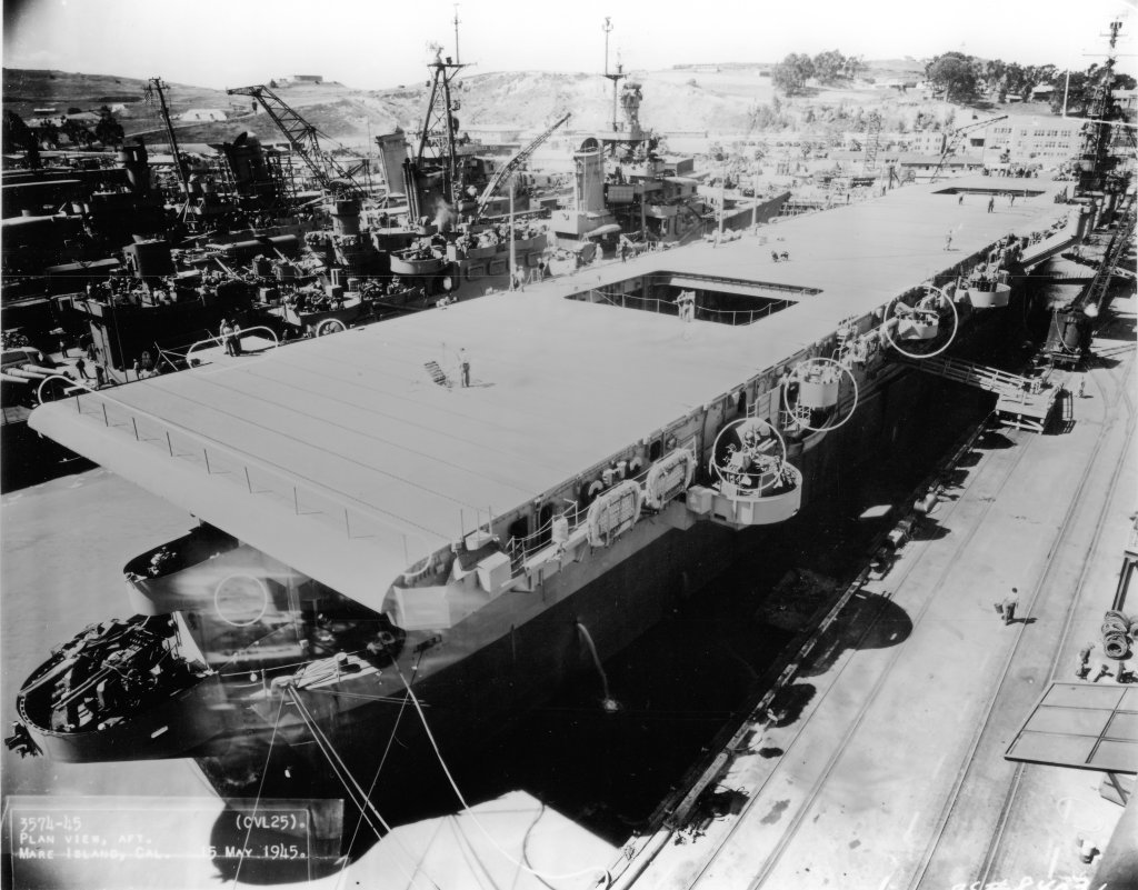
My name is Antonio Almeida, and I am a new member here. My main modelling area is ground-related, but I am trying to build a 1/700 CVL. I have the Revell boxing which, supposedly, depicts the Independence. My preference, however, goes to a measure 33, design 7A camouflaged ship, namely either the San Jacinto or the Cowpens. Because I am a landlubber, my printed references are quite short. I have several doubts concerning some details. Any help will be greatly appreciated.

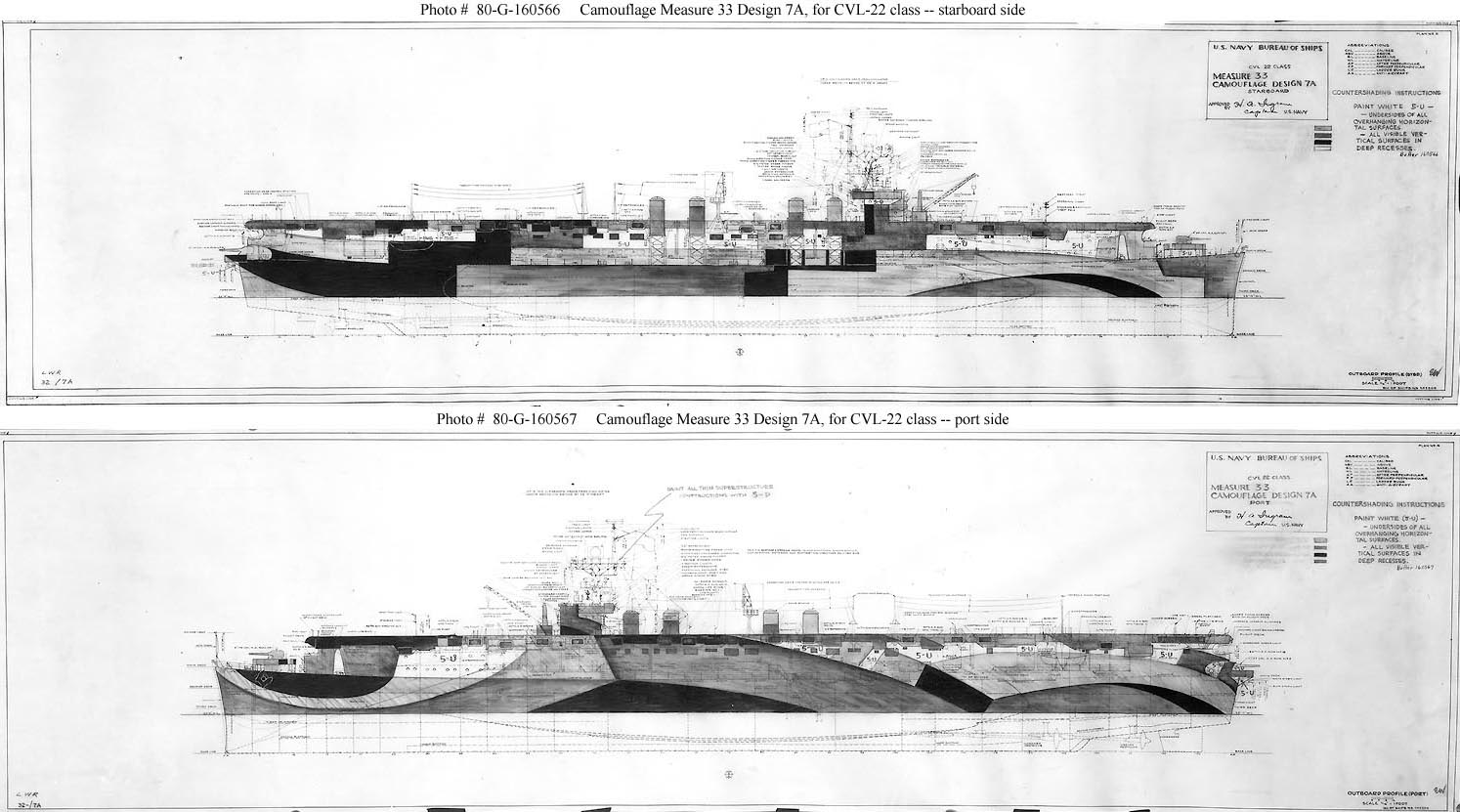
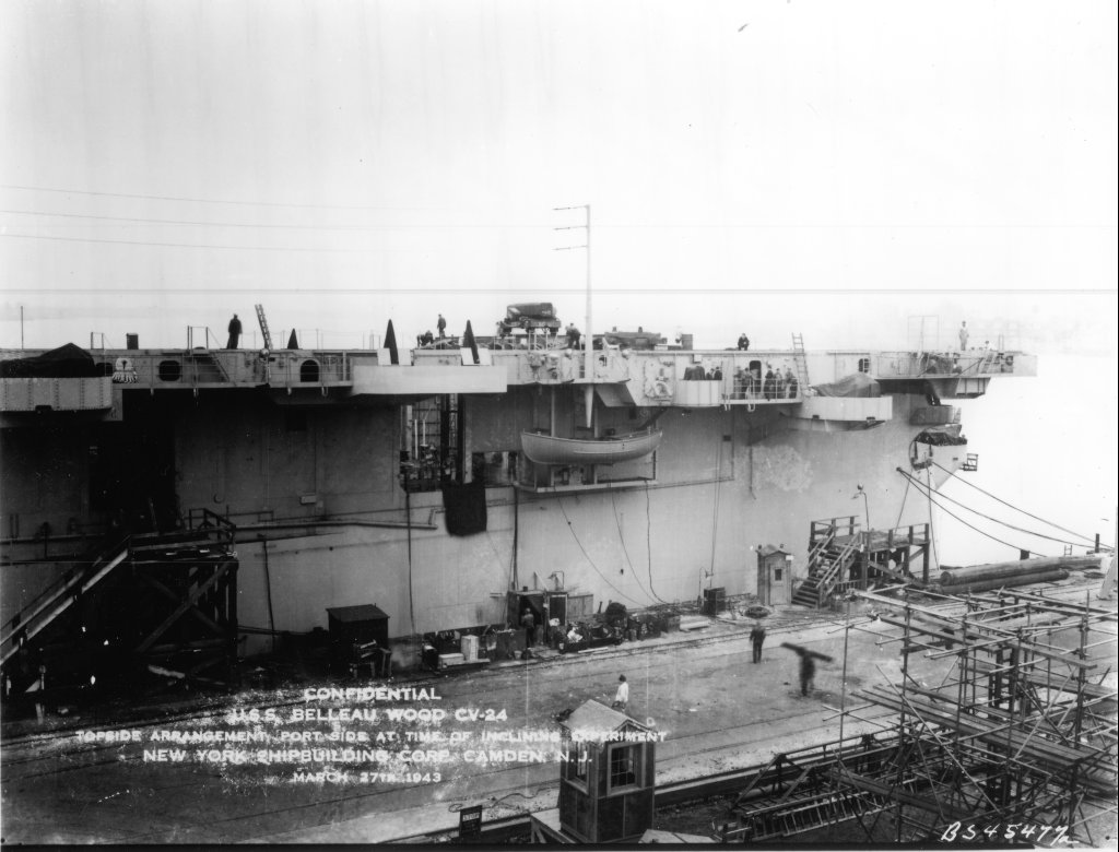
I haven´t been able to find the camouflage patterns for the sides of the chimney stacks, as the usual culprit misses this point in this measure:
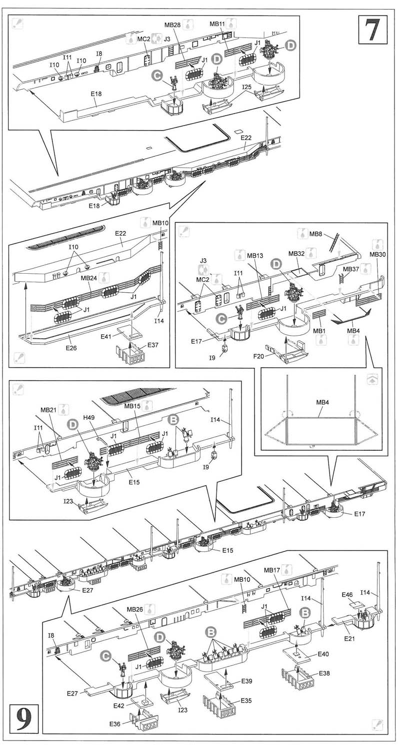
http://www.shipcamouflage.com/DesignShe ... CVL-22.jpg

What is the exact number of the 20mm gun mounts? I have consistently read 16 mounts, but the instructions show 19: 2 mounts on the bow, 2 on the stern, 10 to port, five to starboard. (The sequence of tubs, from bow to stern – port, 13 tubs: 3x20mm, fire director, 40mm, 40mm, fire director, 40mm, 4x20mm, 1x20mm, fire director, 40mm, 2x20mm, fire director, 40mm; starboard, 10 tubs: fire director, 40mm, 40mm, 2x20mm, 1x20mm, fire director, 40mm, 2x20mm, fire director, 40mm)

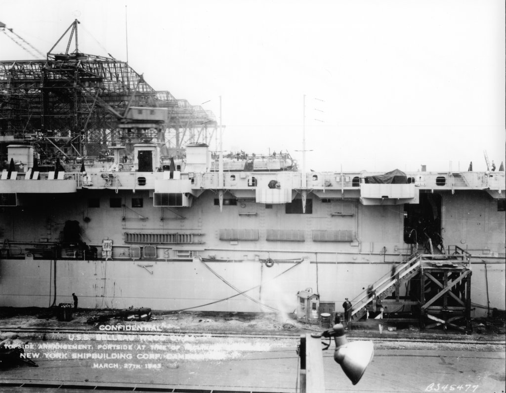
Under some port-side tubs the photos show a kind of box or stack. They are missing from the kit, what´s their function and location? Are they some kind of support for the radio masts?
Also missing are the four(?) radio masts, port side also. Once again, what´s their exact location?

How where the life-boats suspended? Once again, kit and instructions are misteriously vague on this. Is there a clear photo of this area?

Where can I find the number and location of the acces doors to the catwalks?

Do the 40mm quad mounts on the bow and stern always carried their frontal shields? I would like to depict a ship without them, how usual/unusual was that?

Would a ship anchored at Ulithy have its 20mm guns covered with canvas, or would they be ready for action?

Finally, I have a trade on trading post, including PE sets. Please check it

Thanks, Antonio


Top
 Profile  
Reply with quote  
PostPosted: Thu Jun 23, 2011 11:37 pm 
Offline

Joined: Mon Jan 10, 2005 11:02 am
Posts: 10572
Location: EG48
You have many questions. I have not seen the Revell kit and cannot find photos of it built up or still on parts trees online. I will answer what I can.

CV-25 in MS 33 / 7a:
2 x 20mm on stern above quad 40mm
4 x 20mm port and starboard (two each side) outboard of rear elevator
4 x 20mm port side, opposite of #3 stack
2 x 20mm starboard side in between #2 and #3 stacks
6 x 20mm port & starboard (three each side) just ahead of the forward catwalk Mk 51 director tub.
2 x 20mm just underneath forward edge of flight deck, behind bow quad 40mm.
Total = 20

CVL-30 San Jacinto in MS 33 / 7a:
Same as CVL-25, except that the two 20mms between the exhaust stacks were further outboard, so that the airplane parking platform was continuous. Quickest photo I can find online is this one of CVL-23 Princeton which had the same arrangement.

With regards to the port side boxes, I think you are talking about the air intakes. Are there four of them? Do they look like parts E35 - E-38 on this page of Dragon's 1/350th instructions? This photo of CVL-24 Belleau Wood?

Antenna location can be seen on the same page of instructions on the bottom drawing.

Live boats were suspected by pulleys hanging under catwalks above bow and stern of boats. Part of the structure holding the platform underneath the boats also had a support that the boat rested on, more as a sway brace. See this photo of CVL-24 Belleau Wood

Only source online I can give you for the catwalk doors are for CVL-26 Monterey here:
http://www.hnsa.org/doc/plans/index.htm
There are some differences, but it should give you a good start.

I can find no photos of Quad 40mms with splinter shields in place.

Covers on guns were mainly for bad weather; you do not see them often at Ulithi.

_________________
Tracy White -Researcher@Large

"Let the evidence guide the research. Do not have a preconceived agenda which will only distort the result."
-Barbara Tuchman


Top
 Profile  
Reply with quote  
PostPosted: Fri Jun 24, 2011 11:20 am 
Offline

Joined: Mon Jun 13, 2011 9:41 am
Posts: 4
Hi Tracy

Thank you very much for your reply. It is very, very, helpful. Still have a couple of doubts, though.
Revell’s kit is, AFAIK, a reboxing of the original Dragon moulds, without PE and the extra parts.

The 20mm guns. I had missed the three on starboard, near the bow. Squadron book, page 18, bottom photo, shows them, stupid me. But I still have doubts concerning the tub with a single mount, both on port and starboard, above the fourth air intake (port), just behind the chimneys (starboard). Squadron book, same page, top photo clearly shows that mount, just in front of one of the radio masts. That makes 21! But what about starboard?

(Also, I had missed that the parking platform near the chimneys was continuous.)

The four boxes on port side. Air intakes. Dragon’s instructions show them rectangular in profile, but in large detail photos in Model ship guide, vol 1, edited by pit road, show that they were somewhat triangular in shape near the opening. Squadron book, page 13, bottom photo also shows that, I think.

And still the colours in the chimney’ sides remain elusive…
Once again, thanks for your help

Antonio


Top
 Profile  
Reply with quote  
PostPosted: Sat Jun 25, 2011 10:24 am 
Offline

Joined: Mon Jan 10, 2005 11:02 am
Posts: 10572
Location: EG48
Antonio Almeida wrote:
Squadron book, same page, top photo clearly shows that mount, just in front of one of the radio masts. That makes 21! But what about starboard?


I did some more looking after reading this; you can add these two port and starboard to the total above for at least part of their service. I have found photos of them on both CVL-25 and -30 "as launched." Unfortunately I do not have a lot of good photos of CVL-25 in dazzle and none of CVL-30 in the Pacific. I can see that CVL-25 in her 1945 overhaul photos had no 20mm just aft of the stack, and the area is not circled as if it was work done at that time (I have a better copy of this photo). So it is hard to know when the work was done and if this gun was present when she was in dazzle or just part of the time when she was in dazzle.

_________________
Tracy White -Researcher@Large

"Let the evidence guide the research. Do not have a preconceived agenda which will only distort the result."
-Barbara Tuchman


Top
 Profile  
Reply with quote  
PostPosted: Sat Jun 25, 2011 8:15 pm 
Offline

Joined: Mon Jun 13, 2011 9:41 am
Posts: 4
Hi Tracy

22 it will be. If later photos prove me wrong, Murphy's law always ready, well, who's counting? :cool_2: :big_grin:

Hope to post some pictures soon. Thanks again

Antonio


Top
 Profile  
Reply with quote  
PostPosted: Mon Jul 11, 2011 4:05 pm 
Offline

Joined: Wed Mar 28, 2007 10:06 pm
Posts: 33
Question for Tracy,

In the kit, the starboard flight deck extensions, parts E-4 and E-8, are flat solid plastic. I was just looking at the new WEM PE set and it appears they have replacement parts for these parts. The photo isnt clear, but it appears these parts were grating and not solid metal. Is that correct?


Top
 Profile  
Reply with quote  
Display posts from previous:  Sort by  
Post new topic Reply to topic  [ 355 posts ]  Go to page Previous  1 ... 5, 6, 7, 8, 9, 10, 11 ... 18  Next

All times are UTC - 6 hours [ DST ]


Who is online

Users browsing this forum: No registered users and 64 guests


You can post new topics in this forum
You can reply to topics in this forum
You cannot edit your posts in this forum
You cannot delete your posts in this forum
You cannot post attachments in this forum

Jump to:  
Powered by phpBB® Forum Software © phpBB Group