The Ship Model Forum

The Ship Modelers Source
It is currently Tue Apr 16, 2024 6:17 pm

All times are UTC - 6 hours [ DST ]


Post new topic Reply to topic  [ 979 posts ]  Go to page Previous  1 ... 43, 44, 45, 46, 47, 48, 49  Next
Author Message
PostPosted: Sat Sep 24, 2022 9:07 pm 
Offline
User avatar

Joined: Tue Jan 11, 2005 1:40 pm
Posts: 8174
Location: New Jersey
admiralcag wrote:
Thank you, sir!

MartinJQuinn wrote:
Don't think I did a WIP thread with her


I could have sworn I picked up using the Five Star portholes from you. Hmmm...

Vern


No sir. Here are two current CV-6 WIP threads:

viewtopic.php?f=59&t=351463

viewtopic.php?f=59&t=164595

I think the 2nd one is the one using the portholes.

_________________
Martin

"Tomorrow is the most important thing in life. Comes into us at midnight very clean. It's perfect when it arrives and it puts itself in our hands. It hopes we've learned something from yesterday." John Wayne

Ship Model Gallery


Top
 Profile  
Reply with quote  
PostPosted: Sat Oct 01, 2022 9:11 am 
Offline

Joined: Tue May 01, 2007 5:35 am
Posts: 10
Again, my thanks!

Vern


Top
 Profile  
Reply with quote  
PostPosted: Tue Nov 01, 2022 12:22 pm 
Offline

Joined: Fri Oct 07, 2022 9:37 am
Posts: 14
Hi everybody, name's Hugo, I discover your thread during my search for infos for my 1/200 Enterprise build, and what a thread !

But now, I have some questions about the CV-6 for late 1942, the Trumpeter kit appearance of the carrier :
First: what was the fire director for the Chicago Piano 1.1 inch in the guntube on the forecastle on the bow. A Mk51 like the 40mm quad have ?
Image
Second: for how long the 2 50.cal remained on the extremity of the flight deck above the forecastle ?
Image
Third: the bottom of the 5 inch guns seems to lack the "skirt" or splinter shield on that photo form early 1942, on other photos of 5 inch gun we can see that protection at the base of the gun. By late 1942 what was the appearance of the 5 inch ?
Image
Image
Four: It seems that the antennas of the fire directors and the CXAM are painted in a lighter color than the 5-N Navy blue of the vertical surfaces of the ship, especially on the last one :
Image
Image
Image
Or is that just the sun reflection ?

Five : anybody knows if she was carrying whale boats and admiral boats by late 1942 ? Trumpeter gives a lot of boats but mainly for the pre-war appearanc of the ship.

So thats it for now, I will post ome photos of my build and sorry for my bad spelling I am french !

Hugo


Top
 Profile  
Reply with quote  
PostPosted: Sat Nov 12, 2022 7:48 pm 
Offline
User avatar

Joined: Fri Jun 02, 2006 6:36 pm
Posts: 72
Abram,

Don't know if this will answer all your questions, but it sure couldn't hurt!

http://www.modelwarships.com/reviews/books-plans/warship-pictorial/wp-50_EnterpriseCV6Pt1/Book%20Review_TheBigEpt1.htm

Michael


Top
 Profile  
Reply with quote  
PostPosted: Sun Nov 13, 2022 1:53 am 
Offline

Joined: Thu May 29, 2008 8:02 pm
Posts: 3825
Note; Antennas were NOT PAINTED. Paint would impact electronic performance. A varnish was applied. The initial varnish was glossy (causing reflections) and determined to not be dark enough. So, eventually a flat varnish with a darker tone was used on antennas. I have not found any documentation stating so, but I'm pretty sure this varnish wasn't provided to ship's crew for application on existing installed antennas. Most radars, including antennas, were being replaced with newer equipment as the war progressed, and as such the older antennas were simply removed and maybe refurbished for use elsewhere or just scrapped.


Top
 Profile  
Reply with quote  
PostPosted: Mon Nov 14, 2022 11:22 am 
Offline
User avatar

Joined: Tue Mar 27, 2007 12:34 pm
Posts: 518
Location: Smithfield, Virginia
Regarding the two pictures of the two 5"/38 open mounts, here's the gouge.
YORKTOWN and ENTERPRISE were completed with 5"/38 Mk. 21 open single mounts as shown in the top photo of the two, without the shields on the front of the gun platform.
HORNET (CV-8) was completed with Mk.24 mounts like those in the lower picture (I believe shown here on HORNET (CV-12). All the ESSEXs (CV-9 and up) were completed with Mk. 24s from what I have found. CV-8 Got the newer mounts because she was built later than her "sisters" as a "repeat YORKTOWN" and also had some other changes made at the time of her construction and fitting out. (This latter situation a constant irritation and source of soul-searching for those of us looking to build an accurate CV-8 model from existing YKTN kits for less than the GDP of most developed nations.)
I found a reference stating that ENTERPRISE was backfitted with the Mk. 24 mounts at Pugent Sound in 1943. Perhaps this was coincident with other changes to ENT such as hull blistering.

_________________
Some people make you happy, then they leave.
Others make you happy when they leave. (apologies to Oscar Wilde if he ever said anything similar, of which there is some doubt . . .)


Top
 Profile  
Reply with quote  
PostPosted: Tue Nov 15, 2022 12:23 pm 
Offline
User avatar

Joined: Fri Jun 02, 2006 6:36 pm
Posts: 72
Rick E Davis wrote:
Note; Antennas were NOT PAINTED. Paint would impact electronic performance. A varnish was applied. The initial varnish was glossy (causing reflections) and determined to not be dark enough. So, eventually a flat varnish with a darker tone was used on antennas. I have not found any documentation stating so, but I'm pretty sure this varnish wasn't provided to ship's crew for application on existing installed antennas. Most radars, including antennas, were being replaced with newer equipment as the war progressed, and as such the older antennas were simply removed and maybe refurbished for use elsewhere or just scrapped.


This is interesting, Rick. I never knew this, but it certainly makes sense. So radar, etc. antennae on (say) the Enterprise in mid-'42 would be a glossy metallic steel color?

Michael


Top
 Profile  
Reply with quote  
PostPosted: Tue Nov 15, 2022 2:50 pm 
Offline

Joined: Thu May 29, 2008 8:02 pm
Posts: 3825
The antennas weren't a "silver" color as such. The varnish was applied over the metal "reflector" part of the antenna to protect from corrosion. The metal was in and of its self not "bright", but the varnish was glossy and reflected sunlight making the antenna appear bright. The Mk 4 (FD) and early SG antennas were much more noticeable than the air search antennas (SC-1 and SA). That was due to the more reflective surface seen by the Mk 4 and SG antennas even though they were smaller than the air search radars with more open mesh. The Mk 4 and SG antennas were parabola and would reflect light in a beam (matching the radar's radar beam).

So think of the varnish you get for use in your house or on furniture, and realize the difference between GLOSS and MATTE varnish.

Attached is an example of a strong sun reflection off these antennas and compared to the 5-N paint of the ship. Other photos taken of the same ships, but the sun is backlit or off angle won't show nearly as bright. In this photo, the Mk 4 antennas show very bright even at the furthest distance, while the SC-1 antennas off angle don't. Even the SA antenna on USS TAYLOR furtherest from the camera, which is looking directly at the camera doesn't show as reflective.

Image

I don't have many images of USS ENTERPRISE showing her antennas in mid-1942. But, this photo dating from November 1942, seems to show the reflection issue, particularly with the FD antenna.

Image


Top
 Profile  
Reply with quote  
PostPosted: Fri Nov 18, 2022 9:20 am 
Offline

Joined: Fri Oct 07, 2022 9:37 am
Posts: 14
Thanks for all the replies ! So I was not crazy the antennas were in a different color. And I think on the last photo of CV-6 at Nouméa, I can see the 50. cal on the front of the flight deck. I guess I have my answer too for the 5inch Gun. Still what about the directors of the 1.1 inch and 40mm in 1942 ?

An other one : when the front boat crane near the island was removed ? At the same time that the flag ship was removed, so before the Santa Cruz battle ? I believe it is not shown on the Noumea photos.

Image

Thanks you all !


Top
 Profile  
Reply with quote  
PostPosted: Fri Nov 18, 2022 5:19 pm 
Offline
User avatar

Joined: Mon Aug 06, 2007 6:29 pm
Posts: 1952
The forward searchlight on each side of the stack was removed in March or April of '42. The platforms for the lights were not reduced in size until the repairs after the Eastern Solomons battle. The boat crane you have circled was removed after Midway and before Eastern Solomons. The Flag Bridge level was removed during the post Eastern Solomons repair. A MK-4 radar was installed on the forward MK-33 director after Midway, before Eastern Solomons. One was installed on the after MK-33 during the post Eastern Solomons repairs.


Top
 Profile  
Reply with quote  
PostPosted: Sat Nov 19, 2022 3:46 pm 
Offline

Joined: Fri Oct 07, 2022 9:37 am
Posts: 14
Alright, so Trumpeter was right to not provide a front crane. But what was that little crane that was replacing it ? She appeared too before the Eastern Solomon ?

https://zupimages.net/viewer.php?id=22/46/ao36.jpg


Top
 Profile  
Reply with quote  
PostPosted: Sat Nov 19, 2022 8:59 pm 
Offline
User avatar

Joined: Mon Aug 06, 2007 6:29 pm
Posts: 1952
The original crane was for handling the ship's boats that were stowed outboard of the island. The small boom crane that was added was probably for handling light cargo. It appears to have been there at Eastern Solomons, but I can not verify that beyond doubt. It remained in place after her big refit in late 1943.


Top
 Profile  
Reply with quote  
PostPosted: Sat Nov 19, 2022 11:56 pm 
Offline

Joined: Fri Oct 07, 2022 9:37 am
Posts: 14
Thanks for your replies ! For the Mk33 director, were they enclosed and if yes, when ? Because on the Noumea photos, they look like Mk37 (but I know they put Mk37 only during the Puget Sound refit).

Image

A picture of my CV-6 in construction :
https://zupimages.net/viewer.php?id=22/46/433a.jpg

And how the Mk33 are shown in the Trumpeter kit, are they good for late 1942 ? :
https://zupimages.net/viewer.php?id=22/46/l504.jpg


Top
 Profile  
Reply with quote  
PostPosted: Sun Nov 20, 2022 12:53 am 
Offline
User avatar

Joined: Mon Aug 06, 2007 6:29 pm
Posts: 1952
The directors were the open topped MK-33's until her late 1943 refit. However, all open topped MK-33 (and MK-28) directors could be closed over with a canvas weather cover. That is what you are seeing in the photo.


Top
 Profile  
Reply with quote  
PostPosted: Mon Nov 21, 2022 9:06 am 
Offline

Joined: Fri Oct 07, 2022 9:37 am
Posts: 14
Thanks Dick. About the portholes issue, I read somewhere on this topic that all the portholes below the hangar level were plated over after Midway and the loss of CV-5. Is that was applying too to the portholes just below the degaussing cables ?

https://zupimages.net/up/22/47/e4f3.jpg (ignore the 50.cal encircled)


Top
 Profile  
Reply with quote  
PostPosted: Fri Nov 25, 2022 1:23 pm 
Offline
User avatar

Joined: Fri Jun 02, 2006 6:36 pm
Posts: 72
I've finally pulled the trigger and ordered the Merit/I Love Kit Big E for my Hannukah gifty. :woo_hoo: As I've probably mentioned before (ad nauseum), I want to build it in Midway configuration and I understand (thank you, Martin) that the kit depicts her as she appeared at Santa Cruz, with the exception of having TBDs instead of TBFs. So, I've spent some time comparing pictures of the kit parts and instructions sheets of the Yorktown and Enterprise kits online, as well as info from various online sources and my own referfences to come up with a list of changes I need to make. Happily, most (not all) of the parts from the Yorktown remain in the Big E kit, which makes things easier. Here's what I have so far (the steps refer to the Enterprise instructions.) Please feel free to comment if I have things wrong!

Step 1: drill out the open hatches in port and stbd quarters

Step 5: make 32 x 20mm guns, 4 x 1.1 inch quads (step 18), no 40mm. Unfortunatly, while the kit has enough 20mm guns, it does not have enough
photoetch gun shields. Happily, I have a GMM Hornet set to make up the deficiency.

Step 6: use part A7 instead of T5 & N9. Add two 20mm guns. This is the raised gun mount on the forecastle.

Step 9: use E3 and L52 on stbd quarter instead of E3 and T4. Do not trim E3. Use E2 and C1 on port quarter instead of E2 and T3. Do not trim E2.
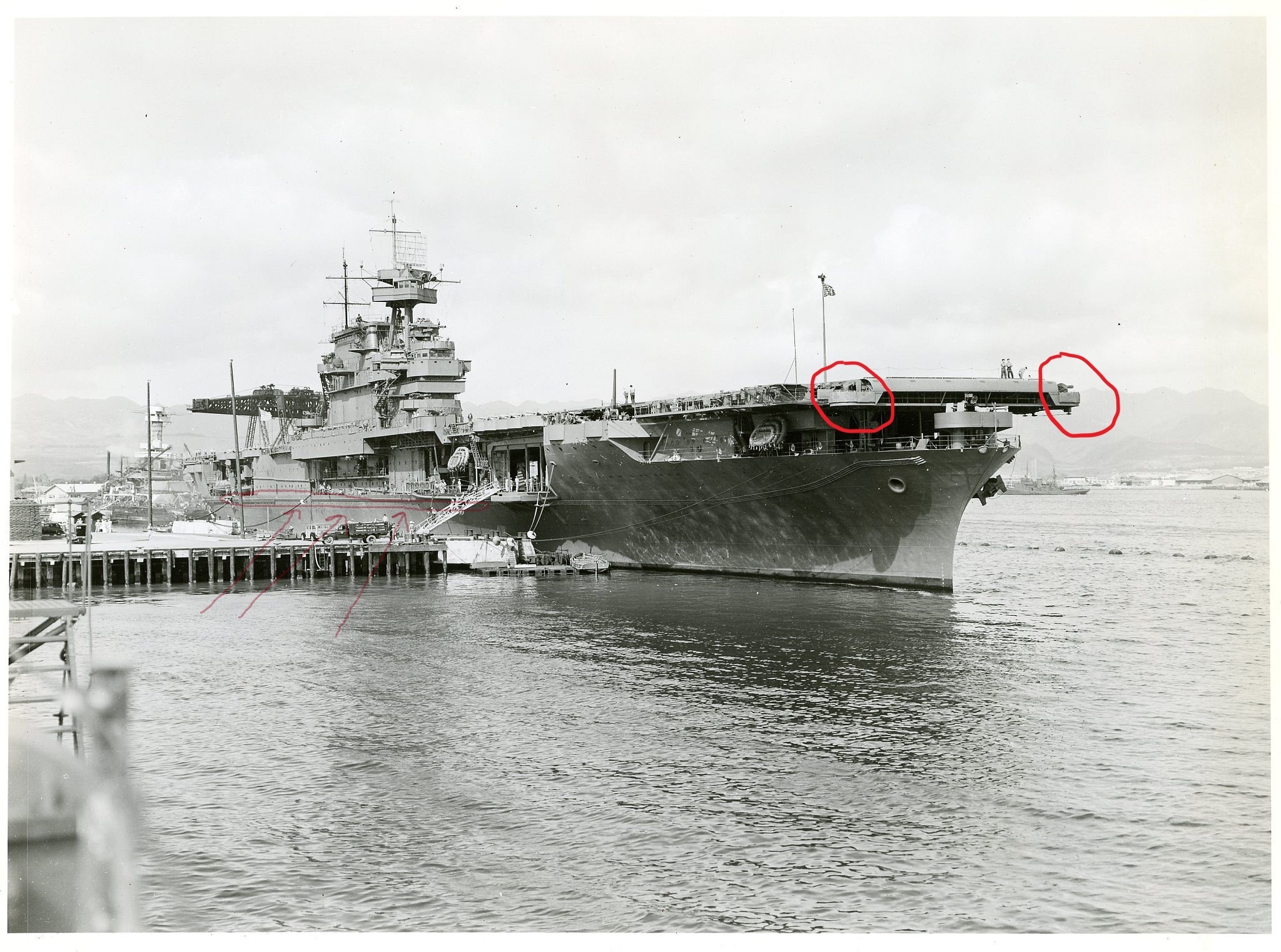
PE-B27 instead of PE-E44. This substitutes two .50 cals instead of the four on the aft corners of the flight deck installed after Midway.

Step 10: cut 40mm tub off of S3 and director tub off of S10, fare them together. This is the trickiest part for me but I think I have it correct.

Step 16: DO NOT cut round down. Leave room for forward boat crane (see steps 26-27). This was removed after Midway but still there during that
battle. Again, GMM Hornet set to the rescue. DO NOT remove raised part of forward flight deck part W1 (the location for the 1.1 inch gun
mount.) DO NOT open hole just ahead of island for the 40mm quad gun mount. Open hole outboard of forward edge of midship elevator.

Step 18: do not make 40mm guns, tubs, directors. Make 4 x 1.1 in quads, parts P17, 18, and 19, tubs, and gun mounts, etc.

Step 20: Use only two .50 caliber guns P28 on aft corners of flight deck (one each side, see step 9). DO NOT add 40mm quad to stbd side aft gallery
or part N9. Use railings to clean area up where tubs were removed in step 10.

Step 21: DO NOT install Mk.4 radars (PE-E34, 35, 37, 38 & 39) on gun directors

Steps 26-27: Make forward boat crane from GMM Hornet set, add ahead of gun gallery outboard of island.

And here are the colors I believe are correct for Midway from the various sources I've studied:

All vertical surfaces: 5-S Sea Blue (I know, still controversial, but I think based on the evidence the most likely color)

Flight deck: Norfolk 250-N stain. No elevator surrounds; yellow dashes, straight lines, center line only extending to just aft of midship elevator. I have
the Starfighter decals for this.

All external steel decks: 20-B Deck Blue (as well as metal areas on flight deck such as tie downs, surrounds of elevators and deck? This would mean
a lot of maskng, but would make a nice subtle contrast)

Hangar deck: #20 Standard Deck Gray

Hangar bay bulkheads & overheads: white

Radar antennae: metallic (steel?) with a glossy varnish

Sorry for the huge post, but this forum seems to have the best answers that I've found anywhere, and I really appreciate everyone's feedback! I'd like to get this as correct as possible, so I figured this was the place to go. Thanks again for all the info over the years and any help you can give me now that I'm about to take the plunge! :thumbs_up_1:

Michael


Top
 Profile  
Reply with quote  
PostPosted: Sat Dec 03, 2022 1:07 pm 
Offline

Joined: Sun Feb 27, 2011 1:22 pm
Posts: 4
There has been some good pictures and info about the Enterprise lately. I have the
1/350 and 1/200 CV-6 to build. Wish Trumpeter would put out some 1/200 Avengers
and Hellcats to go with the SBD's and Wildcats.

Cheers...Ron


Top
 Profile  
Reply with quote  
PostPosted: Mon Dec 19, 2022 10:28 am 
Offline
User avatar

Joined: Fri Jun 02, 2006 6:36 pm
Posts: 72
Some more questions about backdating the Merit/I Love Kit Enterprise.

The various sources I have seem to agree that at the time of Midway, Enterprise had 32 single 20mm gun mounts. Based on the kit instructions compared to photos and the Yorktown instructions, I come up with the following for placements of these guns:

Step 6: x2 in bow tub (instead of the quad 1.1)
Step 20: x24 (along flight deck galleries. They look like .50s in instructions) (poss x22 depending whether there were any in the quarter galleries)
Step 26: x3 (they look like .50s in instructions)?
Step 27: x8 (they look like .50s in instructions) (poss less based on boat crane)

My questions are:

The two shown in the quarter galleries forward of the .50s. Were they there at the time, or added later?

The three shown in step 26 are on the island, 2 forward of the funnel on port and starboard sides and one aft of the funnel to starboard. I cannot be sure if any or all of these were there at Midway. Any thoughts?

The eight in step 27 are the ones outboard of the island along the starboard edge of the deck where the boats used to be. The kit doesn't have a crane there but I know it was still in place forward of these guns at Midway. Would there have been eight 20mm's there when the crane was still there, or less?

I'm trying to get this as close to correct as possible with my limited knowledge/skill. Thanks for any help!

Michael


Top
 Profile  
Reply with quote  
PostPosted: Mon Dec 19, 2022 12:34 pm 
Offline
User avatar

Joined: Mon Aug 06, 2007 6:29 pm
Posts: 1952
As near as I can make out from the photos, she had 32 20MM and 8 .50's. The 20MM were as follows: 2 in the bow bandstand, 5 each in the catwalks port and starboard just aft of the forward 5" gun galleries, 5 in the port catwalk just aft of #2 elevator, 3 to starboard in the same location, 2 in the starboard catwalk bracketing the top of the hangar level boat crane, 2 on the stern at hangar deck level (those were intended to be cut into the aft flightdeck round down, but that wasn't done until after Midway) and 8 outboard of the island. All had steel splinter screens except the two at the stern (location was temporary) and the 8 outboard of the island (they were not officially authorized until later - each big ship was authorized 24 until the supply was sufficient for all ships to get their allotments). The 10 without steel screens were protected by splinter mats attached to the lifelines. The .50's were 1 each at the 4 corners of the flightdeck and the 4 on top of the island. There were more additions and alterations after Midway.


Top
 Profile  
Reply with quote  
PostPosted: Mon Dec 19, 2022 1:18 pm 
Offline
User avatar

Joined: Fri Jun 02, 2006 6:36 pm
Posts: 72
Dick J wrote:
As near as I can make out from the photos, she had 32 20MM and 8 .50's. The 20MM were as follows: 2 in the bow bandstand, 5 each in the catwalks port and starboard just aft of the forward 5" gun galleries, 5 in the port catwalk just aft of #2 elevator, 3 to starboard in the same location, 2 in the starboard catwalk bracketing the top of the hangar level boat crane, 2 on the stern at hangar deck level (those were intended to be cut into the aft flightdeck round down, but that wasn't done until after Midway) and 8 outboard of the island. All had steel splinter screens except the two at the stern (location was temporary) and the 8 outboard of the island (they were not officially authorized until later - each big ship was authorized 24 until the supply was sufficient for all ships to get their allotments). The 10 without steel screens were protected by splinter mats attached to the lifelines. The .50's were 1 each at the 4 corners of the flightdeck and the 4 on top of the island. There were more additions and alterations after Midway.


Thank you, Dick, very helpful information!

Michael


Top
 Profile  
Reply with quote  
Display posts from previous:  Sort by  
Post new topic Reply to topic  [ 979 posts ]  Go to page Previous  1 ... 43, 44, 45, 46, 47, 48, 49  Next

All times are UTC - 6 hours [ DST ]


Who is online

Users browsing this forum: TF17Greg and 42 guests


You can post new topics in this forum
You can reply to topics in this forum
You cannot edit your posts in this forum
You cannot delete your posts in this forum
You cannot post attachments in this forum

Jump to:  
Powered by phpBB® Forum Software © phpBB Group