The Ship Model Forum

The Ship Modelers Source
It is currently Tue Apr 23, 2024 5:58 am

All times are UTC - 6 hours [ DST ]


Post new topic Reply to topic  [ 918 posts ]  Go to page Previous  1, 2, 3, 4, 5, 6, 7 ... 46  Next
Author Message
 Post subject: CV8
PostPosted: Mon Mar 05, 2007 6:31 am 
Mike -
Thanks for the lengthy and informative reply. I am most grateful. I think I've 'got it'.
Yes, it was a BF, I meant Chesneau. I pointed out the elevator problem on the late-war ENTERPRISE drawing to some folks - no one is sure where that came from. Also, apparently HORNET's flight deck cats were removed before the Doolittle Raid, but the plates for the tracks were left in place as the photos obviously show.
Just out of curiosity, in what state do you live?
Thanks,


Top
  
Reply with quote  
 Post subject: Re: CV8
PostPosted: Mon Mar 05, 2007 1:50 pm 
John W. wrote:
Also, apparently HORNET's flight deck cats were removed before the Doolittle Raid, but the plates for the tracks were left in place as the photos obviously show.


Just out of curiosity, where did you get this from? To the best of my knowledge, Hornet always had the flightdeck cats. As Mike said, it was the hangar cat that was removed, and not until after Midway. I am sure Mike will jump in on this one.


Top
  
Reply with quote  
PostPosted: Tue Mar 06, 2007 2:26 am 
Offline
User avatar

Joined: Sat Feb 26, 2005 7:32 pm
Posts: 960
Location: Seattle, Wa.
Michael Vorrasi wrote:


Depends on when you want to portray her, and with what alongside. The B-25's were respotted for launch on April 17th. All the destroyers and the two oilers were left behind at a rendezvous point on April 17 as well, and only the carriers and cruisers made the 28 knot high speed run-in to the launch point. The DD's had to stay behind due to lack of high speed fuel endurance. Couldn't drag the oilers deep into hostile waters to keep them fed. Risky move from an anti-submarine point of view!
_________________
Thanks Michael,

After reading your reply along with looking at those three pictures, I decided that it has to be as they were April 18th. Hornet's mission was to get those planes to their launch point and launch them. I will use these two pictures as reference.


Catwalks and gun galleries lined with men watching history being made. Deck crew working on the planes and others standing by the island also watching.

Gordon


Last edited by Gordon Bjorklund on Wed Nov 27, 2013 12:28 am, edited 1 time in total.

Top
 Profile  
Reply with quote  
 Post subject: CV8 Cats
PostPosted: Tue Mar 06, 2007 6:20 am 
Dick -
I was shown some original source material (copies) by a researcher. (OBTW, it included a copy of a memo with Roosevelt's hand signature approving HORNET's construction.) I had argued that the cats were clearly there in the Doolittle photos, but the memo (possibly two - I'm at work right now) talked about removing the flight deck cats prior to April. Sorry to be vague here, the stuff is at home. The historical material also talked about the hangar deck cat removal as a spearate, later issue. I was convinced by what I read. From a modeling perspective, the information was interesting, but doesn't change the appearance of the model since the photos clearly show the metal deck plates covering the cat tracks are still in place with the B-25s on deck.
I'll dig out the material, and check with the researcher (whose name is recognizable) on the use of his name. No, it's not Ron.


Top
  
Reply with quote  
 Post subject:
PostPosted: Wed Mar 07, 2007 11:38 pm 
Offline
User avatar

Joined: Sun May 08, 2005 11:15 am
Posts: 476
Location: Brooklyn NY USA
John,

I must correct something I posted previously off the top of my head, with actually refreshing my memory by looking at the plans. ( a duh moment!) I had a recollection of a five inch gun on the foc'sle in one of the re-issued CV5/6 drawings. It wasn't so. It is an easy mistake at quick glance, but that wasn't the foc'sle. It was the five inch battery adjacent to the forward elevator. The flare of the hull is so extreme at this point that the drawing looks like a side view of the foc'sle rather than a cross section of the hull at frame 33 unless you really look good. Recheck page 140 of the plan book. (It demonstrates even more radically, just how badly off Trumpy's hull is!)

Now, this catapult subject is a new one on me. The drawing on page 131 of the blueprint book shows all sorts of catapult hardware installed and initialled off by Newport News. Gallery deck plan shows all the machinery spaces for the catapults. The deck plan shows the tracks. But, were catapults actually installed? Hmm. More research is needed on this question, but based on photos I have just reviewed, I have to say they were in place. Would love to hear more on what you have. All the specs always note the presence of two H-2 catapults. I'm looking at a photo of a sailor painting on Hornet' flight deck, forward. In fact, it looks like the catapult rails on either side of the slot are what he is painting. This is before her post-shakedown modifications. The catapult open slot is plainly visible close up in the foreground. Doesn't look like a cover plate. It also appears to be slightly raised, with bevelled edges to fair it into the deck, and flat top plates on either side of the slot. I just compared with a photo of Enterprise's forward flight deck at Pearl in May 1942, Same catapult slots, and I know she had hers. A nice overhead shot of CV5 and a somewhat less complete CV6, side by side, while fitting out clearly shows the catapult tracks on both of these ships even then. If you have Steve Wiper's book, see page 44 and tell me what you think. Then look at the big close up photo of the forward flight deck on page 55, during the Tokyo Raid. Clearly, open catapult slots, not cover plates. The hardware showing is exactly as the plan on page 131 of the blueprint book shows, and also matching her sister ship's catapults.

Mike

_________________
Mike
Image


Top
 Profile  
Reply with quote  
 Post subject: CV8 cats
PostPosted: Thu Mar 08, 2007 7:13 am 
Mike -
You refer several times to a 'plan book' with over a hundred pages in it. What is that? Where can I get one? Just got plans from MD Silver, but no plan book in package. The plan with the two 5" mounts - one on the bow and one on the stern - was an 8' long (1/96?) starboard profile blueprint dated 1934 AIR.
I used the term 'cover plates' to denote the sheet steel plates set into the deck on either side of the actual slot where the shuttle rides. It was an article of faith to me that the H2s were in place at least through April '42 based on the pictures showing Doolittle's plane spotted just behind the #1 elevator, and the cat tracks clearly visible forward of the elevator in the same photo. I, too, saw the sailor painting the deck next to the cat track. I agreed 100% with what you said in a similar discussion with a researcher. This researcher (I'll talk to him tomorrow night) showed me a folder of archival material that, as I recall, talked about the removal of the cats BEFORE April and before the hangar deck cat was removed (in July?). After reading the information, I could only conclude that if the cats were removed, it might have just been the machinery (to reduce topside weight) because those same flat steel plates that I called cover plates, either side of the slot, were clearly still in place. I could envision the yard (or maybe even just a crane alongside) removing the guts and not takeing time to repair and replank the whole deck forward.
As a side remark, I note that the color pictures of F4Fs launching from HORNET do not show the F4Fs using any cats. Not many frames, and not many aircraft, so it's hardly definitive, of course. But HORNET was painted in splotches, so it must be at least in early '42. IIRC, the post-commisioning drydock pictures shown way above in this thread were taken in December '41 and show her still in the graded measure seen on sea trials photos.
I agree this is intruiging, and I wish I had the information at hand rather than saying what I recall reading about six months ago. I'll try to do better.


Top
  
Reply with quote  
 Post subject:
PostPosted: Thu Mar 08, 2007 9:36 pm 
Offline
User avatar

Joined: Sun May 08, 2005 11:15 am
Posts: 476
Location: Brooklyn NY USA
John,

Maryland Silver has a huge plan book for each of the three Yorktowns. They are big 11 x 17 inch landscape format ACCO bound books of plans. The one for Hornet includes all of her specific drawings plus many reissues of Yorktown's (Enterprise and Yorktown were built from identical plans, Hornet had some mods.) Anyway, look in the books section, not the plan section. They have a Yorktown plan set for $70, and these come in a big tube. Not the same thing. (I have the whole bunch, so I know!). Try the book link and scroll down. Hornet's book is BK-031, $75, Enterprise is BK-067, $90, and Yorktown is BK-066, $80. Price includes shipping on all books if domestic USA. The books also include a textual portion with some ship's history. Open the hotlink on each book listing and there is a list of all the plans inside each book. One caveat I have found, the very first plan for Hornet is listed as Oct 24, 1941, corrected Feb. 23, 1942. It is NOT an update of the plan to her Feb. 1942 rig. Just a correction of her original drawing as she was built (10/41).

http://www.marylandsilver.com/books.htm

_________________
Mike
Image


Top
 Profile  
Reply with quote  
 Post subject:
PostPosted: Thu Mar 08, 2007 10:13 pm 
Offline
User avatar

Joined: Mon Jan 10, 2005 10:46 am
Posts: 2411
Location: Hoboken, NJ
My Yorktown plan book showed up from Maryland Silver last week. I haven't had much time to look through it yet, but it is HUGE. A lot of plans in it. It sort of reminds me of one of the AOTS books in raw form, quadrupled in size.

-Devin

_________________
We like our history sanitized and theme-parked and self-congratulatory, not bloody and angry and unflattering. - Jonathan Yardley


Top
 Profile  
Reply with quote  
 Post subject: CV8 plans book
PostPosted: Fri Mar 09, 2007 6:29 am 
Mike -
Once again, a respectful bow. Thanks for the info. It's a 'I could had a V8 moment' - those $70 plans did not add much to what I already had.
I'll check on the CV8 catapult info tonight at our ship club meeting.
John


Top
  
Reply with quote  
 Post subject: Re: CV8 plans book
PostPosted: Fri Mar 09, 2007 12:29 pm 
Offline
User avatar

Joined: Sun May 08, 2005 11:15 am
Posts: 476
Location: Brooklyn NY USA
John W. wrote:
Mike -
Once again, a respectful bow. Thanks for the info. It's a 'I could had a V8 moment' - those $70 plans did not add much to what I already had.
I'll check on the CV8 catapult info tonight at our ship club meeting.
John


John,

Just grabbed Norman Friedman's Aircraft Carrier volume. He makes no mention of any of the three deleting any of their H-2 catapults, save the hangar deck ones on CV 6 and 8. He does note that CV6 recorded a few deck launches and that her commander wanted to also remove the flight deck cats in April 1943 (possible confusion with the April reference you made?) and this was not carried out due to escort carriers demonstrating the usefulness of flight deck cats. (In fact, she got improved ones in her Oct 1943 refit). Most launches were not catapult ones throughout the war, even on Essexes, so not surprising that there are few films of these. CV6 only recorded around 50 or 60 total cat shots or so in an entire year, per Friedman. Knowing for sure that CV6 had them, and comparing her May 1942 forward flight deck photo (in Steve Ewing's Pictorial History) to the similar CV8 shot on the Tokyo Raid (in Steve Wiper's book), I cannot see any difference in the visible hardware showing in each ship. The cats look identical from what shows, and some of what shows simply should not be there if the cats were missing on CV8. Awaiting results of your ship club meeting.

Mike

_________________
Mike
Image


Top
 Profile  
Reply with quote  
PostPosted: Sat Mar 10, 2007 6:28 pm 
Offline
User avatar

Joined: Sat Feb 26, 2005 7:32 pm
Posts: 960
Location: Seattle, Wa.
USS Hornet CV-8 "Tokyo Raid" April 18th 1942 wip. A/C being readied for take off. Port side catwalks and 20mm gun galleries lined with Hornet's crew watching history being made. Tonight I'll finish the starboard side by adding the crew and guns to it. Then finish putting the rest of the a/c on the flight deck. Then it's off to the art supply store for some water making supplies


Gordon


Last edited by Gordon Bjorklund on Wed Nov 27, 2013 12:29 am, edited 1 time in total.

Top
 Profile  
Reply with quote  
 Post subject:
PostPosted: Sun Mar 11, 2007 5:22 pm 
Offline
User avatar

Joined: Sun May 08, 2005 11:15 am
Posts: 476
Location: Brooklyn NY USA
Well John, you sent me on a detective mission. I think I can report mission completed. Hornet did indeed have her deck catapults in place on the Tokyo Raid, and no doubt kept them until her loss. I started off on researching H-2 cats. The plan of the XH-2 cat in Yorktown's blueprint book suggested that the slots were an essential part of the unit. But, not conclusive of her having the actual hydraulic machinery. Her plans show it was there, but again, was it installed? I pulled out my Task Force Films DVD of USS Hornet and ran through all CV8 footage. No joy. Then I checked the bonus section. There was a 1944 full color training film on catapult operation! For some reason I had never viewed it paying close attention, and put it aside for later in depth viewing, since I determined it wasn't CV8 footage. but, rather, it was filmed on a CVE.

I now know a whole lot more about H-2 cats and more importantly, what to look for if they are there, than I did this morning. A whole lot of lumber is involved. All of it was painted white on this CVE, and included a long timber to align the main gear, another long piece to align the tailwheel, a stop chock to hold the main wheel while bridle and tail holdback are connected, and a bridle catcher, which is a sleeve set up on the front of the track used to retrieve the launch bridle. Now I knew what doo-hickeys to look for.

First, I checked for clear photos of Hornet's forward catwalks. Steve Wiper's book, page 47, bottom, had what I wanted. Right beneath the fuselage insignia of the first F4F parked on the port side deck edge is a control panel that looks just like the catapult control panel on the CVE catwalk. On either side are racks of U shaped life preservers. Then I returned to the photo on page 55, showing five F4F's on Hornet's bow, with Jimmy's B-25 just aft of the lowered forward elevator. Now that I viewed that film, I knew all the chocks and hardware used in H-2 operation. Right there on either edge of the flight deck at the point where the catapult slots start, adjacent to the chafing plate between the slot and the hold back slot, is a pile of light color wooden timber that I now know is unmistakeably the main wheel chock, stop chock, tailwheel chock and the bridle catcher, awaiting use if needed. The Wildcats are probably spotted up there in event an immediate catapult launch was needed if the enemy showed up. I am now satisfied that Hornet did indeed have her flight deck cats installed and operational. Elementary, my dear Watson!

_________________
Mike
Image


Top
 Profile  
Reply with quote  
 Post subject: CV-8 Cats
PostPosted: Mon Mar 12, 2007 5:46 am 
Mike -
I'm impressed. A man after my own heart as far as detailed analytical work.
I originally did not question that the cats were in place at least through the Raid based on the very same photo you cite. As I was reviewing Chesneau's book, I noted that the plan view of ENTERPRISE in 1944 showed a much smaller forward elevator whose existence I doubted, and the cats were missing from the July 1942 HORNET color rendering. To clarify both, I turned to the person who drew the plans, Mr. A.D. Baker, for clarification. He did acknowledge that the ENT elevator rendering was in error, though he could not recall what had led to his drawing it that way.
On the subject of the HORNET cats, he pulled out a folder of research material that included (as I recall) several memos - and my memory is a little hazy on who wrote them and who was the recipient - that talked about their removal before April. I read these early last Fall, but I recall them sounding convincing. Now I will say that reading a memo saying something has or will happen does not make it so. The only explanation I could conjure that would make the photographic details fit the memo details was that the mechanism was removed as per the memo, but the tracks, or at least part of them remained so as to avoid the necessity for replanking the deck, thus shortening the time the ship was unavailable at the start of the war. My thinking was that the structure inset into the flight deck for the cats was essentially a steel u-shaped channel, opening upward, with the track at the bottom of the U, and removable flat steel cover plates at the deck level closing the top of the U. I reasoned that the bridle track and related equipment could have been removed, and the flat cover plates put back in place to minimze time out of service, with the remainder of the work done to remove all vestiges of the cats at a later yard period - perhaps the one to fit the 40 MM Bofors.
Mr. Baker was not at our meeting Friday, so my questions remain unanswered.
I will keep checking. I am interested in the answer even though it does not affect the appearance of the model I am building. I would have to agree that what you say supports your conclusions. I still need to look at the memos I saw to refresh my memory about exactly what was said.
So, OK. Here's another question: what is the purpose of the pair of probably tubular arms projecting horizontally and athwartships on the port side of HORNET, midships? They appear to be maybe 30' long, and they have a support rod to keep the horizontal arm, well, horizontal. They show in both the pictures of HORNET driving through the heavy seas just prior to Doolittle's launch, and they are quite apparent on closeups of the ship being abandoned at Santa Cruz. They look like a supporting structure for horizontal antenna wires, maybe 70' long and parallel to the ship's centerline. I assume they could be HF antennae, but I don't see anything clearly strung between the arms. I don't recall seeing any pictures of ENT or YKTN with a similar fitting. Any thoughts?
Thanks for the discussion. I'll look at the cat pictures of HORNET when I get home tonight.


Top
  
Reply with quote  
PostPosted: Sat Mar 17, 2007 6:26 pm 
Offline
User avatar

Joined: Sat Feb 26, 2005 7:32 pm
Posts: 960
Location: Seattle, Wa.
A/C, guns and crew mounted on ship.
Waves being built up.


Gordon


Last edited by Gordon Bjorklund on Wed Nov 27, 2013 12:30 am, edited 1 time in total.

Top
 Profile  
Reply with quote  
 Post subject:
PostPosted: Sun Mar 18, 2007 11:51 am 
Offline
User avatar

Joined: Sat Feb 26, 2005 7:32 pm
Posts: 960
Location: Seattle, Wa.
Gentlemen,

Thank you for your kind comments on my Hornet. As you can probably tell I have a thing for Yorktown Class Carriers.

Bob: I have just started a "Midway" Yorktown using the Tamiya Hornet and Enterprise kits. (They were going to be used for a late war Enterprise)You can see the AA layout(Thanks to Dick J) for Yorktown at Midway on the "Calling all Ship Fans>>Yorktown CV-5 " thread. I will post progress pictures when I have something done.

Again thanks for all your nice comments.

Gordon


Top
 Profile  
Reply with quote  
 Post subject: HP kit
PostPosted: Fri Mar 23, 2007 11:54 am 
Offline

Joined: Thu Feb 17, 2005 2:54 pm
Posts: 123
Could the experts offer any opinion on the accuracy of the 1/700 Hornet by HP models, particularly the hull above the waterline and the deck shape. Thank you.


Top
 Profile  
Reply with quote  
 Post subject: Hornet finished 03-24-07
PostPosted: Sat Mar 24, 2007 7:34 pm 
Offline
User avatar

Joined: Sat Feb 26, 2005 7:32 pm
Posts: 960
Location: Seattle, Wa.
Water painted, touch-ups done, Model finished.

Now on to Yorktown.

Gordon


Last edited by Gordon Bjorklund on Wed Nov 27, 2013 12:30 am, edited 1 time in total.

Top
 Profile  
Reply with quote  
PostPosted: Sun Mar 25, 2007 9:11 pm 
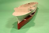
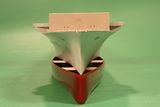
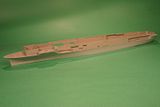
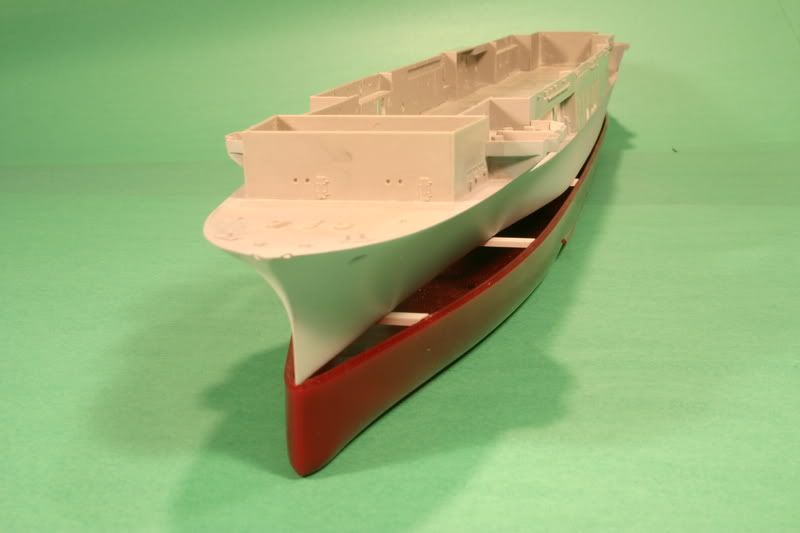
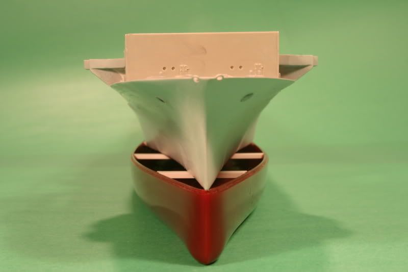
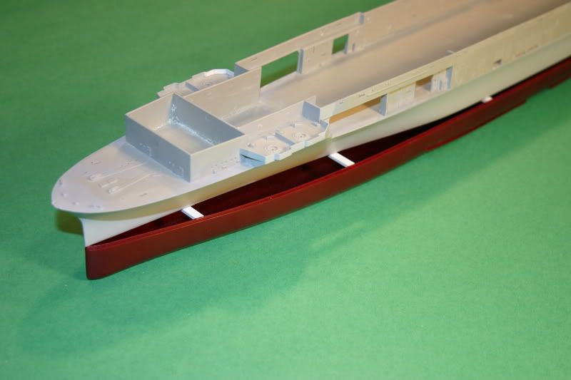
(I've seen a number of posts now where folks have mentioned trying to correct the Trumpeter hull. The following is a bit long (it was written as an article, but never published). It describes the method I used to rebuild the hull. I am posting it here, with the hope that someone may find it useful. The photos show the corrected upper hull placed on the kit's mishapen lower hull to illustrate the scope of the errors.)

Correcting Trumpeter's CV-8 HORNET Hull


“…the hull is where you begin when you build either a ship or a model and it has to be true.”
-Robert Sumrall


Trumpeter’s hull, while dimensionally accurate at the hangar deck level, is misshapen in cross-section throughout its length due to excessive beam at the waterline. The kit completely misses the radical tapering of the lower hull towards the bow and stern. This results in errors in all of the complex curves of the hull sides. The error is greatest in the forward third of the hull, and it is this area which critics refer to when they state that the shape of the “bow” is inaccurate.

A bit about the prototype. The design of a warship must balance three elements; speed, protection, and striking power. With the CV-5 YORKTOWN class, the U.S. Navy elected to maximize striking power (largest possible flight deck) and speed (large propulsion system). In order to stay within the specified displacement certain compromises were required in the hull design. Norman Friedman's superb U.S. Aircraft Carriers: an Illustrated Design History discusses in detail how this was accomplished. To accommodate the desired length of the flight deck while retaining adequate mid-ship beam for the machinery spaces it was necessary to reduce the hull’s volume at the bow and stern. The beam of the lower hull was drastically reduced both fore and aft, resulting in sharp hull lines that were a key characteristic of the class. While aesthetically pleasing, it rendered them vulnerable to flooding and stability problems. (The two war losses, YORKTOWN and HORNET, succumbed primarily to torpedo damage.)

Comparison of the model with a waterline plan-view of the real hull reveals gross errors in the kit. The beam is excessive at the waterline at every point, resulting in hull sides that are much too vertical. Beneath the forward hangar the curve of the waterline should reverse and become concave. It is here that the dimensional errors are greatest, exceeding 1 1/2 inches (that’s 45 feet in 1/350 scale). This area of the hull is more than twice as wide as it should be. How did Trumpeter get it so wrong? Speculation has it that they copied Blue Water Navy’s 1/350 resin HORNET which suffers from similar hull shape inaccuracies. Jeff Herne and Michael Vorrasi did a comparative review, concluding that while the Trumpeter kit is not an exact copy, the similar errors make it likely that the BWN kit was used as a reference in lieu of actual documentation.

If Trumpeter wanted a 3-D reference, they would have been much better off looking at the old Revell box scale kit. Its details are crude but the hull is outstandingly accurate. It’s currently re-released (Revell-AG kit 5014 “Battle of Midway Carrier”), so if you can get your hands on the old dinosaur, it’s a wonderful reference.

Defenders of the kit have rationalized that the errors are minor, are not noticeable, and are very difficult to fix. Unfortunately, only the last is true. If they really were minor, fixing them would be easy, it is difficult because the errors exceed the thickness of the plastic.. As for being unnoticeable, once you are aware of what the hull should look like the inaccuracies became impossible to ignore. Accepting them is a personal decision, and many fine modelers have done so. But rationalizations will not correct the flaws and so I undertook to rebuild.

I built a waterline model, so I won’t address the lower hull section. It would be difficult to salvage the kit part; I think a scratch built hull bottom would probably be required.

The magnitude of the error varies along the hull’s length, so different construction techniques were employed where appropriate. Mid-ship, the sides should not be vertical, but flare from the waterline up. They can be reshaped, and with some good backing the kit plastic is just thick enough to handle this. The stern is more complicated, since correcting the outline here will require completely grinding through the kit plastic in places. Solid filler will need to be packed inside. The forward hull has the greatest errors. Simply put, they are beyond correction. All of the hull below the forward hangar and forecastle decks will be lost in the rework of this area, and must be fabricated from scratch.

Materials are a matter of preference. I like to work with styrene and cynoacrylate (superglue), but epoxy putties and wood could be used instead and the techniques would be approximately the same.

From the stem, measure back 12” along the hull sides. Make a vertical mark here on each side. (Everything forward of this mark from the hangar deck down will have to go, but don’t cut yet.) Next, take the hull waterline plate and on its bottom mark out the correct waterline outline. Scribe an accurate centerline and cross sections at right angles. Attatch it to the aft part of the hull, up to the vertical marks you made on the hull sides. Do not bond it to the forward part, since that will be cut away.

From the middle working aft, start reinforcing and bracing the inside of the hull sides, particularly at the bottom where the waterline plate meets the hull. Be very generous. I used lengths of Evergreen .250x.125 styrene, bent to follow the kit’s contours and bonded with liberal applications of gap-filling superglue. Test fit your hangar deck sections frequently, to make sure there is no interference and to insure that your reinforcement isn’t pulling anything out of alignment. Keep working all the way back to the stern. Here you must add extra depth and height to this interior “planking”. Alternatively, you could build up this area with epoxy putty, but I like the strength that big slabs of styrene provide.

Trim the waterline plate to its correct contours This is harder with the plate in place on the hull, but the advantage is that you’ve added a lot of strength and rigidity, and you can still beef up the interior structure if it looks to be inadequate.

Attach the hangar decks now for still more rigidity, because it is time to cut loose the forward hull. Starting at the bow below the forecastle deck, on each side make a long horizontal cut just below the deck level, back to a point where it intersects with the hangar deck. Here you’ll need to make a slight vertical jog, and then continue to cut back to those vertical marks you made at 12 inches. Everything forward of this between the waterline plate and decks can now go bye-bye.

For the new forward hull I considered using traditional building methods such as bread-and-butter and plank-on-frame. Eventually I opted for a compromise that used features of both. I built a frame using bulkheads attached to a centerline, then built up bread-and-butter style stacks of styrene in between them. This technique ensured accuracy without compromising strength or rigidity.

Hull plans should be consulted to make the cross-section bulkheads from .040 sheet styrene. These will ensure level decks and true hull alignment, as well as establishing the shape of the hull sides. Make sure everything is level and square before continuing. Lengths of .250x.250 styrene were then stacked in butcher-block fashion, in “step” from the waterline to the deck to conform roughly to the curve of the hull sides. These can be gently bent laterally to conform. They should project beyond the bulkhead dimensions externally. Don’t hesitate to double them internally as necessary. The 5”/38 gallery sponsons will be reshaped so provide adequate internal backing. The correct curve of the hull will require that the outer edges of the forward hangar and fore decks actually form part of the new hull, so be sure they are firmly joined to the styrene stack. Use a solid block of styrene for the upper bow. To ensure a sharp, sturdy stem, make this from a strip of brass stock.

With a cutting head in a motor tool, rough shape the hull by carving away the overhangs where the butcher blocks project from the hull sides. Then put a sanding drum on a 3/8” adjustable speed drill, and at slow speed, shape things further, using the bulkheads as a guide. Shape the remaining kit hull sides to blend in. The sides of the mid-ship section should be less vertical, with a slight “tulip” flare just below hanger deck level. As you move aft the new waterline profile will establish how the vertical curves of the stern should taper. There should be a “crease” where the aft 5”/38 gallery sponsons join the hull at the hangar deck level. External cross-section templates will help establish the correct shapes at specific points and maintain symmetry. Refer to photos of the real ship and “eyeball” the kit at matching angles to determine shapes between these points. I can’t emphasis enough how useful the Revell hull is as a 3-D reference.

Do the final shaping by hand, using progressively finer grit sandpaper wrapped on curved shapes to match the hull (I find old C and D cell batteries and hobby paint bottles useful).

Fill…. sand…. prime…. sand….re-fill….sand….re-prime….sand….sand…..sand…..

Really stupid mistakes I made that you should avoid:

1) I initially underestimated how much of the forward hull would be completely lost, and had to splice in extra styrene sections. The directions above account for my error and should save you from this.
2) I didn’t always provide adequate backing, and ground right through my “corrections”. More splicing of styrene. Do not skimp.
3) When stacking the styrene to build the forward section, keep everything “square” and level. Do not be tempted to angle the styrene blocks to conform to the angles of the hull sides. You’re not building plank-on-frame. It’s more important to get good solid joints, or you’ll pay by doing a lot of filling.

One other weakness of the kit is the fit of the 5”/38 galleries. The splinter shielding should align with the hull contours, so I attached them and the adjacent hanger bulkheads at this point, and re-worked the joints to achieve a smooth transition.

New hawse pipes can be made by drilling holes and inserting plastic tube. Fittings such as degaussing cables, external fuel lines, and portholes (or their cover plates) must be added. These details will be different depending on which of the three ships you are modeling and the specific time frame. As built, all three ships were fitted with a forward hangar deck catapult, which accounts for the sponsons on the hull at that location. HORNET and ENTERPRISE had these removed after Midway.

The way I went about it is certainly not the only way it can be done, but I am satisfied with the results. Is it worth the effort? For me, yes. The payoff comes when I look at the model, and see the sleek lines of the real ship rather than a bulky chunk of plastic.
Image
Image
Image
Image


Top
  
Reply with quote  
 Post subject:
PostPosted: Sun Mar 25, 2007 10:07 pm 
Offline
User avatar

Joined: Sat Feb 26, 2005 7:32 pm
Posts: 960
Location: Seattle, Wa.
Guys, Thank you for your kind words. It was a fun Build and was my first attempt at trying to show propellers in motion. That turned out ok but still needs a little more work.
We sure can get a lot of help on this site for our builds. That sure helped me with my build.

TA

Gordon


Top
 Profile  
Reply with quote  
 Post subject:
PostPosted: Mon Mar 26, 2007 9:08 am 
Quote:
So, OK. Here's another question: what is the purpose of the pair of probably tubular arms projecting horizontally and athwartships on the port side of HORNET, midships? They appear to be maybe 30' long, and they have a support rod to keep the horizontal arm, well, horizontal. They show in both the pictures of HORNET driving through the heavy seas just prior to Doolittle's launch, and they are quite apparent on closeups of the ship being abandoned at Santa Cruz. They look like a supporting structure for horizontal antenna wires, maybe 70' long and parallel to the ship's centerline. I assume they could be HF antennae, but I don't see anything clearly strung between the arms. I don't recall seeing any pictures of ENT or YKTN with a similar fitting. Any thoughts? /

John,

I looked at photo 02/020816 on NavSource to check the locations, and then went to the Maryland Silver plan book. The drawings on page 45 and 46 show what appears to be these fittings. Page 34 has a notation for "emergency antenna outrigger" at the forward of the two stations.
I would be only guessing, but it lends weight to your supposition. Anybody know for sure?


Top
  
Reply with quote  
Display posts from previous:  Sort by  
Post new topic Reply to topic  [ 918 posts ]  Go to page Previous  1, 2, 3, 4, 5, 6, 7 ... 46  Next

All times are UTC - 6 hours [ DST ]


Who is online

Users browsing this forum: petr.haluza, TZoli and 62 guests


You can post new topics in this forum
You can reply to topics in this forum
You cannot edit your posts in this forum
You cannot delete your posts in this forum
You cannot post attachments in this forum

Jump to:  
Powered by phpBB® Forum Software © phpBB Group