The Ship Model Forum

The Ship Modelers Source
It is currently Tue Apr 16, 2024 2:41 am

All times are UTC - 6 hours [ DST ]


Post new topic Reply to topic  [ 274 posts ]  Go to page Previous  1 ... 10, 11, 12, 13, 14
Author Message
PostPosted: Thu Mar 04, 2021 11:15 pm 
Offline
User avatar

Joined: Thu Apr 03, 2008 10:07 am
Posts: 236
Location: Pittsgrove, New Jersey
Found IT


Attachments:
CVLStarboardCloseUp-5Jun430.jpg
CVLStarboardCloseUp-5Jun430.jpg [ 85.57 KiB | Viewed 25188 times ]
Top
 Profile  
Reply with quote  
PostPosted: Fri Mar 05, 2021 4:34 pm 
Offline
User avatar

Joined: Sat Apr 22, 2006 5:49 pm
Posts: 51
Location: NJ
Oh man that's awesome, thanks for the great description and pic. I guess Hasegawa is trying to represent the hose reels (minus the two vertical tanks) in their 1/350 scale CVE 73? I have them circled in red in the picture below? I'm just wondering if I can use that as a reference to determine location and the number of them present. In your picture they look to be about the size of 5 gallon buckets, correct? Also, were they a standard design from ship to ship or did they differ on different classes of ship?

Image


Top
 Profile  
Reply with quote  
PostPosted: Fri Mar 05, 2021 10:56 pm 
Offline
User avatar

Joined: Thu Apr 03, 2008 10:07 am
Posts: 236
Location: Pittsgrove, New Jersey
This photo was posted to me by Rick Davis. I was doing a diorama for a Vet who was on my Dad's ship, USS CVL 26 Monterey. He was a first loader on 40mm Mount #10. Here is that build:

viewtopic.php?f=59&t=76455&hilit=1%2F32+bofors+40mm+oneslim&start=20

The photo was a wide shot that showed the aft half of the ship fitting out. It was blown way up to show the mount. Being a large crop the angles are distorting the size. My guess is 25 or 30 gallons. I'm not really sure, don't know how the system worked .

Hope this Helps,

BobW


Top
 Profile  
Reply with quote  
PostPosted: Thu Mar 11, 2021 6:53 pm 
Offline
User avatar

Joined: Sat Apr 22, 2006 5:49 pm
Posts: 51
Location: NJ
I found a nice shot of what I believe to be what you were talking about Bob. Just to the left and below the nose of the plane is a vertical tank, but there's only one...maybe the other one is behind it(?). The oddly shaped circles with the hoses draped on them are what I assume Hasegawa is representing in the molding of their 1/350th scale Gambier Bay (see the picture in my post above), and presumably the hose reels you mentioned. This shot is from the NavSource site, and is of CVE 57, U.S.S. Coral Sea. I had seen it in one of many times I combed that site's pictures but thanks to your explanation, I know what I'm looking at.

Image


Top
 Profile  
Reply with quote  
PostPosted: Fri Mar 12, 2021 12:21 am 
Offline

Joined: Mon Jan 10, 2005 11:02 am
Posts: 10454
Location: EG48
If you're just looking for photos I may have some, but you'll need to wait until the weekend for me to have enough time to go looking.

_________________
Tracy White -Researcher@Large

"Let the evidence guide the research. Do not have a preconceived agenda which will only distort the result."
-Barbara Tuchman


Top
 Profile  
Reply with quote  
PostPosted: Fri Mar 12, 2021 8:06 am 
Offline
User avatar

Joined: Fri Dec 12, 2008 12:44 pm
Posts: 1774
Location: Herk-de-Stad, Belgium
jep1210 wrote:
I found a nice shot of what I believe to be what you were talking about Bob. Just to the left and below the nose of the plane is a vertical tank, but there's only one...maybe the other one is behind it(?). The oddly shaped circles with the hoses draped on them are what I assume Hasegawa is representing in the molding of their 1/350th scale Gambier Bay (see the picture in my post above), and presumably the hose reels you mentioned. This shot is from the NavSource site, and is of CVE 57, U.S.S. Coral Sea. I had seen it in one of many times I combed that site's pictures but thanks to your explanation, I know what I'm looking at.

Image

Maybe not very respectful , but these really look rather like the proverbial 'garden hose wall mount'. Should not be too difficult to scratch these yourself.
Attachment:
garden-hose-holder-wall-mount.jpg
garden-hose-holder-wall-mount.jpg [ 120.9 KiB | Viewed 24945 times ]

_________________
"I've heard there's a wicked war a-blazing, and the taste of war I know so very well
Even now I see the foreign flag a-raising, their guns on fire as we sail into hell"
Roger Whittaker +9/13/2023


Top
 Profile  
Reply with quote  
PostPosted: Fri Mar 12, 2021 10:11 am 
Offline
User avatar

Joined: Sat Apr 22, 2006 5:49 pm
Posts: 51
Location: NJ
Tracy White wrote:
If you're just looking for photos I may have some, but you'll need to wait until the weekend for me to have enough time to go looking.


That would be great, thanks. I have some time before I get to that area but as usual for me I tend to get hung up on details that I'm not ready for and it has a tendency to stall my projects. :huh: I'm really just looking for details to busy up the catwalk area on my Bluejacket Gambier Bay build, and what happens to the lines the run vertically up the sides of the hull. Thanks to BobW"s explanation I have a bit of a better understanding of those. It's a great kit but lacks any details in this area so I'm trying to avoid that sparse look that can happen on some scale model builds, we'll see how successful I am. :cool_2:


Top
 Profile  
Reply with quote  
PostPosted: Fri Mar 12, 2021 10:12 am 
Offline
User avatar

Joined: Sat Apr 22, 2006 5:49 pm
Posts: 51
Location: NJ
[/quote]
Maybe not very respectful , but these really look rather like the proverbial 'garden hose wall mount'. Should not be too difficult to scratch these yourself.
Attachment:
garden-hose-holder-wall-mount.jpg
[/quote]

You're not wrong, that should be fairly easy to scratch.


Top
 Profile  
Reply with quote  
PostPosted: Thu Dec 15, 2022 10:30 pm 
Offline

Joined: Tue Jan 06, 2015 5:28 pm
Posts: 96
Does anyone know if there is a copy of Commencement Bay class Booklet of General Builder's Plans floating around anywhere?

_________________
USS WASP CV-7 VIDEO SERIES

Episode 05: Builder's Trials
Guided Tour1: Hangar Deck

ESSEX CLASS TIMELINE
USS Ticonderoga CV-14 Operational History
USS Shangri La, 1945 in Color


Top
 Profile  
Reply with quote  
PostPosted: Sat Sep 09, 2023 7:41 pm 
Offline
User avatar

Joined: Sun Jul 03, 2011 5:10 pm
Posts: 274
Location: Windsor Junction NS
Ahoy,

Digging through this thread, I've found that there are some options on the web for finding Nabob plans, but, when looking at them, they do not have a complete set of hull lines included, only partial, with only 7 frames present.

Frame 170, 142, 120, 100, 78, 55 and 13.

That seems...inadequate to build a decent hull form to me.

Does anyone have access to other plans that may have more detail?

_________________
ICBM Address: 44:78N 063:63W

Ex RCN, HMC Ships Gatineau, Athabaskan, Charlottetown, St. John's, Montreal, Charlottetown, Summerside, Montreal.


Top
 Profile  
Reply with quote  
PostPosted: Sat Sep 09, 2023 8:03 pm 
Offline
User avatar

Joined: Sun Jul 03, 2011 5:10 pm
Posts: 274
Location: Windsor Junction NS
DavidP wrote:
would sheer & body plan work for you?


Certainly wouldn't hurt.

_________________
ICBM Address: 44:78N 063:63W

Ex RCN, HMC Ships Gatineau, Athabaskan, Charlottetown, St. John's, Montreal, Charlottetown, Summerside, Montreal.


Top
 Profile  
Reply with quote  
 Post subject: HMS Searcher
PostPosted: Tue Nov 14, 2023 5:45 am 
Offline
User avatar

Joined: Tue Sep 26, 2006 5:15 am
Posts: 637
Location: England
I'm looking to resurrect my build of HMS Searcher based on the Skywave Bogue model. Looking at the photo of HMS Searcher on wiki, I can see what look like twin 20mm guns on the bow and possibly another one on the port side midships 20mm gallery, just forward of the funnel. I have found a site that claims she had more twin 20mm fitted, which seems plausible given the photo evidence. Does anyone know anything about her 20mm outfit? I believe the photo to be of her in 1944, when she was operating as a 'fighter' carrier with Wildcats. Also, would her 4in single guns be US or British guns?

thanks
Mike


Top
 Profile  
Reply with quote  
PostPosted: Tue Nov 14, 2023 12:26 pm 
Offline
User avatar

Joined: Tue Sep 26, 2006 5:15 am
Posts: 637
Location: England
DavidP wrote:
are you certain those are twin 20mm mounts & not twin 40mm mounts as there appears to be no shields normally associated with 20mm mounts?
https://www.navsource.org/archives/03/0302208.jpg
https://www.navsource.org/archives/03/0302201.jpg
https://www.navsource.org/archives/03/022.htm


Yes, twin Oerlikons. British power twin Oerlikons were totally different mounts and didn't have the shields that manual Oerlikons had


Top
 Profile  
Reply with quote  
PostPosted: Mon Dec 11, 2023 7:32 pm 
Offline
User avatar

Joined: Sun Jan 16, 2005 2:06 am
Posts: 269
Location: Seattle, WA
Sorry to be late to the discussion here, but the topic of British CVEs is near and dear to my heart.
When there is reference to "twin 20mm" on a British CVE, they are talking about the British Mk V power operated mounts, rather than the hand-operated twin 20 used by the USN. This mount is identified by a slanted operator's station on one side and the two guns offset to the other side.
https://www.shapeways.com/product/D8HSK43ZA/1-56-twin-20mm-oerlikon-powered-mkv-mount-25-ordm

The mount is really visible on the bow in the first photo that DavidP posted - https://www.navsource.org/archives/03/0302208.jpg. As near as I can tell, when the twins were put in the bow location, they were also mounted around the deck edges, swapping three singles out for two twins. That still left a couple of singles.

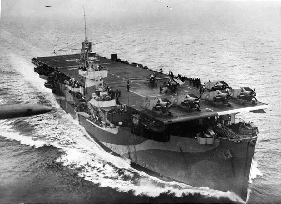
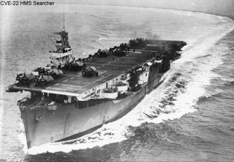
Searcher is an odd critter, because she was a member of the earlier "Attacker" class of eleven ships, but she eventually received the weapons upgrades of the later class. The later eleven "Ruler" class were originally configured with eight twin 40mm mounts, while the Attackers started out with only four twin 40s, one on each corner. Again, that photo clearly shows two 40mm mounts forward of the island, so she was updated to have eight twin 40mms. The power operated twin 20s would have been a part of that update also. My guess is that those changes would have happened during a dockyard period in New York between 1 May 44 and 2 July 44.

And like all of the British CVEs, her flight deck was extended before going into British service. A twelve foot extension at the after end is only a whopping 5mm in 1/700 scale, but it is a fun way to differentiate the USN from RN CVEs. There are drawings of the British CVEs, but they were created at the time of handoff from the US yard to the RN, so they don't show the RN changes that were implemented before going into service. I haven't figured out how to tell where the external fuel lines were, as they seem to vary from ship to ship.

And the 4" guns were the US pattern.

I will now stand by for corrections. :-)
Rick

_________________
On the workbench:
1/700 Jouett - JAG
1/700 Lupo - Delphis
1/700 Ulsan - Kobo Hiryu
--and dozens more


Top
 Profile  
Reply with quote  
Display posts from previous:  Sort by  
Post new topic Reply to topic  [ 274 posts ]  Go to page Previous  1 ... 10, 11, 12, 13, 14

All times are UTC - 6 hours [ DST ]


Who is online

Users browsing this forum: No registered users and 37 guests


You can post new topics in this forum
You can reply to topics in this forum
You cannot edit your posts in this forum
You cannot delete your posts in this forum
You cannot post attachments in this forum

Jump to:  
Powered by phpBB® Forum Software © phpBB Group