Foeth_ wrote:
There're a few minor issues.

The degaussing cable has a double run around both the bow and the stern:
http://blog.ontheslipway.com/wp-content/uploads/2008/07/degauss_10.jpgI've based my work on the file :
http://hmshood.com/hoodtoday/models/trumpeter/bowfairings.gif specified by Franck and i had not realized there were two parts... Ready to correct (not fine to do)
Quote:
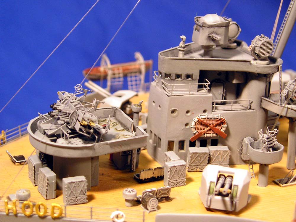
The mushroom vents around B & X turret, plus those near the conning tower were placed much higher (check pics of the late version Hood)
Can you give me an order of height 'cause i've not found on the site
Quote:
On the bridge, between the HACS director and the 5.5" director, you have an entirely gray area. You should be able to see something on the other side on either side on the vertical leg of the tripod running through the entire bridge structure.
Corrected
Quote:
You miss a radar antenna on the top rangefinder.
Corrected
Quote:
It seems that the air intake aft of funnel #1 should go a bit back?
Don't really think it's back.
I stay it there for the moment but i haven't seen a great difference between my drawing and pictures of the Hood
Quote:
Color of the anchor: probably not that color, but ship gray with dirt.
I completly agree with you. The colors are the last touch before adding the shaddowing.
It's easier for me to work. I suppose a good dark black....
Here a small preview of the Hood will be.

I'll have to correct my shaddowing to obtain a better grey/blue
When the profile will be finished, i'll go to find the good colors references for this.
Sincerely
Jean


