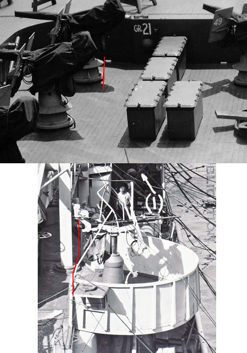
These are great photos, and the last one illustrates very well the point I'm struggling with: it also raises a question.
Is the gunner strapped into the gun? That is, are his shoulders "mated" to the shoulder rests with some sort of harness? In the last image, the gunners balance would cause him to be holding himself up using his hands on the triggers. This in turn seems like it would be difficult to keep the gun trained on the target (I'm assuming the gun is balanced such that it does not take much effort to move - but that could be a bad assumption).
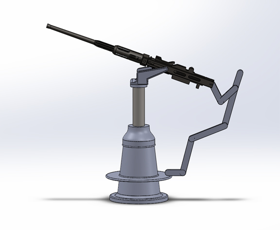
Here's where I'm having trouble. The image below shows a very to-scale (incomplete - missing the cradle, shoulder rests, other things) gun/mount, with a body puppet (using my basic measurements - I'm 6'1"). Even with the mount fully elevated, the angle of the gunners body seems impossible for any sort of actual use... unless the gunner is strapped to the gun. Lowering the gun would make it even more awkward.
Anyway, that is why I raised the question in the first place - I just don't see how this disk could be useful as a stand: but then, I've never fired a gun this large :
The gunner is strapped into the shoulder stock. The purpose isn’t to make sure he doesn’t duck. It is to allow him to better use the muscles of his legs and torso to swing the gun.
My guess is the disk on the pedestal allows the gunner to more comfortable fire over a larger range of elevations by giving him two different level to stand on. The wheel on the side of the pedestal adjusts the height of the trunnions. To fire the comfortably at high elevation, the trunnion of the gun need to be cranked up so the gunner doesn’t need to squat down and then look up to fire the gun. But if the trunnions is cranked all the way up, then the gunner will find himself standing on top toe to fire at low elevation. The disk gives the gunner a higher step to stand on so he can fire comfortable at low ekevation even if the trunnion is cranked up. This ensures in the heat of battle he or his loader does need to crank the trunnions up and down like crazy.


 ) with the purpose of the "stand". I would love to come up with a combat photo to confirm but that is really asking too much - for me, this question is resolved AND it makes sense.


