The Ship Model Forum

The Ship Modelers Source
It is currently Tue Apr 16, 2024 7:17 am

All times are UTC - 6 hours [ DST ]


Post new topic Reply to topic  [ 339 posts ]  Go to page Previous  1 ... 5, 6, 7, 8, 9, 10, 11 ... 17  Next
Author Message
PostPosted: Sat Jan 03, 2015 4:07 pm 
Offline

Joined: Sun Nov 14, 2010 4:54 pm
Posts: 329
Brooklyn/Cleveland hull differences:-

Hi,

Can anyone tell me what the differences were between the Brooklyn and Cleveland class hulls?

Was there a significant difference in hull form and were the transoms different? And were the shafts, propellers and A-frames different?

Any help, links or photos appreciated.

All the best
Sandy


Top
 Profile  
Reply with quote  
PostPosted: Sat Jan 03, 2015 7:53 pm 
Offline
User avatar

Joined: Mon Aug 06, 2007 6:29 pm
Posts: 1952
There were significant similarities and equally significant differences. If you have studied the history, you should remember the evolution from one to the other. The original Brooklyn hull carried over into the very similar St Louis hull. (Close, but not identical.) The original changes made to the St Louis hull to adapt it into the Cleveland were first, a very slight increase in beam, second, the machinery spaces were moved forward moving the side armor with it. And third, the corners of the stern were rounded at the main deck level. After Cleveland had been laid down, the light AA requirement was increased, so to compensate the lower edge of the armor belt remained in the same place but the belt was tilted outward rather than inward, increasing the beam at the top of the belt. This created a "crease" or "knuckle" in the side at the top of the belt.

The following Navsource photos show the original Brooklyn hull side, flat from the bottom of the belt to the main deck level.
Brooklyn: http://www.navsource.org/archives/04/040/0404022.jpg
Brooklyn: http://www.navsource.org/archives/04/040/0404027.jpg
Boise (in Argentine service): http://www.navsource.org/archives/04/047/0404726.jpg

Contrast that flat side with these three launch photo of Cleveland class. The increased tumblehome above the armor is obvious.
Denver: http://www.navsource.org/archives/04/058/0405814.jpg
Atlanta: http://www.navsource.org/archives/04/104/0410421.jpg
Dayton: http://www.navsource.org/archives/04/105/0410512.jpg

These two shots of Wilkes Barre show the crease at the top of the armor belt.
aft: http://www.navsource.org/archives/04/103/0410309.jpg
forward: http://www.navsource.org/archives/04/103/0410310.jpg

The Brooklyn transom was largely retained at and below the waterline, but rounding the upper corners made it a very complex shape. These shots of sterns show the excessive tumblehome on the aft corners.
Springfield: http://www.navsource.org/archives/04/066/04010706.jpg
Vicksburg: http://www.navsource.org/archives/04/086/0408608.jpg

The overall complexity can be seen in this shot of Oklahoma City being sunk. (There is a similar shot of Wilkes Barre in one of the early Warships volumes. Note how much the underwater shape resembles the Brooklyn stern shape.
http://www.navsource.org/archives/04/091/04010551.gif

One of the oddities in the Brooklyn to Cleveland series is the different positioning of the prop guards. On the Brooklyns, the guards were basically below the forward ends of the catapults. On the St Louis class, the guards were further forward (as a consequence of having unit machinery in the same more-aft compartments as the Brooklyns - that is why I said that the Brooklyn and St Louis hulls weren't quite identical). Then on the Clevelands, they were back to the forward ends of the catapults.
Philadelphia: http://www.navsource.org/archives/04/041/0404104.jpg
St Louis: http://www.navsource.org/archives/04/049/0404933.jpg
Wilkes Barre (again): http://www.navsource.org/archives/04/103/0410309.jpg

I hope this gives you what you need.


Top
 Profile  
Reply with quote  
PostPosted: Sun Jan 04, 2015 1:41 am 
Offline
User avatar

Joined: Sun Mar 07, 2010 12:01 am
Posts: 1645
Location: Corvallis, Oregon, USA
Brooklyn was 608 feet in length and Cleveland was 610 feet long - the slight increase apparently was due to rearrangement of the engineering spaces. Underwater there would have been significant differences in the hull openings.

As Dick J said, the main visible differences were the tumblehome and rounded stern.

The Clevelands were wider midships at the top of the armor belt (65 feet) than they were at the main deck level (62 feet). This was an expedient change to increase buoyancy to compensate for increased armor, engineering plant and anti-aircraft battery. Even so, the Clevelands were still top heavy and rolled a lot. The CLG modifications were even more top heavy and rolled badly in heavy weather. I speak from experience!

I have always loved tumblehome on ships - I guess there is some romantic tie to the wooden sailing ship days when tumblehome was common. It didn't look like a shoe box with one pointed end and the other blunt. And wooden decks!

The top of the Cleveland hull at the stern was a circular arc 32 feet diameter and below the waterline it was almost square like the Brooklyns. It is a very complex shape to model correctly. Here is a picture:

http://www.okieboat.com/Copyright%20ima ... 24%20C.jpg

The Cleveland propeller guards were positioned directly above the outboard propellers. I assume that is where they were with the Brooklyn and St Louis class ships.

The Clevelands had a second narrower armor belt below the water line mostly forward of the larger midships belt. This smaller armor belt extended outside the forward magazines. I don't have blueprints for the Brooklyns, but I don't see this smaller armor belt in drydock photos of the Brooklyns. Anyone know of this armor belt was on the Brooklyns or St Louis classes?

You can see this second armor belt here:

http://www.okieboat.com/Copyright%20ima ... 24%20C.jpg

Phil

_________________
A collision at sea will ruin your entire day. Aristotle


Top
 Profile  
Reply with quote  
PostPosted: Sun Jan 04, 2015 7:05 am 
Offline

Joined: Sun Nov 14, 2010 4:54 pm
Posts: 329
Hi Dick and Phil,

Thanks very much.

I have a 96th scale Brooklyn hull, but, having spent several hours last night reading the Okie boat website I was inspired to think about the Oklahoma City thanks in no small measure to the excellent 3D drawings on the site.

I may need to think again.

At one stage I was thinking of doing 'the missile cruisers' in 72nd scale but they would have been huge. This would have been the Oklahoma City, Colbert and Zeven Provincien. I have plans for the French and Dutch ship, but not the US one.

Thanks again.

All the best
Sandy


Last edited by sandy on Mon Jan 05, 2015 4:19 am, edited 1 time in total.

Top
 Profile  
Reply with quote  
PostPosted: Mon Jan 05, 2015 3:12 am 
Offline
User avatar

Joined: Sun Mar 07, 2010 12:01 am
Posts: 1645
Location: Corvallis, Oregon, USA
Sandy,

If you decide to build an Oklahoma City CLG-5 model (or a CL-91 model) let me know. I'll be glad to help - up to a point.

I have received several requests for 3D CAD drawings for use with 3D printers. My drawings will not work for this. The model is somewhere around 750-800 Mbytes so far, and it is only about 3/4 finished. I don't actually have a single file with all the parts right now. As it is, it takes 45-90 minutes to shade the individual superstructure drawings, and just working with huge files takes a great deal of patience. So I have used a lot of file size reduction tricks.

Most of the solids in the CAD drawing are actually not solids. Many are hollow shells, often with the not visible ends and back sides missing. 3D printers do not like such things!

The DesignCAD file format is incompatible with most other CAD programs. I can create DXF files but it is a very primitive file format and a lot of information is lost. However, I am a beta tester for DesignCAD and we should have STL file format output in the not too distant future. That will make the program an excellent and inexpensive 3D printer driver!

I have a few 2D drawings that I have generated from the 3D models. It is my intention to prepare a complete set of 2D drawings for the ship. In order to capture all of the detail I suspect it will take dozens of sheets. And the best part of a year to create them after the entire 3D model is finished - and that won't be before 2016 or 2017 (I have been working on it for 10 years already).

Still, I do have some drawings that would be helpful, many blueprints, lots of photos and information about other sources that are helpful.

But please don't ask me to stop the work I have planned in order to do something else. I just barely have enough free time to make progress on the model and I don't need any other diversions!

Phil

_________________
A collision at sea will ruin your entire day. Aristotle


Top
 Profile  
Reply with quote  
PostPosted: Mon Jan 05, 2015 4:43 am 
Offline

Joined: Sun Nov 14, 2010 4:54 pm
Posts: 329
Hi Phil,

Thanks for the reply. I have sent you a PM.

All the best
Sandy


Top
 Profile  
Reply with quote  
PostPosted: Wed Jul 08, 2015 5:00 pm 
Offline

Joined: Sun Nov 14, 2010 4:54 pm
Posts: 329
Just a question about the portholes on Helena and St Louis (and I assume the Brooklyn's as well).

As built, there seem to be two rows (decks) of portholes.

Early war, the lower portholes seem to be gone and appear to have been plated flush, while the upper row appear to have plates over them.

And then, later in the war, they were all plated flush.

Is this correct?


Top
 Profile  
Reply with quote  
PostPosted: Sun Jul 12, 2015 12:30 am 
Offline
User avatar

Joined: Mon Aug 06, 2007 6:29 pm
Posts: 1952
sandy wrote:
Just a question about the portholes on Helena and St Louis (and I assume the Brooklyn's as well).

As built, there seem to be two rows (decks) of portholes.

Early war, the lower portholes seem to be gone and appear to have been plated flush, while the upper row appear to have plates over them.

And then, later in the war, they were all plated flush.

Is this correct?

Early in the war, the lower row was permanently closed off and plates were welded flush with the rest of the plating. This also applied to a few of the upper row, but most of them were covered by plates that were not flush so that they could be reopened post-war. In Brazilian service, the cover plates are still visible (not flush) on St Louis's hull. On the Brooklyn's, the upper row of ports was left open early in the war. The four that were blistered (CLs 40, 41, 42 and 48) had the upper row completely covered by the blisters. Of the remainder, CL-43's upper ports remained open. The other two had theirs covered, but they were then uncovered when they were in sold for foreign service.


Top
 Profile  
Reply with quote  
PostPosted: Thu Dec 17, 2015 12:43 am 
Offline

Joined: Wed Nov 18, 2015 10:18 am
Posts: 79
I have looked at every pic I can find Kit reviews, maybe overlooked the answer here. Did the Helena have a visible armor belt at any point? I'm scratch building a hull.


Top
 Profile  
Reply with quote  
PostPosted: Thu Dec 17, 2015 9:37 am 
Offline
User avatar

Joined: Mon Aug 06, 2007 6:29 pm
Posts: 1952
If you are doing a waterline model, not much will show. I have referenced a Navsource photo here:
http://www.navsource.org/archives/04/050/0405029.jpg
Note the armor just below the boot topping forward. Amidships, over that machinery spaces, you can see the front of the belt just coming up through the boot topping, to just above the top of the boot. There was another lower strake of armor aft. So for a full hull model, yes, you need to add armor. For a waterline model, perhaps a thin strip at the waterline amidships.


Top
 Profile  
Reply with quote  
PostPosted: Fri Feb 12, 2016 8:45 pm 
Offline

Joined: Fri Jul 16, 2010 5:02 pm
Posts: 35
The USS Helena has been my favorite US ship since I read about her in my dad's navy history book in the early 60's. I made the early Revell model not knowing that it was not the ship I had read read about. I have read about it's incredible record in battle and have made the classics warship model but is nothing like the awesome models I've seen on these pages. Some of you may have already found this video but I was surprised to find this color film on You Tube of Helena and St. Louis.
https://www.youtube.com/watch?v=wM4kcoHeVtk
There are a couple of other videos taken from the Honolulu.

Scot Chiasson


Top
 Profile  
Reply with quote  
PostPosted: Sun Feb 14, 2016 3:47 am 
Offline

Joined: Wed Aug 05, 2015 9:25 am
Posts: 2256
Location: Los Angeles and Houston
Cajuntiger wrote:
The USS Helena has been my favorite US ship since I read about her in my dad's navy history book in the early 60's. I made the early Revell model not knowing that it was not the ship I had read read about. I have read about it's incredible record in battle and have made the classics warship model but is nothing like the awesome models I've seen on these pages. Some of you may have already found this video but I was surprised to find this color film on You Tube of Helena and St. Louis.
https://www.youtube.com/watch?v=wM4kcoHeVtk
There are a couple of other videos taken from the Honolulu.

Scot Chiasson


They have a rather long series of videos of old film taken either onboard, or of the Helena and St. Louis.

Thanks a lot for posting these.

It is a shame that the USN and US Military did not think to document these ships more fully for posterity.

This is an era that the world should not forget.

MB

_________________
OMG LOOK! A signature

Working on:


1/700 (All Fall 1942):
HIJMS Nagara
HIJMS Aoba & Kinugasa
USS San Francisco
USS Helena
USS St. Louis
USS Laffey & Farenholt
HIJMS Sub-Chasers No. 4 - 7
HIJMS Sub-Chasers No. 13 - 16


Top
 Profile  
Reply with quote  
PostPosted: Sun Dec 04, 2016 3:38 pm 
Offline

Joined: Mon Jan 07, 2008 10:15 pm
Posts: 953
Hi Gang,
I came across some film footage of Brooklyn class cruisers during summer/fall 1941 and discovered a very odd feature on the deck of one of the ships. Notice the circles around the #1 and #3 turrets. This is a feature I have never seen before. Anyone have any ideas what this is all about?
Image

This footage also shows either USS Helena or USS St. Louis wearing MS-11. Can anyone positively identify which it is?
Image

Thanks


Last edited by Jeff Sharp on Sat Aug 12, 2017 6:31 pm, edited 2 times in total.

Top
 Profile  
Reply with quote  
PostPosted: Mon Dec 05, 2016 12:38 am 
Offline
User avatar

Joined: Sun Mar 07, 2010 12:01 am
Posts: 1645
Location: Corvallis, Oregon, USA
This is a long shot guess. On the OK City (Cleveland class with the same 6"/47 turrets as the Brooklyn class) we put down plywood sheets on the deck when we were on the gun line in Vietnam doing gunfire missions. This was to protect our pretty holystoned white teak wood decks from the impact of the shell casings that were ejected out of the rear of the turrets.

On the super elevated turrets on the Brooklyns (#2 and #4) and Clevelands (#2 and #3) the shell casings dropped out of the bottom of the turret. They sometimes carried a net under the rear of the turret to catch the shell casings before they hit the decks.

The circles in the photo are about where the shell casings would hit the deck behind the #1 and #3 turrets.

Phil

_________________
A collision at sea will ruin your entire day. Aristotle


Top
 Profile  
Reply with quote  
PostPosted: Mon Dec 05, 2016 3:21 pm 
Offline

Joined: Mon Jan 07, 2008 10:15 pm
Posts: 953
Thanks Phil, that seems like a very logical guess.


Top
 Profile  
Reply with quote  
PostPosted: Sat Dec 10, 2016 7:38 pm 
Offline

Joined: Mon Jan 07, 2008 10:15 pm
Posts: 953
I was able to locate another example of rings around the turrets. Here is USS Honolulu with a ring around her #3 turret.

Image


Last edited by Jeff Sharp on Sat Aug 12, 2017 6:32 pm, edited 1 time in total.

Top
 Profile  
Reply with quote  
PostPosted: Sat Dec 10, 2016 8:53 pm 
Offline

Joined: Wed Aug 05, 2015 9:25 am
Posts: 2256
Location: Los Angeles and Houston
Jeff Sharp wrote:
Image


Something struck me as odd in this image.

The turrets are really dark, yet the deck is bare teak (white - lighter colored).

Is this a Measure 1 or 4?

Because I didn't think that the Measures 11 or 21 allowed for an unpainted deck.

MB

_________________
OMG LOOK! A signature

Working on:


1/700 (All Fall 1942):
HIJMS Nagara
HIJMS Aoba & Kinugasa
USS San Francisco
USS Helena
USS St. Louis
USS Laffey & Farenholt
HIJMS Sub-Chasers No. 4 - 7
HIJMS Sub-Chasers No. 13 - 16


Top
 Profile  
Reply with quote  
PostPosted: Mon Dec 12, 2016 11:07 am 
Offline
User avatar

Joined: Tue Jan 11, 2005 1:40 pm
Posts: 8173
Location: New Jersey
Most likely Measure 1

_________________
Martin

"Tomorrow is the most important thing in life. Comes into us at midnight very clean. It's perfect when it arrives and it puts itself in our hands. It hopes we've learned something from yesterday." John Wayne

Ship Model Gallery


Top
 Profile  
Reply with quote  
PostPosted: Thu Dec 15, 2016 1:41 am 
Offline
User avatar

Joined: Sun Mar 07, 2010 12:01 am
Posts: 1645
Location: Corvallis, Oregon, USA
I was just looking at the blueprints for the USS Cleveland CL-55 and the main deck arrangement drawings show a "possible circle for mat for ejected cartridge cases" drawn around turrets #1 and #4. So apparently the circles shown in the photos are mats to protect the wood decks from ejected cartridge cases.

The drawings also show "possible circle of net for ejected cartridge cases" around superelevated turrets #2 and #3.

The circles around turrets #1 and #4 are much wider than the circles around the superelevated turrets #2 and #3. Cases were ejected out the back of the lower turrets and out the bottom of the higher turrets where the nets were hung.

Phil

_________________
A collision at sea will ruin your entire day. Aristotle


Top
 Profile  
Reply with quote  
PostPosted: Mon Feb 13, 2017 2:25 am 
Offline

Joined: Wed Aug 05, 2015 9:25 am
Posts: 2256
Location: Los Angeles and Houston
Picked up working on my St. Louis this evening.

And discovered that the bridge is all kinds of screwed up. So I am going to re-build it, since it is mostly the decking/platforms that are screwed up (and those are easily sanded off and replaced with a .01" Styrene that will look better, anyway).

I hope that you will pardon the brevity, I have been arguing with idiots all day who cannot do basic arithmetic (trying to teach basic set theory).

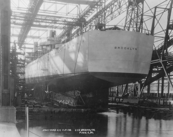
The kit is a Midship Model's 1/700 St. Louis.

The box says "1943," but I know that cannot be, because it has no twin 40mm tubs P/S before the bridge, and P/S Aft of the superstructure (before Turret #4). And it still has the 4 1.1" Tubs as well.

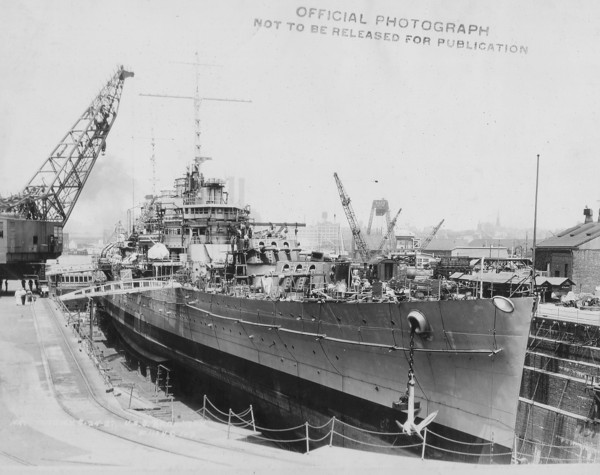
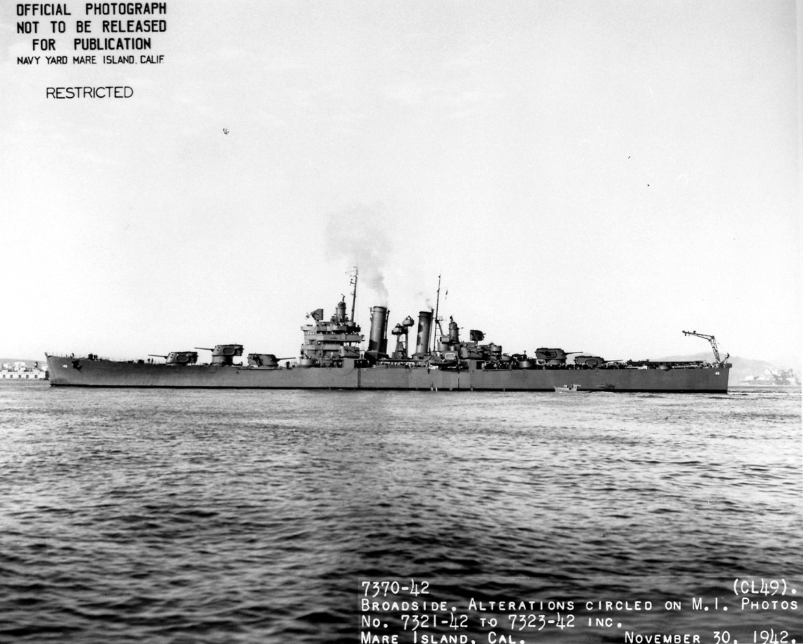
What I am trying to find out is if the back of the bridge was the same before/after the November 1942 Outfitting?

And..... What did that bridge look like?

I have been digging all over the internet (and Navsource), but can find nothing to show what the back of the bridge superstructure looked like.

Also, re: The Front of the bridge.

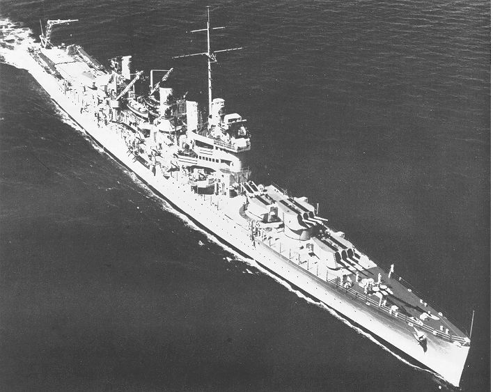
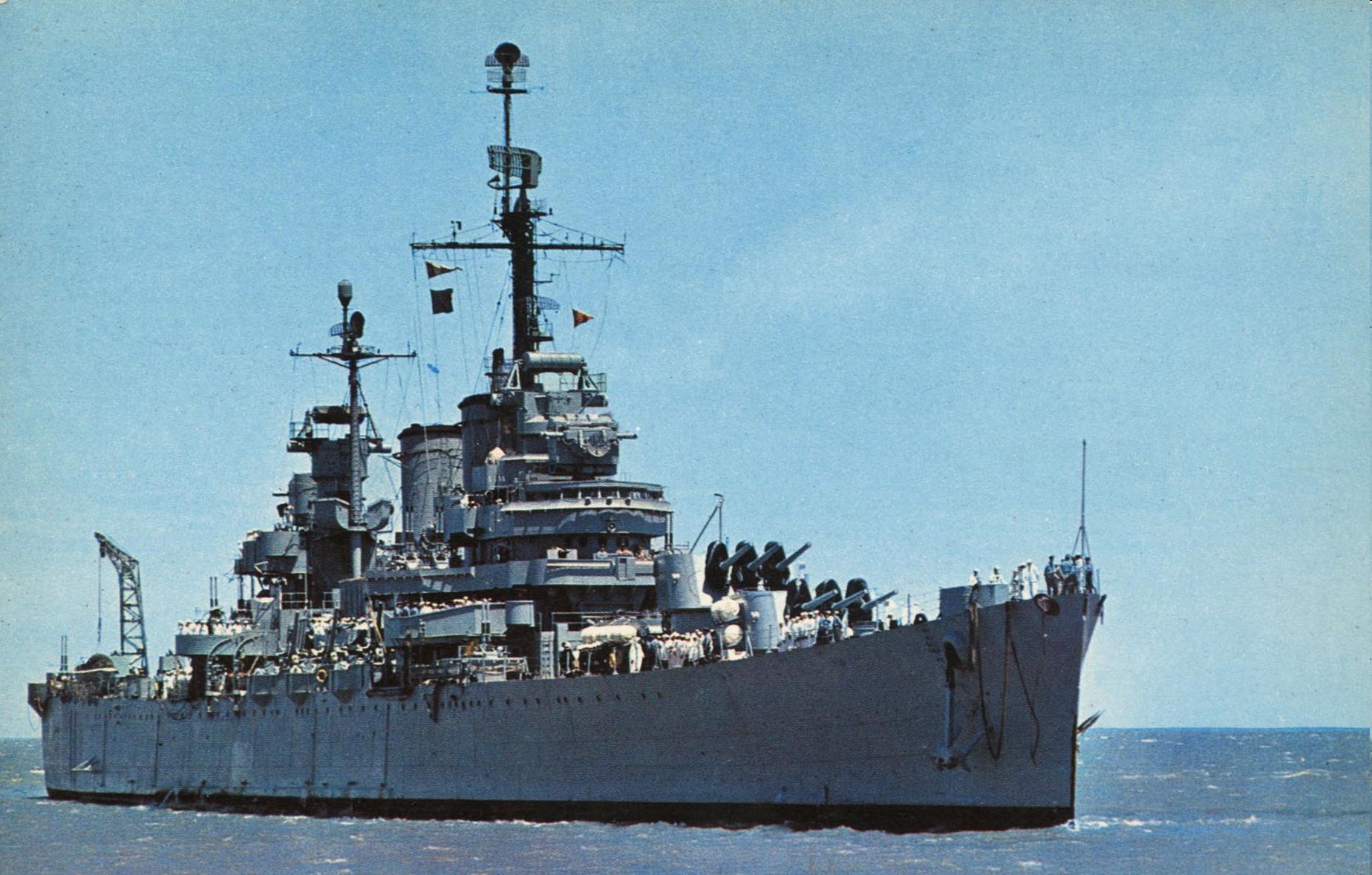
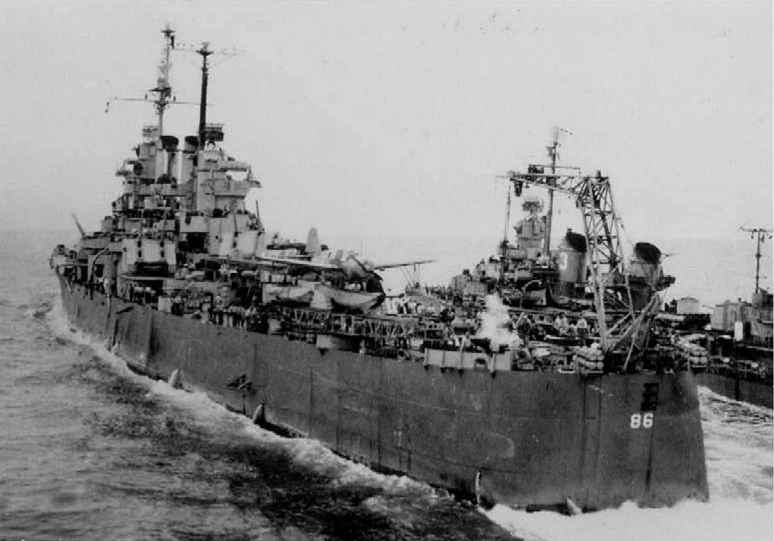
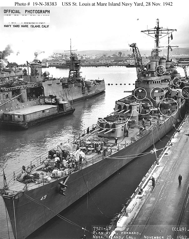
It looks like the lowest platform, around what I guess is the Conning Tower on the St. Louis, is flush with the front of the bridge face below it, re: This Photo:


http://www.navsource.org/archives/04/049/0404906.jpg

Is that correct?

That is a Nov 1942 Refit photo, but it looks like that platform remained the same (they have a March 1942 photo, but it does not show the area as well).

The Platform in question has what looks to be a kind of "upside down triangular" shape below it, that is flush with the forward bulwark of that platform.

Also, the sides of the bulwarks on that level..... They curve back into the P/S Bulwarks, rather than being a perfectly flat angle back to the P/S Bulwarks, do they not?

Now, moving up one level....

The platforms with the wind diverters on them.... They look to be about 10" - 12' or so below the level of the top of the Conning Tower. Is that right (as if there is a slight drop, or something)?

Also.... Does this deck and the Conning Tower look like they are the same height?

The Conning Tower doesn't look like it is shorter than the deck above it, does it? (I don't think it does, but the part says it is, and if they are the same height, then I need to add some height to the Conning Tower deck).


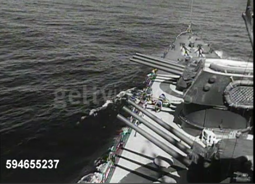
And as for the top platform, where the 1'1" mounts were....

How the freaking heck did the directors attach to the 1.1" Tubs? Or did they even? Are they mounted on a pillar on the deck behind the 1.1" tubs? What the heck does the deck back there look like?

Were there directors put in those director tubs? If so, what kind, please? (Mk. 51s available yet?)

How does the mast attach to the back of the bridge (if at all)?

Does the mast go all the way down to the base of the superstructure, or only to the 02 Bridge deck?

I think that is enough for the moment, as I do not want to overwhelm myself or others overly much when I begin to get answers.

Thank you for your patience....

MB

_________________
OMG LOOK! A signature

Working on:


1/700 (All Fall 1942):
HIJMS Nagara
HIJMS Aoba & Kinugasa
USS San Francisco
USS Helena
USS St. Louis
USS Laffey & Farenholt
HIJMS Sub-Chasers No. 4 - 7
HIJMS Sub-Chasers No. 13 - 16


Top
 Profile  
Reply with quote  
Display posts from previous:  Sort by  
Post new topic Reply to topic  [ 339 posts ]  Go to page Previous  1 ... 5, 6, 7, 8, 9, 10, 11 ... 17  Next

All times are UTC - 6 hours [ DST ]


Who is online

Users browsing this forum: No registered users and 35 guests


You can post new topics in this forum
You can reply to topics in this forum
You cannot edit your posts in this forum
You cannot delete your posts in this forum
You cannot post attachments in this forum

Jump to:  
Powered by phpBB® Forum Software © phpBB Group