The Ship Model Forum

The Ship Modelers Source
It is currently Tue Apr 16, 2024 8:21 am

All times are UTC - 6 hours [ DST ]


Post new topic Reply to topic  [ 474 posts ]  Go to page Previous  1 ... 19, 20, 21, 22, 23, 24  Next
Author Message
PostPosted: Sun Jul 17, 2022 4:38 pm 
Offline

Joined: Thu May 29, 2008 8:02 pm
Posts: 3825
Phil,

Actually, all but one CLEVELAND class unit (and both surviving BROOKLYN class units) eventually had the waist twin 40-mm mounts relocated to the fantail. Most units, those not modified while being built, were modified after the war during their overhauls, some were so modified just before they were mothballed. I determined that all but one CLEVELAND class unit had been so modified from reviewing 1950's mothball photos at Philadelphia NSY, San Francisco NSY, and Puget Sound NSY. All except for USS DENVER (CL-58) had fantail twin 40-mm mounts. The original "Round-Bridge" units had "non-standard" 40-mm mount configurations already.

Image


Top
 Profile  
Reply with quote  
PostPosted: Sun Jul 17, 2022 11:14 pm 
Offline
User avatar

Joined: Sun Mar 07, 2010 12:01 am
Posts: 1645
Location: Corvallis, Oregon, USA
Rick,

Thanks. I knew that the Clevelands that remained on active duty after the war were converted - and some were converted during the war if they had enough battle damage to get them into a shipyard. But I didn't know the mothballed ships were converted.

Phil

_________________
A collision at sea will ruin your entire day. Aristotle


Top
 Profile  
Reply with quote  
PostPosted: Mon Jul 18, 2022 12:41 am 
What is the CA without guns in the foreground?


Top
  
Reply with quote  
PostPosted: Mon Jul 18, 2022 10:38 am 
Offline

Joined: Tue Jun 14, 2005 6:23 am
Posts: 3697
Location: Bonn
USS Hawaii (CB-3)

_________________
Image


Top
 Profile  
Reply with quote  
PostPosted: Fri Jul 22, 2022 4:12 pm 
Offline

Joined: Wed Jan 19, 2005 7:14 pm
Posts: 72
Location: New Jersey
Rick E Davis wrote:
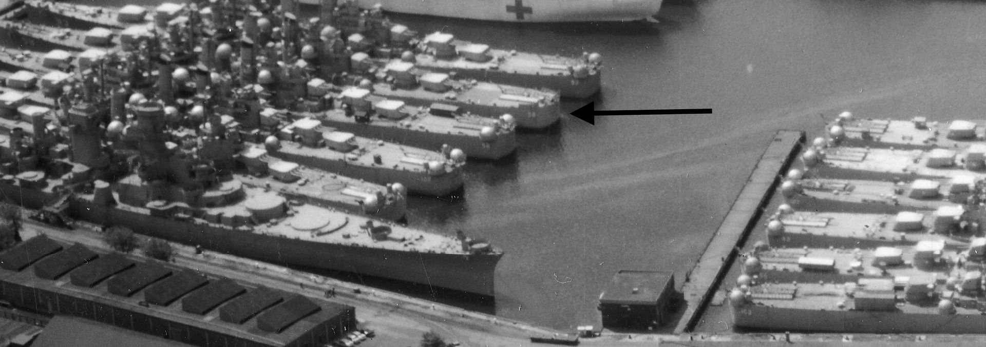
I only have one scanned image of USS SPRINGFIELD (CL-66) taken Post-WWII, dated 9 November 1948. See attached. SPRINGFIELD was decommissioned in January 1950, and underwent several changes. The major armament change made in 1946 was moving the waist twin 40-mm mounts to the fantail quarters and deleting one catapult (these were late-WWII authorized mods to the class for Anti-Kamikaze upgrades along with improved GFCS for the 40-mm guns). Authorized 40-mm armament was four quad and six twin 40-mm mounts (four on main deck at the corners of the superstructure and two on the fantail). But, at some point the forward two twin 40-mm mounts were landed to save crew size during "peacetime". But these mounts would be returned during wartime. Number of 20-mm guns is trickier. The 20-mm mounts would be Mk 24 twin mounts, but numbers were reduced to maybe only four mounts in the superstructure. I would need to do more digging in images of sisters still in service post-WWII to locate exact locations. But, they appear to be on the deck above the main deck just forward of the bridge and higher up in the aft superstructure.

Other changes were to the radars and RCM, which would need to be specific to dates desired to model.

Decks would be bare wood and the rafts would be the same Balsa rafts used in WWII.


Thank you, Rick, that image and your description adds details I didn't have.
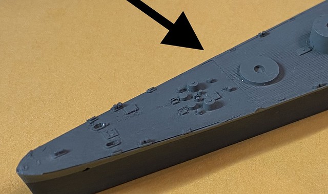
My model is in 1/700, and will be amongst a group of models, so I don't need fine details. I can sort out the radars and electronics from the pictures I have.
I am pained that the USN hadn't updated the Mk 12 radars on the Mk 37; those are quite the challenge to shape from PE parts. :Mad_6: Aging eyes!


Top
 Profile  
Reply with quote  
PostPosted: Wed Oct 12, 2022 7:02 pm 
Offline
User avatar

Joined: Wed Jan 19, 2005 11:19 pm
Posts: 483
Location: San Diego
Pit Road (et seq.) kit for 1/700 USS Miami (CL 89): Has anyone concealed the grotesque seam between the foc's'l deck insert (kit part B2) and the planked main deck (kit part A1, the hull)?

_________________
If humanity wishes to preserve a planet similar to that on which civilization developed and to which life on Earth is adapted, [atmospheric] CO2 will need to be reduced from its current 385 ppm to at most 350 ppm.
Dr James Hansen, NASA, 2008.


Top
 Profile  
Reply with quote  
PostPosted: Wed Oct 12, 2022 11:06 pm 
Offline
User avatar

Joined: Sun Mar 07, 2010 12:01 am
Posts: 1645
Location: Corvallis, Oregon, USA
Michael,

Can you post photos showing what you are talking about?

Phil

_________________
A collision at sea will ruin your entire day. Aristotle


Top
 Profile  
Reply with quote  
PostPosted: Thu Oct 13, 2022 4:19 pm 
Offline
User avatar

Joined: Wed Jan 19, 2005 11:19 pm
Posts: 483
Location: San Diego
One straightforward method is in Mike Ashey's books: fill the seams with putty and sand them. If I damage the wooden deck or molded fittings (e.g., cylindrical vents), then re-scribe the deck and install new fittings. Easier said than done. I plan to repaint this model anyway.

Photos of actual ships show a visible discontinuity athwartships where the deck planks end.

Image

_________________
If humanity wishes to preserve a planet similar to that on which civilization developed and to which life on Earth is adapted, [atmospheric] CO2 will need to be reduced from its current 385 ppm to at most 350 ppm.
Dr James Hansen, NASA, 2008.


Last edited by Michael Potter on Thu Oct 13, 2022 10:26 pm, edited 2 times in total.

Top
 Profile  
Reply with quote  
PostPosted: Thu Oct 13, 2022 5:44 pm 
Offline
User avatar

Joined: Mon Jan 10, 2005 6:00 pm
Posts: 12143
Location: Ottawa, Canada
Mike, your Google Drive does not allow outside linking/views.

_________________
De quoi s'agit-il?


Top
 Profile  
Reply with quote  
PostPosted: Thu Oct 13, 2022 9:12 pm 
Offline
User avatar

Joined: Wed Jan 19, 2005 11:19 pm
Posts: 483
Location: San Diego
I revised the link. OK now?

_________________
If humanity wishes to preserve a planet similar to that on which civilization developed and to which life on Earth is adapted, [atmospheric] CO2 will need to be reduced from its current 385 ppm to at most 350 ppm.
Dr James Hansen, NASA, 2008.


Top
 Profile  
Reply with quote  
PostPosted: Fri Oct 14, 2022 1:33 pm 
Offline
User avatar

Joined: Mon Jan 10, 2005 6:00 pm
Posts: 12143
Location: Ottawa, Canada
Yep, all good now!

_________________
De quoi s'agit-il?


Top
 Profile  
Reply with quote  
PostPosted: Fri Oct 14, 2022 10:28 pm 
Offline
User avatar

Joined: Sun Mar 07, 2010 12:01 am
Posts: 1645
Location: Corvallis, Oregon, USA
The wooden deck ends just forward of the #1 6"/47 turret as shown on the model. The deck was 2 inch thick teak planks 4 inches wide laid directly onto the metal deck plates (with a water seal between the wood and metal). Around the edges of the wood were 2 inch high steel borders 3/8 inch thick that were welded to the steel deck plates.

Short threaded rods were welded to the deck. The deck planks had holes to fit over the rods. The holes were counter sunk 1 inch deep to allow nuts and washers to be threaded onto the rods and tightened. The space around the nuts was filled with white lead and a teak plug was driven into the hole above the nuts. The teak plugs were oriented so the grain matched the grain of the deck planks.

After WWII when six of the Clevelands were converted to missile cruisers the new deck planking was a laminate of 1 inch of teak glued to 1 inch of Douglas fir. I do not know if this laminate planking was used on any of the ships during WWII.

Phil

_________________
A collision at sea will ruin your entire day. Aristotle


Top
 Profile  
Reply with quote  
PostPosted: Sat Oct 15, 2022 8:55 am 
Offline
User avatar

Joined: Mon Nov 18, 2013 3:41 pm
Posts: 2948
Location: Mocksville, NC
Just to illustrate DrPR's description of the teak deck & plug, here is a shot of a small portion of teak decking that was removed from USS NEW JERSEY (BB-62) in the process of mothballing her in 1990. Decking removed was stored for future donation to the ship's crew. At the annual ship's reunion in 1991, those attending the banquet dinner received a plug of the ship's teak deck. I mounted mine on an oak board with a couple other BB tokens -
Attachment:
Deck Plug 1991.jpeg
Deck Plug 1991.jpeg [ 230.87 KiB | Viewed 8350 times ]

This particular piece does have one of the plugs described but is not a full 4" wide section as a small piece of it is missing. However, it does show exactly how the deck looks once installed. Here is a shot of teak being installed on NEW JERSEY a few years ago when the ship's deck renewal project (as a museum ship) was in progress -
Attachment:
BB62 01 Level Teak Decking_1 - Resized.jpg
BB62 01 Level Teak Decking_1 - Resized.jpg [ 240.24 KiB | Viewed 8350 times ]

This photo was taken prior to the decks being sanded smooth.

Hank

_________________
HMS III
Mocksville, NC
BB62 vet 68-69

Builder's yard:
USS STODDARD (DD-566) 66-68 1:144, Various Lg Scale FC Directors
Finished:
USS NEW JERSEY (BB-62) 67-69 1:200
USN Sloop/Ship PEACOCK (1813) 1:48
ROYAL CAROLINE (1748) 1:47
AVS (1768) 1:48


Top
 Profile  
Reply with quote  
PostPosted: Sun Oct 16, 2022 11:22 pm 
Offline
User avatar

Joined: Sun Mar 07, 2010 12:01 am
Posts: 1645
Location: Corvallis, Oregon, USA
Hank,

That new deck looks good. It is the same nibbing and margin bar board pattern as on the Clevelands.

The Cleveland deck planks were 4 inches wide and 2 inches thick (1 inch teak over 1 inch Douglas fir) and the margin boards were 2 1/2 inch thick and a minimum of 6 inches wide at the narrowest parts of the nibs and at least 9 inches wide (or wider if necessary to fit the required space). Where the margin boards abutted deck houses, hatches, scuttles, etc. they were 2 1/2 inch thick against the structures and tapered to 2 inch thick where they joined the deck planks to ensure water didn't stand against the metal parts. All in all it was a fairly complex arrangement.

When they put a new deck on the USS Little Rock CG-4 museum ship a few years back I sent the contractor the original deck blueprints for the CLGs. Instead of wood they used plastic (the same cheap stuff used on decks on houses), and they totally omitted all the nibbing and margin boards around the hatches and superstructure. It looks OK to the ordinary lubber, but it is pretty pathetic to anyone who served on vessels with wooden decks! However, it was cheap, and they didn't have the cash (or contractor) to do it right (they needed a few Chief Bosun's Mates). Funding is the bane of museum ships.

And you answered a question for me. Some navies used 6" wide planks on larger ships and I wondered how wide the Iowa class deck boards were. You show 4 inch planks like on the Clevelands. Was this just on the superstructure decks or on the main deck also?

Phil

_________________
A collision at sea will ruin your entire day. Aristotle


Top
 Profile  
Reply with quote  
PostPosted: Mon Oct 17, 2022 8:46 am 
Offline
User avatar

Joined: Mon Nov 18, 2013 3:41 pm
Posts: 2948
Location: Mocksville, NC
DrPR wrote:
Hank,
And you answered a question for me. Some navies used 6" wide planks on larger ships and I wondered how wide the Iowa class deck boards were. You show 4 inch planks like on the Clevelands. Was this just on the superstructure decks or on the main deck also?
Phil


Phil,
I'm not sure, but I think the main deck is also 4" wide. Here is a photo I took of the foc'sle in 2000 at our 1st reunion aboard ship way before the deck renovation project began, so you can judge for yourself the width of the normal boards -
Attachment:
497179-R1-23 (Large).jpg
497179-R1-23 (Large).jpg [ 176.87 KiB | Viewed 8260 times ]

This decking may have been replaced by now, it wasn't in the best condition at that time. As for your comment re. the LITTLE ROCK's plastic deck replacement, I recall many years ago on NORTH CAROLINA that there were spots where the deck was replaced with tan concrete in place of the rotted teak boards. A very cheap and ugly solution at the time. Her deck has (I believe) since been replaced as photos I've seen of her seem to indicate a nice, clean, teak deck throughout.

_________________
HMS III
Mocksville, NC
BB62 vet 68-69

Builder's yard:
USS STODDARD (DD-566) 66-68 1:144, Various Lg Scale FC Directors
Finished:
USS NEW JERSEY (BB-62) 67-69 1:200
USN Sloop/Ship PEACOCK (1813) 1:48
ROYAL CAROLINE (1748) 1:47
AVS (1768) 1:48


Top
 Profile  
Reply with quote  
PostPosted: Tue Oct 18, 2022 2:05 am 
Offline
User avatar

Joined: Sun Mar 07, 2010 12:01 am
Posts: 1645
Location: Corvallis, Oregon, USA
Hank,

The planks look about the width of a shoe, so probably 4 inches. It would make sense for purchasing and stocking deck materials to have a navy-wide standard width.

Phil

_________________
A collision at sea will ruin your entire day. Aristotle


Top
 Profile  
Reply with quote  
PostPosted: Sat Dec 17, 2022 10:34 pm 
Offline

Joined: Sun Nov 05, 2006 12:44 pm
Posts: 100
Location: Huntington Beach, CA 92646-5446
Richard, can we use this site to discuss your Cleveland? David


Top
 Profile  
Reply with quote  
PostPosted: Mon Dec 19, 2022 2:52 pm 
Offline

Joined: Tue Feb 24, 2009 9:32 am
Posts: 36
Sounds good. I did look at my Cleveland model. It appears to be an easy matter to fabricate the boat crane mast/base from plastic/brass rod/tube. I'll do some measuring tonight. I also found the YMW Cleveland instructions. If you send me your mailing address, I'll copy and send you the specific illustrations--the drawings are very good and detailed. Also, have you looked at the Mk4 mount for the Mk37 director--it is notthe normal mounting--the radar is well extended above the director?


Top
 Profile  
Reply with quote  
PostPosted: Mon Dec 19, 2022 6:32 pm 
Offline

Joined: Sun Nov 05, 2006 12:44 pm
Posts: 100
Location: Huntington Beach, CA 92646-5446
Richard, thank you for guiding me from your YKM 1942 Cleveland through my new VF Cleveland.

I'll build mine in the same Ms 12 Mod as yours, narrowing in on appearance at Operation Torch 08-16NOV1942.

Is yours the YKM-35150 29-page instructions? I have those instructions, but no resin kit.

With no boat farm in the VF kit, it's good to know that the boat crane mast/base are possible from plastic/brass rod/tube. Evergreen plastic rod or Detail Associates brass rod? TMW#5393 pe has the boom latticework. BCM has 26' whaleboats and 36' launches.

Yes, that's a tall Mk4 antenna atop the Mk37 director. Again, Evergreen plastic or Detail Associates brass rods for the framework between them? I'm no good at bending and gluing delicate pe parts, but BCM has the Mk37 Director with Mk4 antenna in compact design that can be cut apart before inserting the tall framework.

I'm grateful for your guidance. More questions to follow.


Top
 Profile  
Reply with quote  
PostPosted: Tue Dec 20, 2022 2:24 pm 
Offline

Joined: Tue Feb 24, 2009 9:32 am
Posts: 36
Base dimensions: 7/32" section of1/4" or 9/32'' dia. plastic rod/tube
Mast dimensions: 3/32" dia. plastic/brass rod 19/32" long centered on top of base or 13/16" in length if placed through the base to the deck. Use the YMW Boat Crane instructions for other details
Also, to get the Mk4 raised mount dimensions enlarge the YMW Instructions Sheet 2 drawing by 160% and measure part #202.
Let me know if you have other questions.


Top
 Profile  
Reply with quote  
Display posts from previous:  Sort by  
Post new topic Reply to topic  [ 474 posts ]  Go to page Previous  1 ... 19, 20, 21, 22, 23, 24  Next

All times are UTC - 6 hours [ DST ]


Who is online

Users browsing this forum: No registered users and 32 guests


You can post new topics in this forum
You can reply to topics in this forum
You cannot edit your posts in this forum
You cannot delete your posts in this forum
You cannot post attachments in this forum

Jump to:  
Powered by phpBB® Forum Software © phpBB Group