The Ship Model Forum

The Ship Modelers Source
It is currently Thu Jun 12, 2025 5:07 am

All times are UTC - 6 hours [ DST ]


Post new topic Reply to topic  [ 2115 posts ]  Go to page Previous  1 ... 61, 62, 63, 64, 65, 66, 67 ... 106  Next
Author Message
PostPosted: Mon Oct 22, 2012 1:41 am 
Offline
User avatar

Joined: Sat Oct 20, 2012 11:01 pm
Posts: 311
Location: Concrete, USA
Howdy! I couldn't find an "introduce yourself" section anywhere on the board, so I figured I would just poke my head in here since I am going to be doing a Fletcher.

Just got myself the Revell 1:144* Fletcher Class model. I've got to say that the parts are really nice and tidy ... no flash to speak of. It will be a pleasant change to work with clean parts. This will just be my 2nd large scale ship I will be building: the 1st being the 1964 issue of the 1:196 Cutty Sark (not finished yet after 6 months) and I have spent most of the time sanding, trimming, filling, and scratch-building replacement parts for pieces that crumbled when I picked them up! LOL But, I did make a promise to myself and my sanity never to do another sailing ship ... hence my switch to a nice, boring, 3-toned gray destroyer.

I plan to mod the kit to fit the design of the 
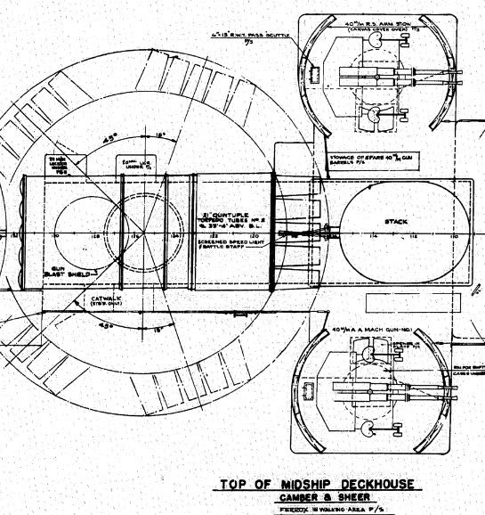
USS Leutze DD481 (Don't ask: it's a long story) using the MS31/16D Dazzle scheme she wore until a Kamikaze plane punched a hole in her on 06APR45 (?) off Okinawa. Some sources say she wore the MS22 in 1945, but I've found no support for that considering that she limped back to California where she never was to see service again. I really think this is the best Dazzle scheme and it should prove to be a challenge to paint. The mod should also be interesting insomuch as the model is designed to portray the early Fletchers with only one 40mm Bofor and no aft tub; whereas the Leutze had the standard 1943 armament of

Primary: 5 x 5-inch/38 cal. in five single mounts
Long-range anti-aircraft: 10 x 40mm Bofors in five twin mounts
Short-range anti-aircraft: 7 x 20mm Oerlikon in single mounts
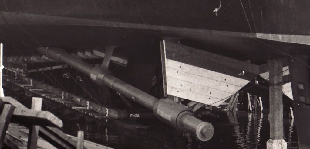
Torpedo Tubes: 10 x 21-inch in two quintuple mounts
ASW: 2 racks for 600-lb. charges; 6 “K”-guns for 300-lb. charges

So, I just have to figure out where to get 4 more twin-mount Bofors and fabricate the following:

4 new Directors (?)(I think thats what they are called)
1 Aft tub
Wing platform for the Forward Stack (and move the searchlights forward)
Convert the Aft Stack wing platform to hold 2 of the Directors
New weapons platforms to each side of the Aft Stack

and ...

figure out where they put the 2 Directors for the Bofors that replaced the 20's on the Bridge Wings!

Did I miss anything??? LOL And I haven't even opened the parts bags yet. :big_grin:

I guess I will have plenty of questions since I don't know diddly about warships. Be seeing you all!

Cody Thecatt (nom de plume)


*Engineers, draftsmen, and Revell use the 1:144 form opposed to the 1/144 form used by many modellers to denote scale ...

_________________
Мощность для рабочих, которые просто пытаются построить простой судна под строгим тиранов! - В. И. Ленин

Hello from Elk & Steelhead country and Cody the Incorrigible Cat

Image


Top
 Profile  
Reply with quote  
PostPosted: Mon Oct 22, 2012 6:17 am 
Offline

Joined: Tue Nov 03, 2009 9:28 pm
Posts: 2126
Location: Egg Harbor Twp, NJ
:welcome:

Rick Davis, et al., will be along any time now but to get you started, http://www.navsource.org/archives/05/481.htm
http://www.fold3.com/s.php#s_given_name ... &t=750,493

It strikes me that this thread almost needs an index, but you may find the search feature at the top of the page to be useful. You can restrict the search to this thread and search Revell or Leutze to locate prior postings about the kit or ship.


Top
 Profile  
Reply with quote  
PostPosted: Mon Oct 22, 2012 8:58 am 
Offline

Joined: Thu May 29, 2008 8:02 pm
Posts: 3841
Cody,

Good luck. The Revell 1/144 scale FLETCHER kit isn't one of my favorites, a lot of "hidden" issues. Biggest headaches are missing items for the bridge wings and other items that are common on smaller scales of the FLETCHER kit and SHOULD be there. Many people replace the 5-in mounts because of the multi-part gun mount parts. There are a couple of after-market resin firms that make the twin 40-mm mounts in this scale, WEM comes to mind as one. Fortunately you have selected an Earlier "Round-bridge" FLETCHER, hence you won't need to convert to a Square-bridge.

Check out the "Works in Progress" section for several Revell 1/144 scale FLETCHER builds. If you go through several pages of that sub-forum, there will be several builds. Not sure if any have been finished.

More later, I have to go.

Rick


Top
 Profile  
Reply with quote  
PostPosted: Mon Oct 22, 2012 12:44 pm 
Offline

Joined: Sun Nov 14, 2010 4:54 pm
Posts: 330
For various reasons, and despite getting some really great information regarding the Mullany, I too am going to build the Leutze in 48th scale, mainly because of the camouflage scheme which is very 'dazzling'.

Rick has been very helpful to me regarding the Leutze.

Several things that I have been able to note about the Leutze that are 'unique':-

the location of the Mk51 directors on top of the bridge are further back than on almost any other Fletcher with no half moon bridge roof extensions forward.

the location of the waist 20mms is much further aft than on any other Fletcher, except the other catapult Fletchers, all of whom then moved them forward when they were converted from catapult ships and then upgraded to gun Fletchers. As Leutze was a much delayed catapult Fletcher that never received her catapult, for some unknown reason the 20mm's stayed way back there.

as a result, the six K-guns are also much further aft than normal and are, if you look at photos, actually mounted much closer together than on other Fletchers, so close in fact that she could not accomodate double reload racks.

In the navsource link above, have a look at the commisioning ceremony photo and you will see the very aft 20mm tub and K-guns. Also you will see that Leutze was still in MS31/16D on the 6th of April, 1945.

Hope this helps.
Sandy


Top
 Profile  
Reply with quote  
PostPosted: Mon Oct 22, 2012 2:09 pm 
Offline
User avatar

Joined: Sat Oct 20, 2012 11:01 pm
Posts: 311
Location: Concrete, USA
thanks Sandy!

I had completely missed the placement of the midship 20's and the K-guns. I see now that the 20's are centered in line with the 3rd 5" gun and the K's are centered with the 4th 5".

If I move the 20's mounts back and "hop" the first K's back to the third position aft, then that will probably be good enough for me LOL.

I usually spend about a month gathering data and pictures before I even start a build. Sadly there is a lack of good pics of the Leutze and it has a very unique deck plan due to it being built in '41-'42 for the catapult fitting and just 1 40mm gun and then being refitted for the 10 40mm's before being deployed in '44. So, that probably makes her a one-of-a-kind in the class. Need more pics! LOL

I'm not sure what you are referring to with the MK51 directors, but I sure I will learn the jargon quickly enough to catch on.

Thanks again.

_________________
Мощность для рабочих, которые просто пытаются построить простой судна под строгим тиранов! - В. И. Ленин

Hello from Elk & Steelhead country and Cody the Incorrigible Cat

Image


Top
 Profile  
Reply with quote  
PostPosted: Mon Oct 22, 2012 2:48 pm 
Offline

Joined: Tue Nov 03, 2009 9:28 pm
Posts: 2126
Location: Egg Harbor Twp, NJ
The Mk 51 Directors are the gun fire directors for the 40mm guns. The Pointer and Trainer on the gun mount did not aim the gun unless the Mk 51 director was knocked out.

Here is an example of one. http://www.modelwarships.com/reviews/mi ... ector.html

A controlling director was situated so as to me able to be pointed wherever the gun mount could point. So for the 40mm mounts up toward the bridge, there would have to be one on each side, matched to the gun mount on that side. When you get to the point of mounting the guns and directors on your model, remember that the gun mount and director were linked so that whichever way the director is facing, the corresponding gun mount should be facing.


Top
 Profile  
Reply with quote  
PostPosted: Sat Oct 27, 2012 10:13 am 
Offline

Joined: Sun Nov 14, 2010 4:54 pm
Posts: 330
Here is a photo of Leutze that shows the waist 20mm and depth charge position quite well:-

Image

Here is a photo of Halford which was the Puget Sound Navy Yard Fletcher that did get the catapult and you can see the location of the K-gun racks and waist 20mm's as well:-

Image

The curious thing is that, with the long delay in completing the Leutze, they did not move the 20mms forward and hence allow the K-gun sto move forward as well.

Hope this helps.

All the best
Sandy


Last edited by sandy on Sat Oct 27, 2012 4:17 pm, edited 1 time in total.

Top
 Profile  
Reply with quote  
PostPosted: Sat Oct 27, 2012 11:48 am 
Offline
User avatar

Joined: Sat Jan 21, 2012 5:43 pm
Posts: 371
codythecatt wrote:
thanks Sandy!
I usually spend about a month gathering data and pictures before I even start a build. Sadly there is a lack of good pics of the Leutze and it has a very unique deck plan due to it being built in '41-'42 for the catapult fitting and just 1 40mm gun and then being refitted for the 10 40mm's before being deployed in '44. So, that probably makes her a one-of-a-kind in the class. Need more pics! LOL

I'm not sure what you are referring to with the MK51 directors, but I sure I will learn the jargon quickly enough to catch on.

Thanks again.


Hi Cody,
Check out this link for Sprue Brothers http://store.spruebrothers.com/product_p/gfm14402.htm.
This set is made by G-Factor and it contains: one twin 40mm Bofors gun, one MK-51 gun director, one single 20mm Oerlikon and one ready service ammo locker in 1/144 scale. They're not cheap though, 14.49 perset and you will need five sets. :heh: :heh: Sprue Brothers also has other after market parts for the Revell Fletcher and they sell Life Color Paints by the bottle that are always in stock so you don't have to buy both sets to have the WWII USN colors. WEM paints are considered the best, but most of the time they're out of stock. I wish you the best on your build. :thumbs_up_1: :big_grin:

Roger DD-473/DD-555 :wave_1:


Top
 Profile  
Reply with quote  
PostPosted: Sat Oct 27, 2012 1:16 pm 
Offline
User avatar

Joined: Sat Oct 20, 2012 11:01 pm
Posts: 311
Location: Concrete, USA
thanks you guys!

I'm right in the middle of moving to a new home now (picking up the moving van in 2 hours), but when I get settled a bit I will probably start a build log for this beastie

:thumbs_up_1:

_________________
Мощность для рабочих, которые просто пытаются построить простой судна под строгим тиранов! - В. И. Ленин

Hello from Elk & Steelhead country and Cody the Incorrigible Cat

Image


Top
 Profile  
Reply with quote  
PostPosted: Wed Nov 07, 2012 8:22 pm 
Offline

Joined: Sun Mar 01, 2009 1:28 am
Posts: 27
Rick E Davis wrote:
An option for you is to order a DVD of the Bath Iron Works (BIW) FLETCHER Class Engineering Drawings from the Destroyer History Organization ... http://destroyerhistory.org/destroyers/store/ ... for $30 you get plans for the four different variations of the FLETCHER class that BIW built.

1) Original group with the enclosed bridge (Round-bridge) with a single quad 1.1-in mount ... DD449-451
2) Enclosed bridge units with two twin 40-mm mounts, one on the fantail ... DD467-469 and 507-517
3) Initial revised open bridge units (Square-bridge) with three twin 40-mm mounts ... DD629-631 and 642-644 (really didn't last long on DD-644)
4) Ultimate revised open bridge units with altered bridge with five twin 40-mm mounts ... DD650-653 and 688-691 (the six units in the previous group above were updated to this standard)

These plans are the ones that BIW used to build the destroyers and much applies to all FLETCHERS. Any variations generally can be derived from the available photos or other drawings. The plans were scanned from the original drawings on microfilm at the National Archives by the founder of Destroyer History Org., Dave McComb at great expense on his part and at $30 it is a GREAT bargain. The plans take getting use to in finding what you need. Best to print out the index (on the DVD) and go through ALL of the 100's of drawings and note as you go what you want to reference later.

It is well worth the cost for the DVD. If you are serious about scratch-building it will be invaluable. Once you have narrowed down to a specific ship, I may have some additional drawing info available.


Just received the DVD -- amazing. Since the USS Van Valkenburgh (DD 659) was built by Gulf Shipbuilding, am I correct in assuming (I hate that word in research) that the Bath Iron Works DD 650 drawings would still be applicable?

PeeJay


Top
 Profile  
Reply with quote  
PostPosted: Thu Nov 08, 2012 12:30 am 
Offline

Joined: Thu May 29, 2008 8:02 pm
Posts: 3841
To be certain, check photos for the differences. The DD-650-653 & 688-691 drawings on the BIW DVD are the ones you will want.

For starters, check out Folder 5541-1, files 50, 51, & 52 for profile and files 403-411 for the various deck views. The general arrangements for the waist twin 40-mm mounts and waist 20-mm guns bulwarks look to be the same. That is one of the issues for modeling the Square-bridge FLETCHERS.


Example the bridge area:
Image

Example the midships area:
Image


Remember that the frames are 21-in apart.

Print out the Index and take time to wander through the drawings, making notes on the index for features you may want to use. Have fun. :smallsmile:


Top
 Profile  
Reply with quote  
PostPosted: Wed Nov 14, 2012 3:31 pm 
Offline
User avatar

Joined: Sat Oct 20, 2012 11:01 pm
Posts: 311
Location: Concrete, USA
snaphappy321 wrote:
Hi Cody,
Check out this link for Sprue Brothers ... I wish you the best on your build. :thumbs_up_1: :big_grin:
Roger DD-473/DD-555 :wave_1:


thanks Rodger! Somehow I had missed your post. (I was in the middle of moving). Yep, they are pretty spendy but maybe I can get them one at a time as my budget allows. :smallsmile: But they are really sharp looking! Made of white bronze? Is that hard to work with?

Oh, but back to reason for my post. Does anybody with blueprints know what material the propeller shafts are made of on the Fletchers? I've seen models with it painted with "bottom red", grey, or as bronze ... from my experience on various boats the shaft is not sheathed, never painted, is usually a disimiliar metal, and protected by zincs. My guess would be of the same material as the propellers (which from my research would have been a bronze alloy and not a shiny brass screw?). But i have no clue how the navy did it. Hopefully somebody has a definative answer for me since installing the propellers and shafts is one of the first steps in the construction.

_________________
Мощность для рабочих, которые просто пытаются построить простой судна под строгим тиранов! - В. И. Ленин

Hello from Elk & Steelhead country and Cody the Incorrigible Cat

Image


Top
 Profile  
Reply with quote  
PostPosted: Thu Nov 15, 2012 11:53 pm 
Offline
User avatar

Joined: Sat Oct 20, 2012 11:01 pm
Posts: 311
Location: Concrete, USA
bumpity, bump.

Inquiring minds need to know ... since I'm headed down river tomorrow to the 'big' city and the only hobby shop within 60 miles. :wave_1:

_________________
Мощность для рабочих, которые просто пытаются построить простой судна под строгим тиранов! - В. И. Ленин

Hello from Elk & Steelhead country and Cody the Incorrigible Cat

Image


Top
 Profile  
Reply with quote  
PostPosted: Fri Nov 16, 2012 1:24 am 
Offline

Joined: Tue Nov 03, 2009 9:28 pm
Posts: 2126
Location: Egg Harbor Twp, NJ
To the best of my knowledge, the shafts were turned, meaning lathed, steel and the props were bronze.

Somewhere in the forum there was a discussion about coatings and it was concluded that the shafts were painted.


Top
 Profile  
Reply with quote  
PostPosted: Fri Nov 16, 2012 6:12 pm 
Offline
User avatar

Joined: Wed Jun 30, 2010 5:19 pm
Posts: 11
Location: Bristol, England
** Post removed due to stupidity of poster. Apologies for the distraction! **

_________________
"Train? What train?" - G.J. Churchward


Top
 Profile  
Reply with quote  
PostPosted: Fri Nov 16, 2012 6:50 pm 
Offline

Joined: Tue Nov 03, 2009 9:28 pm
Posts: 2126
Location: Egg Harbor Twp, NJ
One source in the States is Floating Drydock

The plans are not in 1/72 but, generally, in 1/96 but sometimes available in other scales.

The Master Plan list has a listing of all available plans from this source. They are categorized by who drew them. For example, Bu indicates US Navy Bureau of Ships.
Hull lines are definitely available.

http://floatingdrydock.com/MasterPlan.htm


Top
 Profile  
Reply with quote  
PostPosted: Sat Nov 17, 2012 8:06 pm 
Offline
User avatar

Joined: Sat Oct 20, 2012 11:01 pm
Posts: 311
Location: Concrete, USA
Russ2146 wrote:
To the best of my knowledge, the shafts were turned, meaning lathed, steel and the props were bronze.
Somewhere in the forum there was a discussion about coatings and it was concluded that the shafts were painted.


Russ,

I am going to try to chase up some "expert" references on the matter. I will post any results I get. Even though I'm not a 'professional' modeller by any stretch of the imagination I am a chronic stickler for details. And previously I have been 'led down the garden path' by a couple of folks who, as it turned out, really didn't have a clue what they were talking about ... but they sure could spout 'facts' about the Cutty Sark. LOL :smallsmile:

For now my build will be put on hold for this particular part ... bummer :smallsmile:

_________________
Мощность для рабочих, которые просто пытаются построить простой судна под строгим тиранов! - В. И. Ленин

Hello from Elk & Steelhead country and Cody the Incorrigible Cat

Image


Top
 Profile  
Reply with quote  
PostPosted: Sat Nov 17, 2012 10:05 pm 
Offline

Joined: Tue Nov 03, 2009 9:28 pm
Posts: 2126
Location: Egg Harbor Twp, NJ
There is a standard for the repair of bronze propellers but not for other metals
NAVY DOD-STD-2185: REQUIREMENTS FOR REPAIR AND STRAIGHTENING OF BRONZE NAVAL SHIP PROPELLERS

Here's a picture of a Navy diver checking a propeller.
http://www.flickr.com/photos/usnavy/5828734308/

Here's a photo of one of the USS South Dakota's props
Attachment:
Prop of South Dakota.jpg
Prop of South Dakota.jpg [ 12.78 KiB | Viewed 1967 times ]


here's a nice new one with shaft
Attachment:
th.jpg
th.jpg [ 19.19 KiB | Viewed 1967 times ]


This explains a little about propeller shafts
http://www.brighthubengineering.com/mar ... tern-tube/


Purpose and Operation of the Propeller Drive Shaft

The propeller shaft is bolted to the main engine flywheel, passing through the thrust block then along the shaft tunnel. Here it is supported by the shaft bearings before passing through the stern tube to drive the ship's propeller.

The shaft is manufactured from forged steel, complete with coupling flanges. It is machined leaving a larger diameter at the location of the shaft bearings; this section has to have a fine finish to run within the white metal bearing. http://www.brighthubengineering.com/mar ... tern-tube/

See Also

http://firecontrolman.tpub.com/14104/css/14104_119.htm


Top
 Profile  
Reply with quote  
PostPosted: Sun Nov 18, 2012 12:40 am 
Offline

Joined: Thu May 29, 2008 8:02 pm
Posts: 3841
Here are some photos ... during construction and after some operational use.

I tried to locate drawings/specs for the shafts on the BIW FLETCHER Class Engineering Drawings DVD, but had no luck. The shafts "may" have been government furnished items that the USN contracted with a supplier direct. The shafts were made from steel and I'm pretty sure that the "exposed" parts of the shafts were always painted just like the hull. The sections inside the strut bearings were left as polished metal. The props were bronze. I know of one case where one builder was authorized to use solid shafting on some units to "speed" construction, but the specs called for hollow shafts.

Image

Image


Top
 Profile  
Reply with quote  
PostPosted: Sun Nov 18, 2012 7:38 am 
Offline
User avatar

Joined: Sat Oct 20, 2012 11:01 pm
Posts: 311
Location: Concrete, USA
Thanks Rick and Russ. I appreciate your help. If the shafts were indeed made of steel they would obviously have to be painted ...

I have one other source I am checking with also.

Thanks again.

_________________
Мощность для рабочих, которые просто пытаются построить простой судна под строгим тиранов! - В. И. Ленин

Hello from Elk & Steelhead country and Cody the Incorrigible Cat

Image


Top
 Profile  
Reply with quote  
Display posts from previous:  Sort by  
Post new topic Reply to topic  [ 2115 posts ]  Go to page Previous  1 ... 61, 62, 63, 64, 65, 66, 67 ... 106  Next

All times are UTC - 6 hours [ DST ]


Who is online

Users browsing this forum: No registered users and 2 guests


You can post new topics in this forum
You can reply to topics in this forum
You cannot edit your posts in this forum
You cannot delete your posts in this forum
You cannot post attachments in this forum

Jump to:  
Powered by phpBB® Forum Software © phpBB Group