The Ship Model Forum

The Ship Modelers Source
It is currently Wed Jun 04, 2025 9:25 am

All times are UTC - 6 hours [ DST ]


Post new topic Reply to topic  [ 2115 posts ]  Go to page Previous  1 ... 77, 78, 79, 80, 81, 82, 83 ... 106  Next
Author Message
PostPosted: Tue Jun 23, 2015 11:59 am 
Offline
User avatar

Joined: Sat Apr 29, 2006 7:36 am
Posts: 681
Location: Vigo, Spain
Hi there Mr. Davis and all,

I am very interested in the Fletcher-class destroyers as I am currently building Jorge Juan, ex-USS McGowan, one of the Fletcher´s on lease to the Spanish Navy. You can see it at (the construction details starting from post nr.3 on):

http://www.u-modelismo.com/foromodelism ... pic=1681.0

As the scale is 1/144, which allows almost anything, I am interested in detailing it as much as possible. Searching for some info about the lower hull, I found your post of Aug 30, 2014, the one including this pics set:

Rick E Davis wrote:
Image


I have to say that only very seldom I have seen such an interesting, complete and informative post. You have saved me and the rest of the folks here months of web surfing.
If it is possible, would you be kind enough as to upload a scan of the only gap in these pictures, corresponding to the space of frames 146-166?
I would be way more than thankful for this enormous favor.

TIA, and best regards from this side,

Willie.

_________________
Amen dico tibi, hodie mecum eris in paradiso (Lk 23,43).


Top
 Profile  
Reply with quote  
PostPosted: Tue Jun 23, 2015 7:20 pm 
Offline

Joined: Thu May 29, 2008 8:02 pm
Posts: 3840
Willie,

Well I would post the "missing" piece of USS HAZELWOOD's Docking Plan, but I don't have it. At the US National Archives they have many of the "Booklets of General Plans" (BGPs) for many of the 175 FLETCHER class destroyers, but not for ALL of them. A few of the BGPs drawings are actually the original drawings that the blueprint BGPs were made from. Those are really nice for having scanned by a large-format scanner. Sometimes they have other drawings besides BGPs, but not many. I methodically went through every folder and paper drawings that NARA has for FLETCHERS and there were gaps. In the case of HAZELWOOD I was HOPING to get drawings/plans for the Helicopter Deck ... DASH ... configuration. But they didn't have those plans. They did have her Docking Plan from the 1950s. For all of the BGPs of FLETCHERS I took digital camera views of various sections, normally multiple views of each sheet, many of these plans repeated so I didn't take ALL of the same images of ever view and every ship. For some drawings I had large format scans made. But, because most of the BGPs are pasted together "booklets", they can't easily be scanned. Besides, with over 100 plans, I can't afford to have ALL of them scanned anyway.

Anyway, back to HAZELWOOD's Docking Plan. I took digital views of each section that had info on openings or things like sonar locations. I skipped the Frame 146 to 166 area because not much was there. However, without making a trip to just take a photo of that area of the plan. I'm going to post an image from the ONLY OTHER Docking Plan I came across at NARA for FLETCHERS. I came across a docking plan for USS ALBERT W. GRANT (DD-649) as she was configured at the end of WWII. For me this was really nice, I had a WWII and 1950s versions.

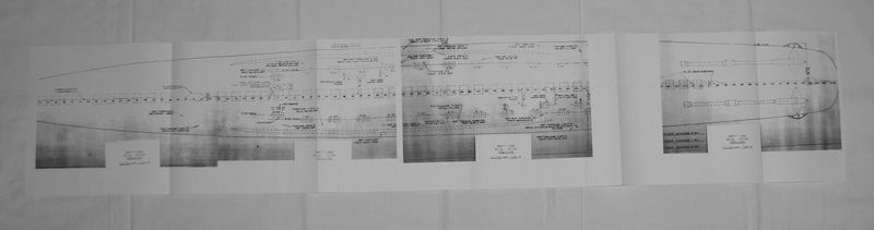
Anyway, I have uploaded an overall view of A. W. GRANT's Docking Plan and I hope that answers your question. I used HAZELWOOD's Docking Plan before, because it is "less" cluttered as you will see. GRANT's Docking Plan included a profile view of the hull. I hope this answers your questions.

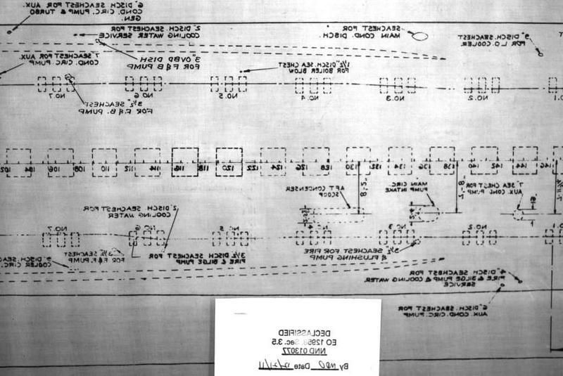
As you can see, there are no discharges, scoops, or other devices between Frames 146 to 166.

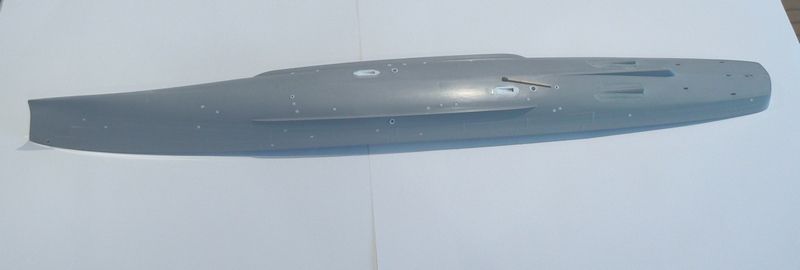
First image is an overview of most of the hull.

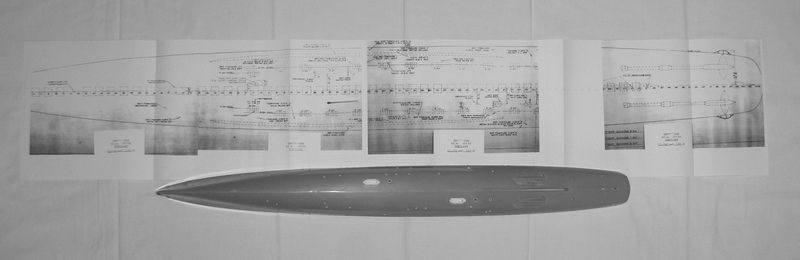
The second view shows the aft area you asked about ago view giving you an overlapped view of the sections forward of that area.

The third image shows the forward area from the end of WWII Retractable Dome Sonar was located.

Image


Image


Image


Top
 Profile  
Reply with quote  
PostPosted: Thu Jun 25, 2015 7:02 am 
Offline
User avatar

Joined: Sat Apr 29, 2006 7:36 am
Posts: 681
Location: Vigo, Spain
Hi there Mr. Davis,

Once more a one-in-million post. Thanks a lot for it, for this will make me save countless hours of research.
After crossing these plans with some drydock pictures in my files, I have only one more doubt: The side view is as clear as can be, but regarding the keel view, I understand that the plans are showing the bottom details as if "sitting" on the dry dock under the ship, and looking upwards, am I right ?
I mean, that the broken lines --of the bilge keels, for example-- are not showing the details as if standing on the main deck, and looking downwards through it.

Thanks very m,uch again for your precious help, and warmest regards from this side of the pool,

Willie.

_________________
Amen dico tibi, hodie mecum eris in paradiso (Lk 23,43).


Top
 Profile  
Reply with quote  
PostPosted: Thu Jun 25, 2015 10:52 am 
Offline

Joined: Thu May 29, 2008 8:02 pm
Posts: 3840
These two sets of drawings are done differently, but orientated the same ... looking down through the ship. The easiest way to know and get the layout right is to look for the location of the Condenser Scoops ... the Forward one was on the portside (at Frame 91) and the Aft one was on the starboard side (at Frame 128). Those never changed. Figure out everything else from that. Looking at these two drawings the Condenser Scoops, etc are laid out the same. Only the "Vertical Echo Sounding Projectors" are on different sides of the keel. The "Vertical Echo Sounding Projector" (depth-finder) was on the STARBOARD side of the keel on FLETCHER's at roughly Frame 53 during WWII. Hence, ALBERT W. GRANT drawing is correct ... for WWII.

When the FLETCHERs were recommissioned for the Korean War, the SQS-10 sonar was installed in the Frame 25 location, the same location that the late-WWII retractable Sonar was located. During the mid-1950s when the USN installed the SQS-29/30/31/32 family of Sonars (which one installed depended on the ship), they relocated it to Frame 53. This forced relocating the Echo Sounding Projector. So for mid-1950's units still in commission (1957 and after) HAZELWOOD's plan is correct.

To make matters worse, on some FLETCHERs around about 1959-60 the sonar was relocated BACK to frame 25. But not ALL FLETCHERs in service in the 1960s had this done. Plus, depending on the SQS-29/30/31/32 sonar installed, the sonar domes were different sizes. Fun isn't it. :smallsmile:


Attachments:
DD478FwdCondenserScoop.jpg
DD478FwdCondenserScoop.jpg [ 170.55 KiB | Viewed 7672 times ]
DD478AftCondenserScoop.jpg
DD478AftCondenserScoop.jpg [ 182.28 KiB | Viewed 7672 times ]
DD478EchoSounding.jpg
DD478EchoSounding.jpg [ 191.47 KiB | Viewed 7672 times ]
Top
 Profile  
Reply with quote  
PostPosted: Fri Jun 26, 2015 4:35 am 
Offline
User avatar

Joined: Sat Apr 29, 2006 7:36 am
Posts: 681
Location: Vigo, Spain
Hi there Mr. Davis and David P.,

Thanks for your orientation. Everything is now as clear as can be.

Rick E Davis wrote:
These two sets of drawings are done differently, but orientated the same ... looking down through the ship. The easiest way to know and get the layout right is to look for the location of the Condenser Scoops ... the Forward one was on the portside (at Frame 91) and the Aft one was on the starboard side (at Frame 128). Those never changed.


This means that I have to take the scans of Hazelwood as they are, reverse them horizontally, and done. Easiest thing ever !!!!!!!
My ship Jorge Juan was sister ship of Hazelwood, so I will simply have to copy the scoops pattern.
The best thing of these Internet forums is to have the company of experts and their advice.

Again, thanks a million, and best regards from this side of the world,

Willie.

_________________
Amen dico tibi, hodie mecum eris in paradiso (Lk 23,43).


Top
 Profile  
Reply with quote  
PostPosted: Fri Jul 17, 2015 3:47 am 
Offline
User avatar

Joined: Sat Apr 29, 2006 7:36 am
Posts: 681
Location: Vigo, Spain
Hi there Mr. David, DavidP and all,

The thing is done. I have reversed the pics using a photography program, to achieve this :

Image

And then I made a plan gluing the sections together, with the gap between frames 146-166 :

Image

Then I simply found out the exact position of ech sea chest, intake and scoop :

Image

The condenser scoops :

Image

Image

And all the rest of the sea chests, using Evergreen tube in four different calibers :

Image

Image

Image

Image

The contrast between white tubing and grey hull is very sharp, but once painted it will look way better.

Image

Image

I have to build the sonar dome and the echo sound projector fairwater yet, but with what has been done I can already close the hull and start the deck structures.
I hope you like my solutions so far.

Thanks again for your precious help, and warmest regards from this side,
Willie.

_________________
Amen dico tibi, hodie mecum eris in paradiso (Lk 23,43).


Top
 Profile  
Reply with quote  
PostPosted: Fri Jul 17, 2015 11:32 am 
Offline
Model Monkey
Model Monkey

Joined: Sat Aug 20, 2005 9:27 pm
Posts: 4041
Location: USA
Brilliant!

_________________
Have fun, Monkey around.™

-Steve L.

Complete catalog: - https://www.model-monkey.com/
Follow Model Monkey® on Facebook: - https://www.facebook.com/modelmonkeybookandhobby


Top
 Profile  
Reply with quote  
PostPosted: Sun Jul 26, 2015 11:12 pm 
Offline
User avatar

Joined: Thu Sep 12, 2013 9:33 am
Posts: 138
Great solutions for the hull--never seen anyone do a full hull detail before so it is really nice to see it done in 3D. Very nice. :cool_1:

_________________
~Harq


Top
 Profile  
Reply with quote  
 Post subject: DD 502 USS Sigsbee
PostPosted: Fri Jul 31, 2015 5:23 pm 
Offline

Joined: Thu Dec 25, 2008 8:15 am
Posts: 46
Rick, I've seen you comment that Sigsbee holds special interest for you. Perhaps you could answer a question for me. I am converting a Tamiya 1/350 Fletcher to Sigsbee, in her mid-war, ten 40mm barrel configuration, as appears in the photo on page 1 of your "Round Bridge Fletcher", Warship Pictorial 42. My question is whether she had floater net baskets mounted after the conversion like most of the Fletchers about that time period? These locations were typically a curved version of the floater net baskets behind the searchlight platform on the forward stack, and a straight type floater net baskets behind the gun director platform on the aft stack. I see them on the other boats, but cannot see them in the the few photos of Sigsbee from this period. In fact, I don't see any mounted anywhere, in front of the 52 gun platform, on the sides of the deckhouses, etc. Most of the published shots of Sigsbee are from earlier or later time frames, but as I say, the couple I have found on line, do not show the floater net baskets, which I found pretty odd.
Thanks,

Rick
throck3


Top
 Profile  
Reply with quote  
PostPosted: Fri Jul 31, 2015 10:22 pm 
Offline

Joined: Thu May 29, 2008 8:02 pm
Posts: 3840
Rick,

An interesting question that I never really checked on before. But, it kind of depends on WHEN you are modeling SIGSBEE in her ten 40-mm configuration. After her late 1944 (December) refit she had the "standard" floater net basket arrangements on the stack platforms and at least one pair aft on the 01 deck. But, after her January 1944 upgrade to the ten 40-mm configuration with two twin 40-mm mounts installed before her bridge at Pearl Harbor, she doesn't appear to have many if any baskets. Certainly none high up around her stack platforms until the December 1944 overhaul.

How then I'm pretty sure she HAD floater nets, just not in baskets. Some background. Early in the war, they didn't install floater baskets on destroyers, floater nets were tied in bundles along the main deck edge. The thought was that if a ship was sinking then these would float off easier. Some of the earlier FLETCHERS still followed this practice as they were being completed. Then on some early units like FLETCHER and her immediate sisters, they installed wood slat baskets up high. Some in the USN thought those "high up" baskets were mounted too high to be of ANY use in a sinking. So during when SIGSBEE and her Federal-built sisters (DD-498 to 502), the baskets were deleted. But, it was found in action that the nets along the deck positions would get loosen and was causing more of a crew hazard than a life saver. Floater Net Baskets mounted up at least one deck higher was considered the solution by early 1943. Most of the early FLETCHERS got floater net baskets installed piecemeal during overhauls or during tender availabilities.

From the "as completed ... fitting out" period at the New York Navy Yard, SIGBEE had extra life-rafts installed (there were at least five stacked on her fantail before she was upgraded to the six 40-mm configuration) for a total of about 13-14 life rafts. That's A LOT for a destroyer. After her upgrade to the six 40-mm configuration she had eight-ten rafts. So, I have to wonder if SIGSBEE's CO did NOT much like floater nets? After her January 1944 PHNY refit to the ten 40-mm configuration, it looks like she had eight life rafts.

I say "standard" floater net basket arrangements with tongue in cheek. Because there was A LOT of variation as to where they were installed and how. I have seen nice "builder-installed" locations seen on ALL sisters built at that same yard, at some point get one or two pairs of baskets MOVED to different locations.

So, depending on when you wish to model SIGSBEE, before or after her December 1944 overhaul when she had RCM and floater baskets installed, then that will decide if you need the baskets. Bundles would be "generally" installed along the main deck edge or along the next higher deck edge, but I'm sorry that I can NOT pinpoint them. The photos I have available aren't clear enough to show what is going along the the entire railing. Crews stowed all kinds of stuff along the railings (and elsewhere) that can be defined as being considered "standard" practice. I see bundles of floater nets, "I think" ... I'm not positive, in four places; under the forward twin 40-mm mount just forward of the life raft there, one aft of the breakwater before the waist twin 40-mm location, one (maybe?) aft of the waist twin 40-mm location, and one just aft of the K-Guns.

If you go with modeling her as she appeared when she was hit by a Kamikaze, then there are a lot of images available. Also, there is a set of BGP plans for SIGSBEE after her December 1944 refit here ...

... ww.hnsa.org/wp-content/uploads/2014/08/dd502.pdf ....

Attached is about the only GOOD view I have of a floater net bundle and it is mounted on the 01 deck edge above the forward life raft. Also, a view of USS NICHOLAS showing her combo of baskets and deck edge bundle stowage of floater nets.


Attachments:
DD498xFloaterNetBundle-22Aug44.jpg
DD498xFloaterNetBundle-22Aug44.jpg [ 163.72 KiB | Viewed 7332 times ]
DD449xFloaterNetStowage-Jul43.jpg
DD449xFloaterNetStowage-Jul43.jpg [ 136.93 KiB | Viewed 7332 times ]
Top
 Profile  
Reply with quote  
PostPosted: Sat Aug 01, 2015 6:33 am 
Offline

Joined: Thu Dec 25, 2008 8:15 am
Posts: 46
Once again, Wow!. Thanks, Rick! The info on floater net bundles is new to me. I had never given that a thought, and thanks for the photos. Arbitrarily, I had chosen the June 1944 period for my build because it matched the nice, clear photo you use on page 1 of your Warship Pictorial, Round Bridge Fletcher. This information helps tremendously. Now that I know what I am seeing, I think I can see the bundles just above and aft of the forward life raft, and behind the waist 40mm position on main deck level. I also, when putting the glass to it, think I am seeing an actual floater net basket mounted on the bulkhead at 01 level between 51 and 52 mounts. There are some other white, box shaped stowage thrown on top of it, but it does appear to be a net basket to me.

Once again, you have helped tremendously. I plan on doing this mid-war conversion of a round bridge, and then an early, as built version of a Fletcher with the elevated Chicago Piano mount, probably Chevalier in her early Atlantic duties appearance, and then a late war anti-kamakazi fit. I retired over the holidays, so have some time to devote to this (if I don't burn myself out!).

I do have a question I have been meaning to ask you. In the famous 15 Aug 43 photos of of O'Bannon, Chevalier, and Taylor, steaming in column near Guadalcanal, I notice the gun director radars as well as the main radars are of a lighter color than the 5N of the rest of the boats. Why is that? Were they left natural metal or painted a different color? Later in the war, the radars appear to be the same color as the rest of the upper structures.


Thanks,
Rick T

As a post script, just imagine the response a quality round bridge and square bridge Fletcher series in 350 scale along the lines of the Dragon Gleaves class would get. The Fletcher seems to be everybody's favorite destroyer class of the period. Of course, I'm preaching to the choir and beating that dead horse all at the same time. RT


Top
 Profile  
Reply with quote  
PostPosted: Sat Aug 01, 2015 10:50 am 
Offline

Joined: Thu May 29, 2008 8:02 pm
Posts: 3840
The installation/use of floater nets with and without baskets onboard ships is one area that is next to impossible to catalog. As I said, I have noticed that the CO/crews seemed to have latitude to move them if they had a "better idea". The space on either side of the elevated twin 40-mm between 53 and 54 mounts was another place where floater nets were stowed. The nets and many other items commonly stowed is something that individual modelers have to study photos of their subject if they want to go into that much detail on their final model.

The high reflectance seen on early radar antennas, particularly the Mk 4 (also known as FD) radar on the Mk 37 director was a result of the coatings used. Straight camo paint couldn't be used because it interfered with the electrical properties of the antenna. A varnish coating was used early on but came up with the results seen in photos. A special "paint/varnish" was developed and used starting on units delivered in about mid-1943. The only way I even knew that was because I came across a memo in official records about it and then noticed in Departure Reports a line item about applying this coating on destroyer antennas that didn't yet have it.


Top
 Profile  
Reply with quote  
 Post subject: Rick, Ms. 18?
PostPosted: Sat Aug 22, 2015 1:52 am 
Offline

Joined: Sun Nov 05, 2006 12:44 pm
Posts: 107
Location: Huntington Beach, CA 92646-5446
Hi, Rick. In your Round Bridge Fletcher book, page 30, you refer to Strong wearing Ms. 18; however, Ms. 18 is not listed in Snyder & Short's WWII USN Camouflage. What are the two vertical colors in Ms. 18, and are they simply applied darker shade on the hull and lighter shade on everything above? Thanks


Top
 Profile  
Reply with quote  
PostPosted: Sat Aug 22, 2015 9:47 am 
Offline

Joined: Thu May 29, 2008 8:02 pm
Posts: 3840
When the "new" camo schemes came out in about August 1942, Ms 18 was one of them along with Ms 21 and Ms 22. I don't know why Ms 18 was used on some ships or its intended purpose, but particularly in August 1942 it was used on a fair number of units completing. And yes it doesn't get mentioned in many of the Camo references. It generally faded away after the Atlantic Fleet choose Ms 22 as their standard and the Pacific Fleet reaffirmed Ms 11 ... now Ms 21 ... as their standard. Some destroyers had Ms 18 as late as 1944. Also, when the destroyers painted out of the dazzle schemes in early 1945 at the forward areas, several units followed the "Ms 18 rules" even if Ms 18 was no longer an official camo scheme. Again why is not known.

Ms 18 was a cousin in my mind to the ORIGINAL Ms 12 ... aka a graded scheme ... where the demarkation line followed the MAIN DECK. The colors were 5N for the hull and 5H for the superstructure. On FLETCHERS that means that the full hull was painted in 5N and all of the superstructure painted with 5H. On BENSON-GLEAVES dual-class units, several of which were painted in Ms 18 as were some of the pre-war Leaders, the demarkation line followed the main deck ... not parallel to the waterline as in Ms 22. On causal look, all Atlantic-based BENSON-GLEAVES dual-class units appear to be painted in Ms 22. But, if you notice that the hull number isn't fully above the demarkation line, it is likely that ship has been painted in Ms 18.

How many units arrived in the Pacific in Ms 18 isn't known. What is known, is that there were about three FLETCHERS that retained Ms 18 well into 1943 and/or 1944 while all other destroyers were painted in Ms 21.


Top
 Profile  
Reply with quote  
PostPosted: Sat Aug 29, 2015 10:04 am 
Offline
Model Monkey
Model Monkey

Joined: Sat Aug 20, 2005 9:27 pm
Posts: 4041
Location: USA
Seeking some help with the overhead of a square bridge pilot house. My apologies if this has been discussed earlier.

I am trying to locate the structural elements supporting the pilot house roof as seen from inside the pilot house. I would like to understand their position along the overhead and how they tie into any supports on the bulkheads (or not tie in). I suspect they are simple I-beam elements. Any thoughts or photos (and dimensions, if possible) are MUCH appreciated.

_________________
Have fun, Monkey around.™

-Steve L.

Complete catalog: - https://www.model-monkey.com/
Follow Model Monkey® on Facebook: - https://www.facebook.com/modelmonkeybookandhobby


Top
 Profile  
Reply with quote  
PostPosted: Sat Aug 29, 2015 10:36 am 
Offline
User avatar

Joined: Mon Nov 18, 2013 3:41 pm
Posts: 3097
Location: Mocksville, NC
Steve,

Is this info not in the FLETCHER Plan Book? I would think it would be.

Hank

_________________
HMS III
Mocksville, NC
BB62 vet 68-69

Builder's yard:
USS STODDARD (DD-566) 66-68 1:144, Various Lg Scale FC Directors
Finished:
USS NEW JERSEY (BB-62) 67-69 1:200
USN Sloop/Ship PEACOCK (1813) 1:48
ROYAL CAROLINE (1748) 1:47
AVS (1768) 1:48


Top
 Profile  
Reply with quote  
PostPosted: Sat Aug 29, 2015 11:46 am 
Offline
Model Monkey
Model Monkey

Joined: Sat Aug 20, 2005 9:27 pm
Posts: 4041
Location: USA
BB62vet wrote:
Steve,

Is this info not in the FLETCHER Plan Book? I would think it would be.

Hank

Not the pilot house overhead, unfortunately, but otherwise a tremendous resource! Thanks for loaning it to me! David Doyle's USS Kidd On Deck published by Squadron has some great interior photos of the pilot house but, unfortunately, not of the overhead.

I'm missing girder details. For example, there is a heavy beam or girder than runs centerline, longitudinally along the overhead that connects to an I-beam post on the (aft) bulkhead that separates the Pilot House from the Fire Control Station. But there is no support on the forward bulkhead directly at that location because a porthole is there. So, thinking structurally, what supports the girder forward?

There are four vertical I-beam posts on the forward bulkhead between portholes so I expect that they tie-in to four longitudinal girders on the overhead but can't confirm from the available plans or photos I have access to.

_________________
Have fun, Monkey around.™

-Steve L.

Complete catalog: - https://www.model-monkey.com/
Follow Model Monkey® on Facebook: - https://www.facebook.com/modelmonkeybookandhobby


Top
 Profile  
Reply with quote  
PostPosted: Sat Aug 29, 2015 12:59 pm 
Offline
User avatar

Joined: Mon Nov 18, 2013 3:41 pm
Posts: 3097
Location: Mocksville, NC
I will chekk my STODDARD cruisebook for any interior shots of the pilot house. She was a sq. bridge FLETCHER (actually the last FLETCHER class can to actually serve the Navy in any capacity.

Hank

_________________
HMS III
Mocksville, NC
BB62 vet 68-69

Builder's yard:
USS STODDARD (DD-566) 66-68 1:144, Various Lg Scale FC Directors
Finished:
USS NEW JERSEY (BB-62) 67-69 1:200
USN Sloop/Ship PEACOCK (1813) 1:48
ROYAL CAROLINE (1748) 1:47
AVS (1768) 1:48


Top
 Profile  
Reply with quote  
PostPosted: Sat Aug 29, 2015 1:22 pm 
Offline
Model Monkey
Model Monkey

Joined: Sat Aug 20, 2005 9:27 pm
Posts: 4041
Location: USA
Thanks, Hank!

Found a photo of how the centerline girder ties to the forward bulkhead above the center porthole - no supporting column or transverse girder, it just has an expanded end that abuts the bulkhead (see below) but can't make out any other overhead structural details for the Chef-Boy-Ar-Dee cabling. There is an interesting gray box fixed at an angle. Any idea what it is?


Attachments:
bridge01.jpg
bridge01.jpg [ 99.35 KiB | Viewed 3379 times ]

_________________
Have fun, Monkey around.™

-Steve L.

Complete catalog: - https://www.model-monkey.com/
Follow Model Monkey® on Facebook: - https://www.facebook.com/modelmonkeybookandhobby
Top
 Profile  
Reply with quote  
PostPosted: Sat Aug 29, 2015 2:41 pm 
Offline

Joined: Sun Mar 14, 2010 2:32 pm
Posts: 404
Would this help?

https://picasaweb.google.com/1024476118 ... 4244088610

From the USS Fletcher website.

Bob


Top
 Profile  
Reply with quote  
Display posts from previous:  Sort by  
Post new topic Reply to topic  [ 2115 posts ]  Go to page Previous  1 ... 77, 78, 79, 80, 81, 82, 83 ... 106  Next

All times are UTC - 6 hours [ DST ]


Who is online

Users browsing this forum: No registered users and 11 guests


You can post new topics in this forum
You can reply to topics in this forum
You cannot edit your posts in this forum
You cannot delete your posts in this forum
You cannot post attachments in this forum

Jump to:  
Powered by phpBB® Forum Software © phpBB Group