I'm not sure that the 5-in practice loader is mounted on the 01 deck on Emmons, but it looks like it may have been relocated there. It was originally mounted on the main deck between the amidships deckhouse and the aft deckhouse. There could be all kinds of "stuff" under that tarp.
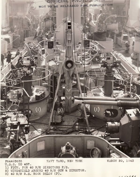
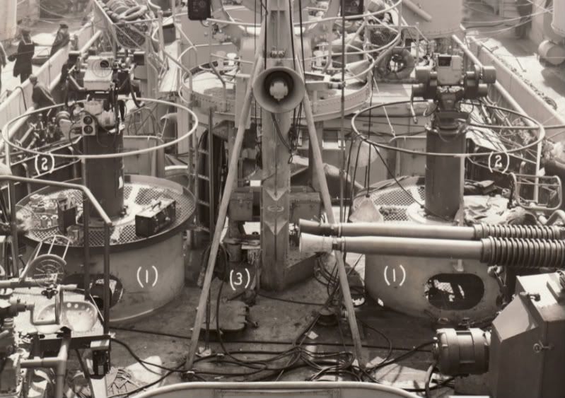
Here is a view of the two Mk 51 directors and searchlight platform ... first image is the whole photo and the second image is a close-up of the area. The Mk 51 directors were mounted on a platform installed atop a Mk 49 director foundation ring. This same Mk 49 ring can be seen on Fletchers and it wasn't uncommon to see Mk 51 directors mounted on it. The Mk 49 director WAS planned on being the STANDARD AA director, but it didn't pan out ... only about ten Benson-Gleaves units received the Mk 49. If you look past the searchlight platform, you can see the aft end of the amidships deckhouse.
Rick - I noticed the metal struts supporting the rear mast in place of the cable stays that were (I thought) typical of the earlier configurations. Was this something generally added along with the 40mm mounts? Barry
The tripod "struts" were a refinement and I'm not sure if all Benson-Gleaves got them. Emmons had this tripod in October-November 1942 with the quad 1.1-in mount and I suspect she had it when completed. The Mainmast got taller in mid-war when they started to add the HF/DF array atop the mast which did required even heavier reinforcement struts.
New member from Norway, why haven`t i spotted this site before?, been building models since childhood, 46 years old now (sorry my english) a`m coldwar threefifty fan and i`ve been ten years away from this hobby, only built aircraftmodels thats never finished. i have just bought Livermore and it is so fantastic, Now ive forced my hobby bench into the livingroom and is enjoying this masterpiece from Dragon, also iv ordered GMM`s PE set from WEM, this model i hope, is the future. thank you.
I have a question, didn`t the Gleaves class have sonar? i thougth all destroyers of wwll had sonar, well this model of USS Livermore don`t have it, or is it hidden in the hull? where can i find info about that?.
Yes the Benson-Gleaves destroyers had a sonar, actually some units had TWO sonars for a short period. All fleet destroyers were suppose to have two different types of sonar, but shortages because of DE construction caused a reduction to one sonar. I'm not sure where the standard sonar dome was located ... it was fixed ... the sonar transmitter itself was retractable. At NARA, I found photos of Plunkett's (DD-431) sonar dome removed after it hit an obstruction entering a port in UK ... sheared the bottom off. I didn't scan the images at the time as being of little value to me. I should have. It really showed the construction of these domes and the shape ... kind of an oval cross-section shape like a fat rudder. Likely the dome was located below either mount 51 or mount 52 just off centerline. I have been researching photos at NARA (National Archives) and at other locations for some time and almost NEVER find photos of the sonar dome during WWII. I think the equipment was VERY sensitive and I suspect that photos would have been classified and wasn't done often. After WWII, photos of the dome can be seen more often, but new and improved sonars appeared starting as early as 1945.
The DML Benson and Gleaves kits didn't include the sonar dome. The Gearing kit does include the sonar dome.
The lack of sonar domes on the Dragon kits is totally my fault. I left them off the final model. The dome is very much like the one on the Gearing and in the same general location.
Thanks, i was afraid it was a stupid question, it wasnt ?, i am getting WWIIser.
My only and only complaint about the USS Livermore, is that the deck on middle and aft deckhouses, have cratered, anti skid moulded in, no way i am gonna use decals on top of that. Wonder why Dragon did that? its very hard to remove that, than adding "PE net" if any ship had it. wish i could build all these "Dragons"
Last edited by bearcat on Mon May 18, 2009 2:54 pm, edited 1 time in total.
Yes, i`ve thougth of that, what sort of paint would you use? i am afraid it will take more than three layers of my humbrol enamel paint to cover it, but that should work.
I use ModelMaster Acrylics. In this case you want the decals to stand out a bit as they represent rubber tiles. Maybe we should hear from some who have successfully added the decals.
I used Aircraft modeling techniques for the non-skid walkways. I applied Future before decaling and used Micro Sol to soften and set the decals. Once dry, I applied another coat of future. This picture shows the result. When I flat coated last weekend - no silvering. This is USS Lansdowne (DD-486) July 1942. I am building it for IPMS-USA and the build is in the reviews section. I am in the process of adding all of the small details and remaining PE.
Last edited by Cadman on Fri May 15, 2009 10:10 pm, edited 1 time in total.
Reason:Link added
I think am going to use thin plastic plate for the decals under the 20mm on the center deckhouse, then leave it like that and paint the aft deckhouse as you explained, thanks
In the DRAGON USS Buchanan kit, there are three pieces, A40, A41, A42.
I was wondering if any of you, out there, can identify any of these as being a Mk. VI Fire Control Computer?
Or, if not, then does anyone have photo of a Mk. VI Fire Control Computer. There was one atop the USS Oyster Bay AGP-6, and I'd like to place it on my model. I only have top views in my drawings, no profile one, nor any drawings specific to the fire control equipment, just the platforms for them.
Thank you, in advance, for any help you can provide.
Im new to this forum, so please forgive my lack of knowledge, its going to take a loooong time to get as clued in as many of you here. Ive searched all 24 pages and havent found an answer for the question I have, although I may have missed it. Im building the Buchanan as she was fitted out after her yard period at MINY in '44. Part way into the build I noticed from the photos available that a centerline platform for a 20mm mount was added between mount 52 and the bridge. Can anyone direct me to some good photos of the shape of this platform and the support structure beneath it? I did see some ref. to it as fitted to others in the class, some having fully enclosed spaces underneath, but only a couple of blurry pictures of the type fitted to the Buchanan.
Thanks in advance for any help anyone has. Looking forward to seeing a lot of great models of this class on the website!
Hi
I am working on a USS Buchanan superdetailed version "summer 1944" (with her Dazzle camouflage) from version 1942.
As documentation, I have books 12 and 31 from Warships Pictorial .
I'm looking for informations (photos, plans, drawings) on the part of Breakwatrers located inside the circle.
image deleted
I also sought information on the shaft bracket plams.
image deleted
Finally I look for the decals markings on the mk37 and anti-skid rubber pads from Dragon decals.
In advance, thank you for your help.
Kind regards
Sebastien lausdat
France
PS: Although my English is very basic, if someone is interested, I can do a post on editing my USS Buchanan.
Last edited by Sebastien Lausdat on Sat Feb 13, 2010 9:29 am, edited 1 time in total.