Timmy C wrote:Tracy's got all you need there :thumbs_up_1:
Be aware, though, that some schemes may have gotten a tad lax in the post-war period. There's a shot of BB-63 Missouri entering New York in what should be MS-22, but the 5-N covers the entire hull, rather than just starting from below the lowest point of the deck.
Calling all Benson-class & Gleaves-class DD fans
Moderators: BB62vet, MartinJQuinn, Timmy C, Gernot, Olaf Held, Dan K, HMAS, ModelMonkey
-
ar
Re: Calling all USS Benson/Gleaves class (DD) fans
The camouflage measure that you see in the photo is Measure 12 Revised (1945 version). Not to be confused with Measure 12 (1945 version). Clear?
-
Timmy C

- Posts: 12448
- Joined: Mon Jan 10, 2005 6:00 pm
- Location: Ottawa, Canada
Re: Calling all USS Benson/Gleaves class (DD) fans
Ah ha, thanks! I've had that question in the Iowa class thread for a while, but it seems to have been missed.
De quoi s'agit-il?
-
drdoom1337
- Posts: 1161
- Joined: Wed Apr 23, 2008 7:40 pm
- Location: New Jersey
Re: Calling all USS Benson/Gleaves class (DD) fans
Does anybody know which radar USS Gwin had when it was sunk? I Can't find information anywhere or good photographs!
-
Cliffy B

- Posts: 3125
- Joined: Sun Feb 01, 2009 3:55 pm
- Location: Hawaii
- Contact:
Re: Calling all USS Benson/Gleaves class (DD) fans
From looking at some photos and drawings the best I can tell is she had an SC above an SG.drdoom1337 wrote:Does anybody know which radar USS Gwin had when it was sunk? I Can't find information anywhere or good photographs!
Here's a drawing off navsource.
http://www.navsource.org/archives/05/0543308.jpg
I don't count the drawing as 100% accurate but I kinda doubt that she would have carried anything different at the time.
This photo is dated 2-23-1943 off Mare Island where she was overhauled, 5 months and her last trip stateside before she was sunk. Unless she was used for some experimental stuff I'd bet on an SC and SG set.
http://www.navsource.org/archives/05/0543301.jpg
Drawing Board:
1/700 Whiff USS Leyte and escorts 1984
1/700 Whiff USN Modernized CAs 1984
1/700 Whiff ASW Showdown - FFs vs SSGN 1984
Slipway:
1/700 Whiff USN ASW Hunter Killer Group Dio 1984
1/700 Whiff USS Leyte and escorts 1984
1/700 Whiff USN Modernized CAs 1984
1/700 Whiff ASW Showdown - FFs vs SSGN 1984
Slipway:
1/700 Whiff USN ASW Hunter Killer Group Dio 1984
-
Rick E Davis
- Posts: 3879
- Joined: Thu May 29, 2008 8:02 pm
Re: Calling all USS Benson/Gleaves class (DD) fans
Gwin was updated in early 1943 with two twin 40-mm mounts WITH MK-49 DIRECTORS (only one of ten Benson-Gleaves to get them and the only one of the early group (DD421-444)!!!) and the latest radar suite for that date (I believe that is when she got SG radar at this yard period).
-
Tracy White
- Posts: 10621
- Joined: Mon Jan 10, 2005 11:02 am
- Location: EG48
- Contact:
Re: Calling all USS Benson/Gleaves class (DD) fans
Tracy White -Researcher@Large
"Let the evidence guide the research. Do not have a preconceived agenda which will only distort the result."
-Barbara Tuchman
"Let the evidence guide the research. Do not have a preconceived agenda which will only distort the result."
-Barbara Tuchman
-
Rory Smith

- Posts: 21
- Joined: Fri Feb 11, 2005 3:10 pm
- Location: Richmond, Va.
Re: Calling all USS Benson/Gleaves class (DD) fans
Tracy White wrote:Hey Rory; you might want to read this review I wrote on a Squadron DD Camo book a couple of months ago; I covered and explained a bit about the Navy system so that the reader would know a bit more about why I was criticizing the book. ShipCamouflage.com also has a lot of information besides the database, including a library of the SHIPS-2 painting manuals the Navy issued during the war.
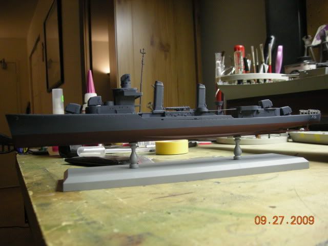
I have decided to go with the Polyscale 5-N and Deck Blue colors. I am using Tamiya Hull Red. Here are some progress photos. Thanks for your help guys.
" You can't dig a foxhole in a steel deck, but I damn sure tried." - History Channel
-
SweeperSkipper
- Posts: 68
- Joined: Tue Sep 15, 2009 1:36 am
- Location: Washington State
Re: Calling all USS Benson/Gleaves class (DD) fans
Hey Guy's wonderful job on the research and the builds so far in this thread 
I am currently planning a 1/48 scratch build of a Benson Gleaves class DD.
Has anyone been able to dig up a photo of one in Drydock? What i am after is a shot of the shaft struts, They seem to be different on my plans than say like for a Benham class or Fletcher Class.
Any help would be gratefull.
I am currently planning a 1/48 scratch build of a Benson Gleaves class DD.
Has anyone been able to dig up a photo of one in Drydock? What i am after is a shot of the shaft struts, They seem to be different on my plans than say like for a Benham class or Fletcher Class.
Any help would be gratefull.
Jesus Christ and General Jackson, this is the hottest potato they've handed me yet!
(Bull Halsey)
1/48 Benhan Class DD
1/48 ATF
1/48 DE
1/48 Gearing class DD
1/48 AM Minesweeper (Dry Docked)
1/24 AM Minesweeper (In for Refit)
(Bull Halsey)
1/48 Benhan Class DD
1/48 ATF
1/48 DE
1/48 Gearing class DD
1/48 AM Minesweeper (Dry Docked)
1/24 AM Minesweeper (In for Refit)
-
donalyah00

- Posts: 98
- Joined: Fri Aug 03, 2007 2:55 am
- Location: Wroclaw, Poland
Re: Calling all USS Benson/Gleaves class (DD) fans
Hello,
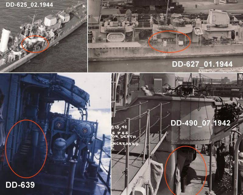
Preparing to build DD-429 USS Livermore I have been searching for the correct shape of the bridge ventillation. I have combined several photos to check how it looked on different Benson/Gleaves class ships:
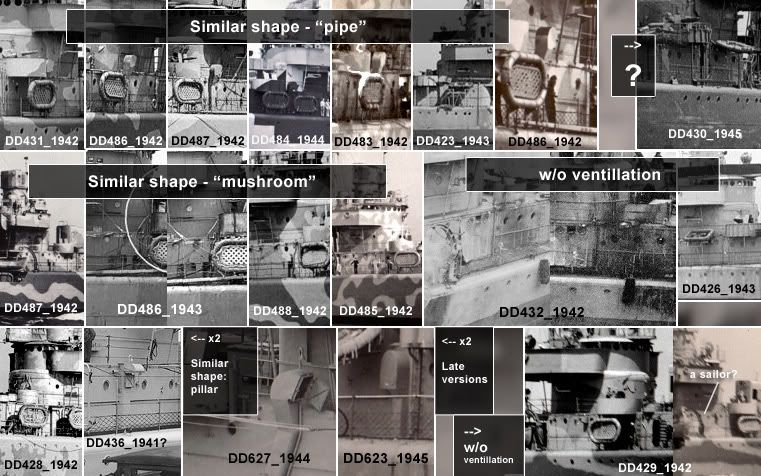
Looking at the photos I can tell that on the starboard of Livermore in 1942 there was no mushroom ventillator as supplied in Dragon kit. What type of ventillator has been mounted on the portboard? As there is no photo of Livermore's portboard from 1942 available I have checked her siblings built at Bath Iron Works shipyard (DD423, 424, 430, 437, 438, 457, 458) and again I could not find any clear photos of brigde's port side.
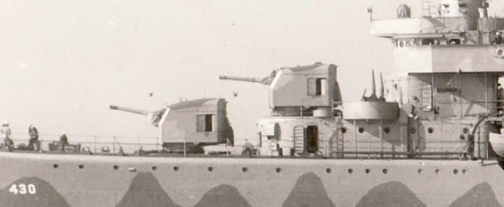
On the abovepresented collage there is one photo of DD-430 USS Eberle included (marked with the question sign) but I cannot tell what kind of ventillation shaft has been mounted. I begin to think it was a straight pillar - something similar to DD-428 or DD-436, but again the photo of USS Eberle is from 1945, probably after several modifications. Has anybody seen a clear photo of this detail onboard of the abovementioned Livermore siblings from 1942? TIA
Regards,
Marek
Preparing to build DD-429 USS Livermore I have been searching for the correct shape of the bridge ventillation. I have combined several photos to check how it looked on different Benson/Gleaves class ships:
Looking at the photos I can tell that on the starboard of Livermore in 1942 there was no mushroom ventillator as supplied in Dragon kit. What type of ventillator has been mounted on the portboard? As there is no photo of Livermore's portboard from 1942 available I have checked her siblings built at Bath Iron Works shipyard (DD423, 424, 430, 437, 438, 457, 458) and again I could not find any clear photos of brigde's port side.
On the abovepresented collage there is one photo of DD-430 USS Eberle included (marked with the question sign) but I cannot tell what kind of ventillation shaft has been mounted. I begin to think it was a straight pillar - something similar to DD-428 or DD-436, but again the photo of USS Eberle is from 1945, probably after several modifications. Has anybody seen a clear photo of this detail onboard of the abovementioned Livermore siblings from 1942? TIA
Regards,
Marek
-
Rick E Davis
- Posts: 3879
- Joined: Thu May 29, 2008 8:02 pm
Re: Calling all USS Benson/Gleaves class (DD) fans
Marek,
First off are you planning on building the LIVERMORE more or less straight from the box in a mid-late 1942 configuration with six 20-mm guns? I will assume so in the images I'm providing. The ventilation on the BENSON-GLEAVES dual-class was an issue throughout their career as far as I can tell. With the addition of a larger crew and more equipment (electronic being a big problem) the as built ventilation went through many changes as you have noticed. Also, the heavy seas of the North Atlantic caused many problems with water entry and different styles of vents were tried. Most vents on the forward part of the ship had doors to shut them off in bad weather, but this caused additional problems. So yes, the location and type of ventilators do vary. The early group of units (DD421-444) should be treated separate from the repeat units in many cases. But, some of the ventilation modifications were applied to ships across the groups. Some "styles" of ventilators were associated with a specific yard. If you are interested in modeling a ship at a specific timeframe and have limited views of that ship, try finding views of near sisters from the same DesDiv/DesRon if possible, because in my experience with this class ... they are MOST likely to be the closest. It does NOT work in every case, but is a good place to start.
The vents along the deckhouse on the main deck amidships is really an example of evolving ventilators.
If I have not addressed the period of interest of your build, let me know and I can try to find views for that time frame.
Below are a series of views of Bath Iron Works built GLEAVES class destroyers from the pre-war group.
USS GLEAVES (DD-423) as completed 27 May 1940. Note the use of mushroom vents.
USS NIBLACK (DD-424) as completed 16 July 1940. Note the mushroom vent and two vents of a different type with doors.
USS LIVERMORE (DD-429) after she was modified with six 20-mm guns replacing the 0.50-Cal MG's on 11 May 1942. Note that the mushroom vent has been modified to, I'm guessing, keep the water out from the front and seaward sides.
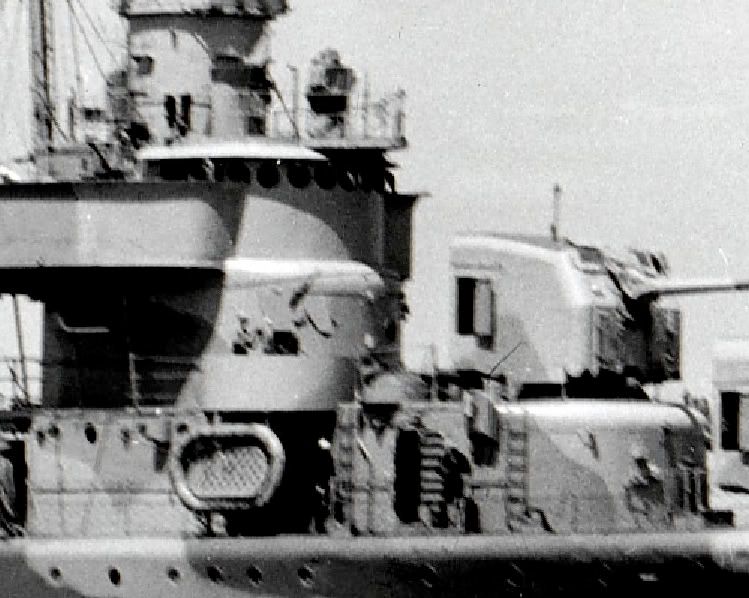
USS ERBELE (DD-430) also after she has received her six 20-mm Mod on 12 June 1942. Both ships were modified at Boston Navy Yard. Note, same type mushroom vent as used on LIVERMORE.
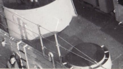
USS WOOLSEY (DD-437) on 2 February 1942 showing the top view of this revised mushroom vent. Looks to be a simple "ring shield" mounted around the original mushroom vent to help block off water entry.
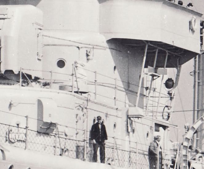
USS LIVERMORE (DD-429) after she received two twin 40-mm mounts on 5 June 1943 at New York Navy Yard. Not a real good view, but the vents have been changed to completely different types.
USS LIVERMORE (DD-429) a couple of months later on 4 August 1943 showing the quite different design of the vents on the portside.
First off are you planning on building the LIVERMORE more or less straight from the box in a mid-late 1942 configuration with six 20-mm guns? I will assume so in the images I'm providing. The ventilation on the BENSON-GLEAVES dual-class was an issue throughout their career as far as I can tell. With the addition of a larger crew and more equipment (electronic being a big problem) the as built ventilation went through many changes as you have noticed. Also, the heavy seas of the North Atlantic caused many problems with water entry and different styles of vents were tried. Most vents on the forward part of the ship had doors to shut them off in bad weather, but this caused additional problems. So yes, the location and type of ventilators do vary. The early group of units (DD421-444) should be treated separate from the repeat units in many cases. But, some of the ventilation modifications were applied to ships across the groups. Some "styles" of ventilators were associated with a specific yard. If you are interested in modeling a ship at a specific timeframe and have limited views of that ship, try finding views of near sisters from the same DesDiv/DesRon if possible, because in my experience with this class ... they are MOST likely to be the closest. It does NOT work in every case, but is a good place to start.
The vents along the deckhouse on the main deck amidships is really an example of evolving ventilators.
If I have not addressed the period of interest of your build, let me know and I can try to find views for that time frame.
Below are a series of views of Bath Iron Works built GLEAVES class destroyers from the pre-war group.
USS GLEAVES (DD-423) as completed 27 May 1940. Note the use of mushroom vents.
USS NIBLACK (DD-424) as completed 16 July 1940. Note the mushroom vent and two vents of a different type with doors.
USS LIVERMORE (DD-429) after she was modified with six 20-mm guns replacing the 0.50-Cal MG's on 11 May 1942. Note that the mushroom vent has been modified to, I'm guessing, keep the water out from the front and seaward sides.
USS ERBELE (DD-430) also after she has received her six 20-mm Mod on 12 June 1942. Both ships were modified at Boston Navy Yard. Note, same type mushroom vent as used on LIVERMORE.
USS WOOLSEY (DD-437) on 2 February 1942 showing the top view of this revised mushroom vent. Looks to be a simple "ring shield" mounted around the original mushroom vent to help block off water entry.
USS LIVERMORE (DD-429) after she received two twin 40-mm mounts on 5 June 1943 at New York Navy Yard. Not a real good view, but the vents have been changed to completely different types.
USS LIVERMORE (DD-429) a couple of months later on 4 August 1943 showing the quite different design of the vents on the portside.
-
donalyah00
- Posts: 98
- Joined: Fri Aug 03, 2007 2:55 am
- Location: Wroclaw, Poland
Re: Calling all USS Benson/Gleaves class (DD) fans
Rick,
A Big thank you for those detailed close-ups! Yes, I am building Livermore in her May 1942 configuration (w/o the Mk 12 array - to make my model a bit unique) - so your information is spot on. With detailing I will rely upon good photos of damaged USS Kearny DD-432, although coming from different shipyards, they served together on Atlantic in 1941. One clear photo of USS Kearny portboard shows the same vent shape as presented by you on the USS Eberle shot - I think I will use it for my Livermore.
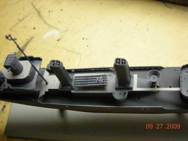
If I can have another question please - Dragon has molded two rectangular, flat boxes on both sides of stern superstrcture. I could not see them on any photos (I have access to Steve Wiper's Buchanan photo-book and Navsource on-line photo archives). On several photos one can see a row of pipes(?) in this place. I have heard an opinion, it was a rack for depth charges mounting tubes. I have removed those moulded-in boxes from the deck of my model, but I would like to replace them with the tubes.
Photos shown above are from later period of the war(apart from DD-490) and late members of the B/G class. I am wondering if this is a good idea for early vessels and early war-period. If so, was it used on Livermore or her siblings in 1942?
Regards,
Marek
A Big thank you for those detailed close-ups!
If I can have another question please - Dragon has molded two rectangular, flat boxes on both sides of stern superstrcture. I could not see them on any photos (I have access to Steve Wiper's Buchanan photo-book and Navsource on-line photo archives). On several photos one can see a row of pipes(?) in this place. I have heard an opinion, it was a rack for depth charges mounting tubes. I have removed those moulded-in boxes from the deck of my model, but I would like to replace them with the tubes.
Photos shown above are from later period of the war(apart from DD-490) and late members of the B/G class. I am wondering if this is a good idea for early vessels and early war-period. If so, was it used on Livermore or her siblings in 1942?
Regards,
Marek
-
Tracy White
- Posts: 10621
- Joined: Mon Jan 10, 2005 11:02 am
- Location: EG48
- Contact:
Re: Calling all USS Benson/Gleaves class (DD) fans
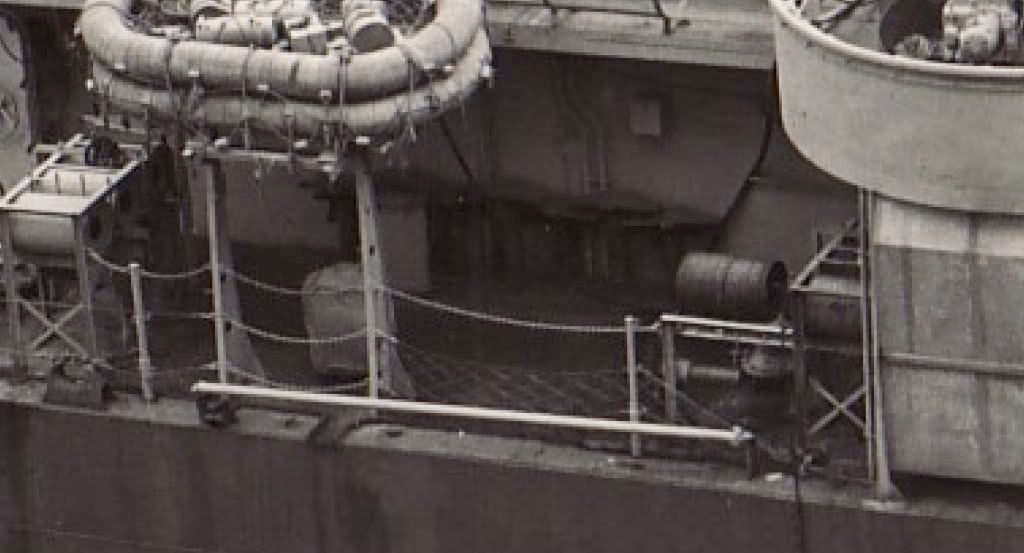
This is a shot from a Sims class(O'Brien) destroyer, but it shows what you're looking at; holders for the sabots for the K-gun depth charges.
- Attachments
-
Tracy White -Researcher@Large
"Let the evidence guide the research. Do not have a preconceived agenda which will only distort the result."
-Barbara Tuchman
"Let the evidence guide the research. Do not have a preconceived agenda which will only distort the result."
-Barbara Tuchman
-
Rick E Davis
- Posts: 3879
- Joined: Thu May 29, 2008 8:02 pm
Re: Calling all USS Benson/Gleaves class (DD) fans
Marek,
Tracy has provided an excellent close-up view of the 300-lb depth charge sabots or as I have seen them called arbors. If you are not familiar with the K-Gun system, the sabot/arbor was inserted into the launch tube (mortar by any other name) and the 300-lb depth charge was laid on the arbor and a chain strapped over the charge to keep it in place. Once launched, the chain released and the depth charge and arbor separated. The spare arbors were stored in all kinds of ways and places on BENSON-GLEAVES and FLETCHERS. The early BENSON-GLEAVES didn't have K-Guns installed as completed. A Y-Gun was mounted on the fantail in 1941 ... the Y-Gun if you don't know was basically left over from WWI and fired two charges in opposite directions. By the middle of 1942, the Y-Guns had been removed and up to six K-Guns were installed in the typical locations you see in the photos. (Early in 1942 when the K-Guns were first installed, some ships got two or four K-Guns and they kept the Y-Gun. Some ships had as many as EIGHT K-Guns, but they were reduced to six as a standard. EXCEPT in the Pacific where four were the standard sometime in early 1943.)
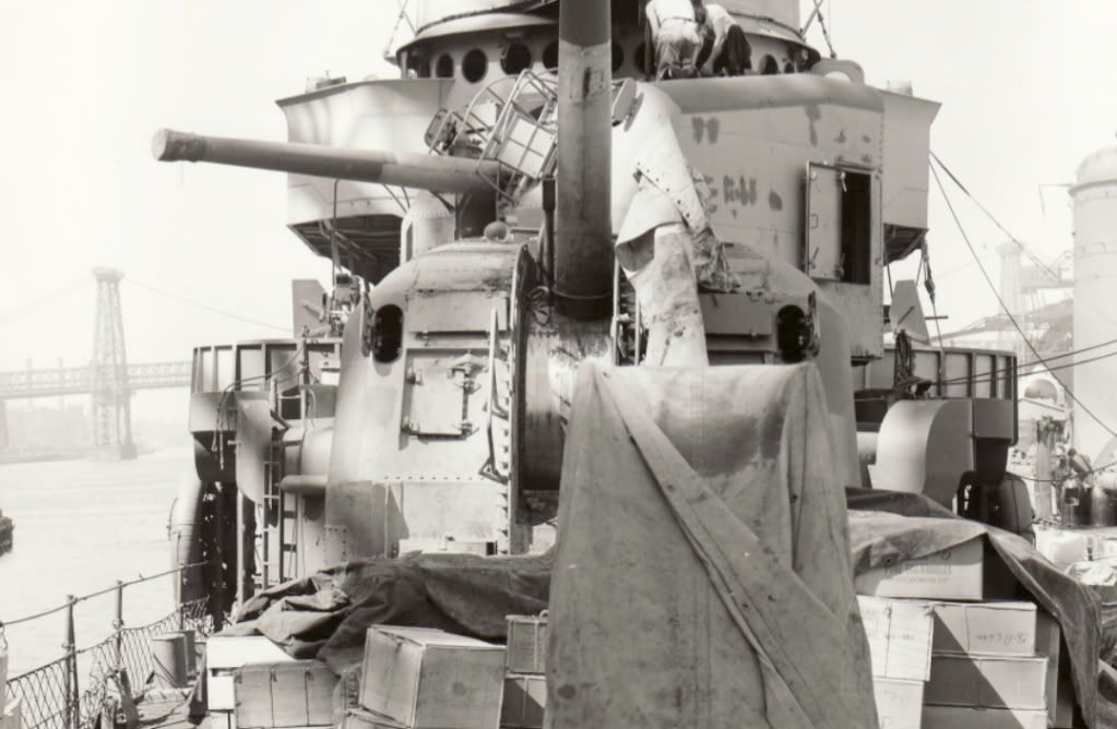
The images below were taken of Livermore on 11 May 1942 and after her twin 40-mm mounts were installed on 9 June 1943. The arbor post style of spare depth charge storage replaced with storage racks in 1943 and you can see the row of spare arbors in the June 1943 image. The May 1942 image isn't clear enough to see exactly what is located there. I suspect that they are arbors. For a time these ships carried spare depth charges beyond what were used in the arbor post storage method, enhance spare arbors were needed (later the spares were deleted to save weight). With the storage racks, the arbors needed to be stored and loaded for each depth charge round. Because the DML kits are a compromise between several different versions of the BENSON-GLEAVES class of ships, I'm not sure if the rectangular "boxes" you removed were a simplified depiction of the arbor storage or shows what look like storage bins on the newly commissioned early destroyers of this class. These bins may have shown up on the Buchanan, I just can't tell from the photo scans I have.
Tracy has provided an excellent close-up view of the 300-lb depth charge sabots or as I have seen them called arbors. If you are not familiar with the K-Gun system, the sabot/arbor was inserted into the launch tube (mortar by any other name) and the 300-lb depth charge was laid on the arbor and a chain strapped over the charge to keep it in place. Once launched, the chain released and the depth charge and arbor separated. The spare arbors were stored in all kinds of ways and places on BENSON-GLEAVES and FLETCHERS. The early BENSON-GLEAVES didn't have K-Guns installed as completed. A Y-Gun was mounted on the fantail in 1941 ... the Y-Gun if you don't know was basically left over from WWI and fired two charges in opposite directions. By the middle of 1942, the Y-Guns had been removed and up to six K-Guns were installed in the typical locations you see in the photos. (Early in 1942 when the K-Guns were first installed, some ships got two or four K-Guns and they kept the Y-Gun. Some ships had as many as EIGHT K-Guns, but they were reduced to six as a standard. EXCEPT in the Pacific where four were the standard sometime in early 1943.)
The images below were taken of Livermore on 11 May 1942 and after her twin 40-mm mounts were installed on 9 June 1943. The arbor post style of spare depth charge storage replaced with storage racks in 1943 and you can see the row of spare arbors in the June 1943 image. The May 1942 image isn't clear enough to see exactly what is located there. I suspect that they are arbors. For a time these ships carried spare depth charges beyond what were used in the arbor post storage method, enhance spare arbors were needed (later the spares were deleted to save weight). With the storage racks, the arbors needed to be stored and loaded for each depth charge round. Because the DML kits are a compromise between several different versions of the BENSON-GLEAVES class of ships, I'm not sure if the rectangular "boxes" you removed were a simplified depiction of the arbor storage or shows what look like storage bins on the newly commissioned early destroyers of this class. These bins may have shown up on the Buchanan, I just can't tell from the photo scans I have.
-
Rick E Davis
- Posts: 3879
- Joined: Thu May 29, 2008 8:02 pm
Re: Calling all USS Benson/Gleaves class (DD) fans
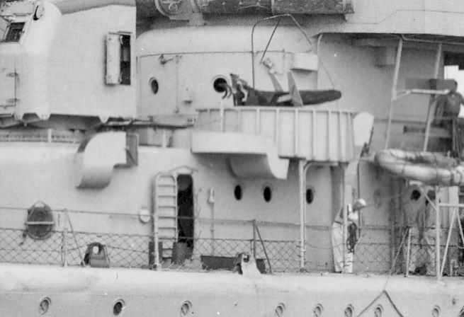
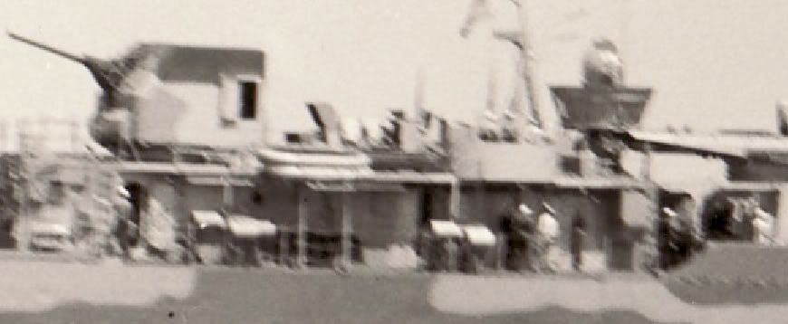
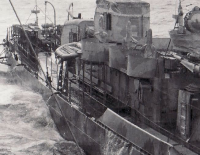
I just learned something I didn't know. In this February 1942 view of WOOLSEY (DD-437), I found out that the "folded-up things" I have seen on the bulkheads of early BENSON-GLEAVES were BENCHES!!! Dang, they look like park benches.
P.S. ... You can see that there are no K-guns and can just see the starboard arm of the Y-Gun on the fantail.
P.S. ... You can see that there are no K-guns and can just see the starboard arm of the Y-Gun on the fantail.
-
Tracy White
- Posts: 10621
- Joined: Mon Jan 10, 2005 11:02 am
- Location: EG48
- Contact:
Re: Calling all USS Benson/Gleaves class (DD) fans
That was me brain-fartingRick E Davis wrote:Tracy has provided an excellent close-up view of the 300-lb depth charge sabots or as I have seen them called arbors.
Tracy White -Researcher@Large
"Let the evidence guide the research. Do not have a preconceived agenda which will only distort the result."
-Barbara Tuchman
"Let the evidence guide the research. Do not have a preconceived agenda which will only distort the result."
-Barbara Tuchman
-
donalyah00
- Posts: 98
- Joined: Fri Aug 03, 2007 2:55 am
- Location: Wroclaw, Poland
Re: Calling all USS Benson/Gleaves class (DD) fans
Gentlemen, thank you again for such nice photos and infomative explanation.
DD-437 photo reminds me scenes from the decks of early WW2 French cruisers - real, forged-iron, park benches onboard. According to photos - mostly officers were using it.
Regards,
Marek
DD-437 photo reminds me scenes from the decks of early WW2 French cruisers - real, forged-iron, park benches onboard.
I think, it shows nicely the difference of submarine threat between Atlantic and Pacific theatres.Rick E Davis wrote:Some ships had as many as EIGHT K-Guns, but they were reduced to six as a standard. EXCEPT in the Pacific where four were the standard sometime in early 1943
Regards,
Marek
-
Capt652

- Posts: 404
- Joined: Wed Mar 21, 2007 5:59 pm
- Location: NW Lower Michigan
Re: Calling all USS Benson/Gleaves class (DD) fans
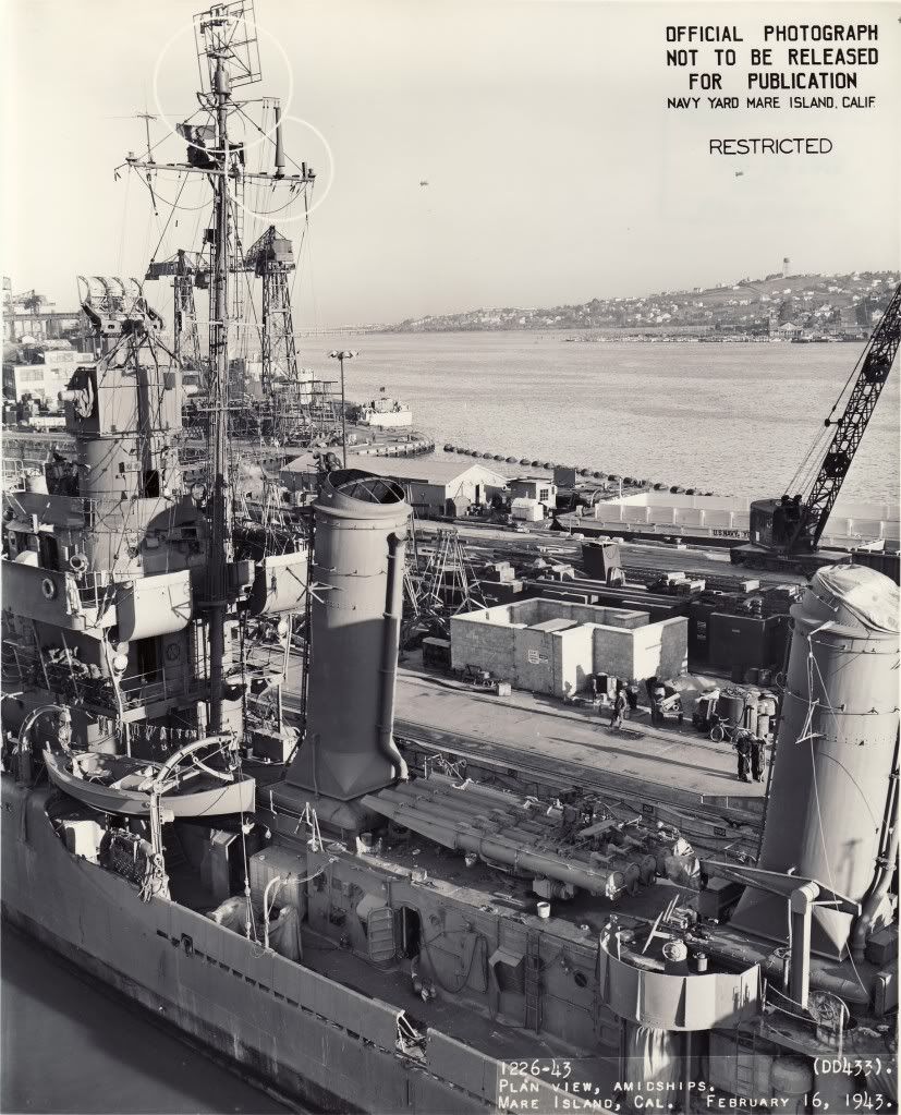
That photo of Gwin submitted by Mr. Davis, viewtopic.php?f=49&t=24483&start=390#p301598 shows a candlestick shaped antenna (I think it's a IFF) on the starboard side of the cross arm... were they common on DDs? I know I've seen them on aircraft carriers. For the size of this antenna it looks quite unsupported sitting on that narrow cross arm.
Timm
Timm
Timm Smith
Learn something new about the ship or your job every day. Ignorance is not bliss aboard a warship in wartime. Ignorance could cost the life of yourself, a shipmate, or the loss of the ship.
- Personal Information Booklet CV- 38
Learn something new about the ship or your job every day. Ignorance is not bliss aboard a warship in wartime. Ignorance could cost the life of yourself, a shipmate, or the loss of the ship.
- Personal Information Booklet CV- 38
-
SweeperSkipper
- Posts: 68
- Joined: Tue Sep 15, 2009 1:36 am
- Location: Washington State
Re: Calling all USS Benson/Gleaves class (DD) fans
Thought I would contribute this shot of the struts. Gleaves class DD 461.
- Attachments
-
- forrest.jpg (16.59 KiB) Viewed 4046 times
Jesus Christ and General Jackson, this is the hottest potato they've handed me yet!
(Bull Halsey)
1/48 Benhan Class DD
1/48 ATF
1/48 DE
1/48 Gearing class DD
1/48 AM Minesweeper (Dry Docked)
1/24 AM Minesweeper (In for Refit)
(Bull Halsey)
1/48 Benhan Class DD
1/48 ATF
1/48 DE
1/48 Gearing class DD
1/48 AM Minesweeper (Dry Docked)
1/24 AM Minesweeper (In for Refit)
-
Rick E Davis
- Posts: 3879
- Joined: Thu May 29, 2008 8:02 pm
Re: Calling all USS Benson/Gleaves class (DD) fans
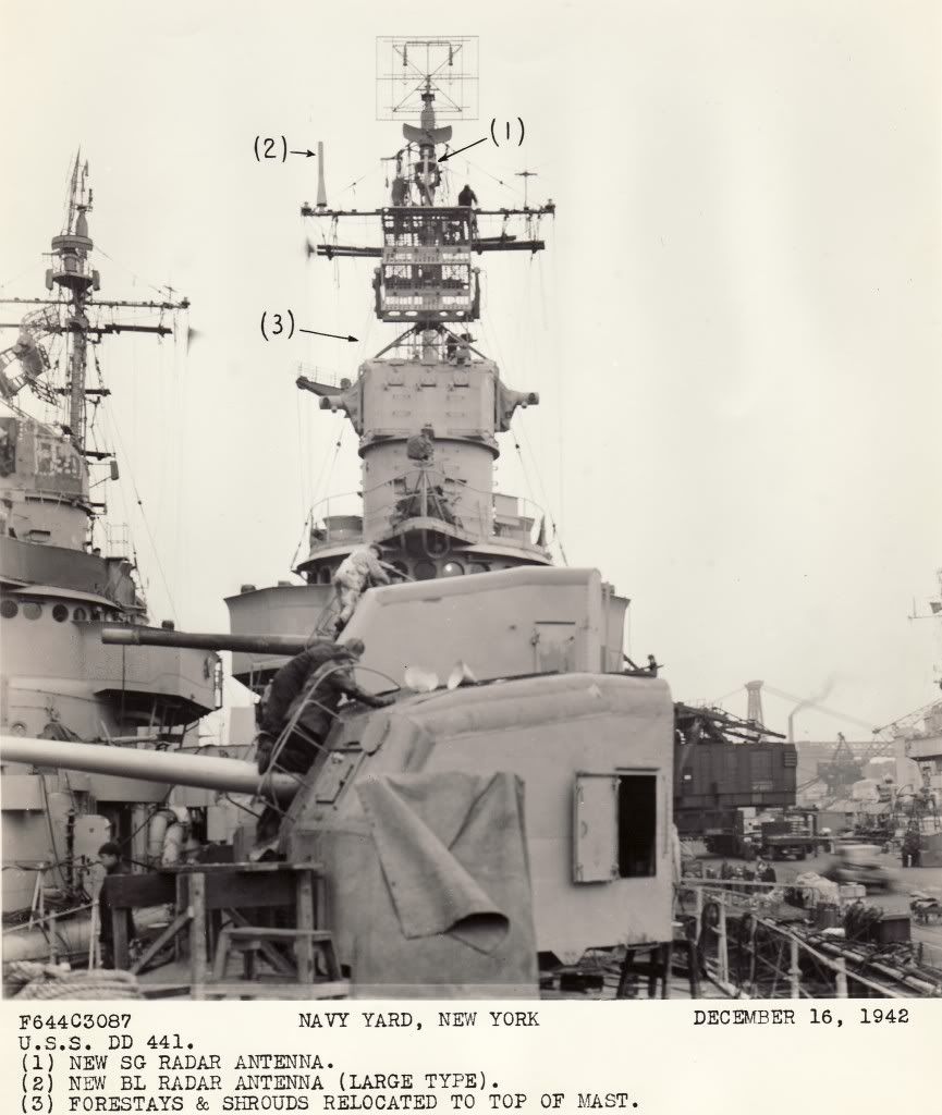
The antenna you have pointed out is the "BL Radar Antenna (Large Type)" as pointed out in the photo below. This system was an IFF system (Mk III) interrogator. It was more commonly seen on ships of all sizes in the Pacific, particularly common on FLETCHERS in late 1942 and into 1943. If I remember right, they had problems with the BL system interfering with the search and fire control radars and it was replaced by a better system. As for it being "unsupported" it would actually be quite light in weight and any whipping would not impact its intended operation. I had a hard time finding views of the BL Antenna installed on the early BENSON-GLEAVES units. It appears that they were only mounted for a short time ... starting in late 1942 and were gone by the Fall 1943.
The following description was found at the Naval Heritage and History Command website ... http://www.history.navy.mil/library/online/radar-13.htm ...
BL and *BM Mark III (A Band) Shipborne IR
DESCRIPTION: IFF Mark III (A band) shipborne interrogator-responsor. BM is improved version of BL.
USES: Interrogates Mark III transpondors (ABK, SCR-595, SCR-695, ABF, AN/APX-1, AN/APX-2) and gives an IFF reply on the radar scope.
PERFORMANCE: Reliable maximum ranges: for BL, 90 miles; for BM, 100 miles is expected.
TRANSPORTABILITY: Shipments of both sets include spares. BM has testing equipment as integral part. BL is packed for shipment in 2 units and weighs when crated a total of 375 lbs. BM is packed in 3 packages. Both sets are air transportable.
INSTALLATION: BL has 4 components weighing a total of approximately 274 lbs. The equipment component is 20" x 30" x 203/4" and weighs 250 lbs. BM has 2 components, weighing a total of 585 lbs. The equipment component is 30" x 20" x 203/4" and weighs 275 lbs.
PERSONNEL: Usually no additional personnel required -- the associated radar personnel serving.
POWER: Primary power required is 300 watts for BM, and 400 watts for BL, 110 v AC, 60 cycles. Source is ship's power or supply of associated radar.
-
Tracy White
- Posts: 10621
- Joined: Mon Jan 10, 2005 11:02 am
- Location: EG48
- Contact:
Re: Calling all USS Benson/Gleaves class (DD) fans
I can contribute a little here; I found these recently at the San Francisco Archives. These are the smaller type BL.
- Attachments
-
-
Tracy White -Researcher@Large
"Let the evidence guide the research. Do not have a preconceived agenda which will only distort the result."
-Barbara Tuchman
"Let the evidence guide the research. Do not have a preconceived agenda which will only distort the result."
-Barbara Tuchman