The Ship Model Forum

The Ship Modelers Source
It is currently Tue Jun 17, 2025 2:20 am

All times are UTC - 6 hours [ DST ]


Post new topic Reply to topic  [ 1214 posts ]  Go to page Previous  1 ... 18, 19, 20, 21, 22, 23, 24 ... 61  Next
Author Message
PostPosted: Mon Oct 05, 2009 3:21 am 
Offline
User avatar

Joined: Fri Aug 03, 2007 2:55 am
Posts: 98
Location: Wroclaw, Poland
Rick,

A Big thank you for those detailed close-ups! :) Yes, I am building Livermore in her May 1942 configuration (w/o the Mk 12 array - to make my model a bit unique) - so your information is spot on. With detailing I will rely upon good photos of damaged USS Kearny DD-432, although coming from different shipyards, they served together on Atlantic in 1941. One clear photo of USS Kearny portboard shows the same vent shape as presented by you on the USS Eberle shot - I think I will use it for my Livermore.
If I can have another question please - Dragon has molded two rectangular, flat boxes on both sides of stern superstrcture. I could not see them on any photos (I have access to Steve Wiper's Buchanan photo-book and Navsource on-line photo archives). On several photos one can see a row of pipes(?) in this place. I have heard an opinion, it was a rack for depth charges mounting tubes. I have removed those moulded-in boxes from the deck of my model, but I would like to replace them with the tubes.

Image

Photos shown above are from later period of the war(apart from DD-490) and late members of the B/G class. I am wondering if this is a good idea for early vessels and early war-period. If so, was it used on Livermore or her siblings in 1942?

Regards,
Marek

_________________
Best regards,
Marek

http://www.modelshipgallery.com/gallery/users/Marek-Targowicz/user-index.html


Top
 Profile  
Reply with quote  
PostPosted: Mon Oct 05, 2009 11:29 am 
Offline

Joined: Mon Jan 10, 2005 11:02 am
Posts: 10568
Location: EG48
This is a shot from a Sims class(O'Brien) destroyer, but it shows what you're looking at; holders for the sabots for the K-gun depth charges.


Attachments:
O'BrienSabot.jpg
O'BrienSabot.jpg [ 54.56 KiB | Viewed 2329 times ]

_________________
Tracy White -Researcher@Large

"Let the evidence guide the research. Do not have a preconceived agenda which will only distort the result."
-Barbara Tuchman
Top
 Profile  
Reply with quote  
PostPosted: Mon Oct 05, 2009 7:10 pm 
Offline

Joined: Thu May 29, 2008 8:02 pm
Posts: 3841
Marek,

Tracy has provided an excellent close-up view of the 300-lb depth charge sabots or as I have seen them called arbors. If you are not familiar with the K-Gun system, the sabot/arbor was inserted into the launch tube (mortar by any other name) and the 300-lb depth charge was laid on the arbor and a chain strapped over the charge to keep it in place. Once launched, the chain released and the depth charge and arbor separated. The spare arbors were stored in all kinds of ways and places on BENSON-GLEAVES and FLETCHERS. The early BENSON-GLEAVES didn't have K-Guns installed as completed. A Y-Gun was mounted on the fantail in 1941 ... the Y-Gun if you don't know was basically left over from WWI and fired two charges in opposite directions. By the middle of 1942, the Y-Guns had been removed and up to six K-Guns were installed in the typical locations you see in the photos. (Early in 1942 when the K-Guns were first installed, some ships got two or four K-Guns and they kept the Y-Gun. Some ships had as many as EIGHT K-Guns, but they were reduced to six as a standard. EXCEPT in the Pacific where four were the standard sometime in early 1943.)

The images below were taken of Livermore on 11 May 1942 and after her twin 40-mm mounts were installed on 9 June 1943. The arbor post style of spare depth charge storage replaced with storage racks in 1943 and you can see the row of spare arbors in the June 1943 image. The May 1942 image isn't clear enough to see exactly what is located there. I suspect that they are arbors. For a time these ships carried spare depth charges beyond what were used in the arbor post storage method, enhance spare arbors were needed (later the spares were deleted to save weight). With the storage racks, the arbors needed to be stored and loaded for each depth charge round. Because the DML kits are a compromise between several different versions of the BENSON-GLEAVES class of ships, I'm not sure if the rectangular "boxes" you removed were a simplified depiction of the arbor storage or shows what look like storage bins on the newly commissioned early destroyers of this class. These bins may have shown up on the Buchanan, I just can't tell from the photo scans I have.


Image

Image


Top
 Profile  
Reply with quote  
PostPosted: Mon Oct 05, 2009 7:50 pm 
Offline

Joined: Thu May 29, 2008 8:02 pm
Posts: 3841
I just learned something I didn't know. In this February 1942 view of WOOLSEY (DD-437), I found out that the "folded-up things" I have seen on the bulkheads of early BENSON-GLEAVES were BENCHES!!! Dang, they look like park benches.

P.S. ... You can see that there are no K-guns and can just see the starboard arm of the Y-Gun on the fantail.

Image


Top
 Profile  
Reply with quote  
PostPosted: Mon Oct 05, 2009 8:29 pm 
Offline

Joined: Mon Jan 10, 2005 11:02 am
Posts: 10568
Location: EG48
Rick E Davis wrote:
Tracy has provided an excellent close-up view of the 300-lb depth charge sabots or as I have seen them called arbors.


That was me brain-farting :censored_2:

_________________
Tracy White -Researcher@Large

"Let the evidence guide the research. Do not have a preconceived agenda which will only distort the result."
-Barbara Tuchman


Top
 Profile  
Reply with quote  
PostPosted: Tue Oct 06, 2009 3:15 am 
Offline
User avatar

Joined: Fri Aug 03, 2007 2:55 am
Posts: 98
Location: Wroclaw, Poland
Gentlemen, thank you again for such nice photos and infomative explanation. :thumbs_up_1:
DD-437 photo reminds me scenes from the decks of early WW2 French cruisers - real, forged-iron, park benches onboard. :smallsmile: According to photos - mostly officers were using it.

Rick E Davis wrote:
Some ships had as many as EIGHT K-Guns, but they were reduced to six as a standard. EXCEPT in the Pacific where four were the standard sometime in early 1943

I think, it shows nicely the difference of submarine threat between Atlantic and Pacific theatres.

Regards,
Marek

_________________
Best regards,
Marek

http://www.modelshipgallery.com/gallery/users/Marek-Targowicz/user-index.html


Top
 Profile  
Reply with quote  
PostPosted: Tue Oct 06, 2009 12:19 pm 
Offline
User avatar

Joined: Wed Mar 21, 2007 5:59 pm
Posts: 404
Location: NW Lower Michigan
That photo of Gwin submitted by Mr. Davis, viewtopic.php?f=49&t=24483&start=390#p301598 shows a candlestick shaped antenna (I think it's a IFF) on the starboard side of the cross arm... were they common on DDs? I know I've seen them on aircraft carriers. For the size of this antenna it looks quite unsupported sitting on that narrow cross arm.

Timm

_________________
Timm Smith
Learn something new about the ship or your job every day. Ignorance is not bliss aboard a warship in wartime. Ignorance could cost the life of yourself, a shipmate, or the loss of the ship.
- Personal Information Booklet CV- 38


Top
 Profile  
Reply with quote  
PostPosted: Tue Oct 06, 2009 3:19 pm 
Offline
User avatar

Joined: Tue Sep 15, 2009 1:36 am
Posts: 68
Location: Washington State
Thought I would contribute this shot of the struts. Gleaves class DD 461.


Attachments:
forrest.jpg
forrest.jpg [ 16.59 KiB | Viewed 3800 times ]

_________________
Jesus Christ and General Jackson, this is the hottest potato they've handed me yet!
(Bull Halsey)


1/48 Benhan Class DD
1/48 ATF
1/48 DE
1/48 Gearing class DD
1/48 AM Minesweeper (Dry Docked)
1/24 AM Minesweeper (In for Refit)
Top
 Profile  
Reply with quote  
PostPosted: Tue Oct 06, 2009 6:39 pm 
Offline

Joined: Thu May 29, 2008 8:02 pm
Posts: 3841
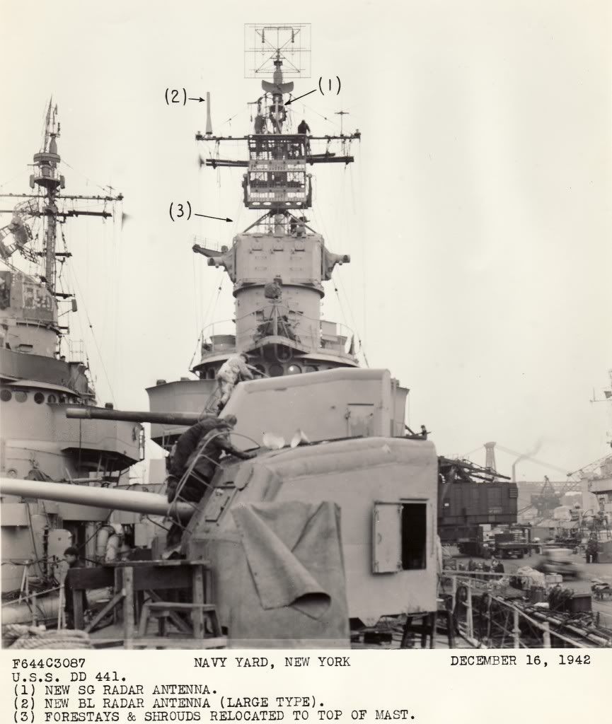
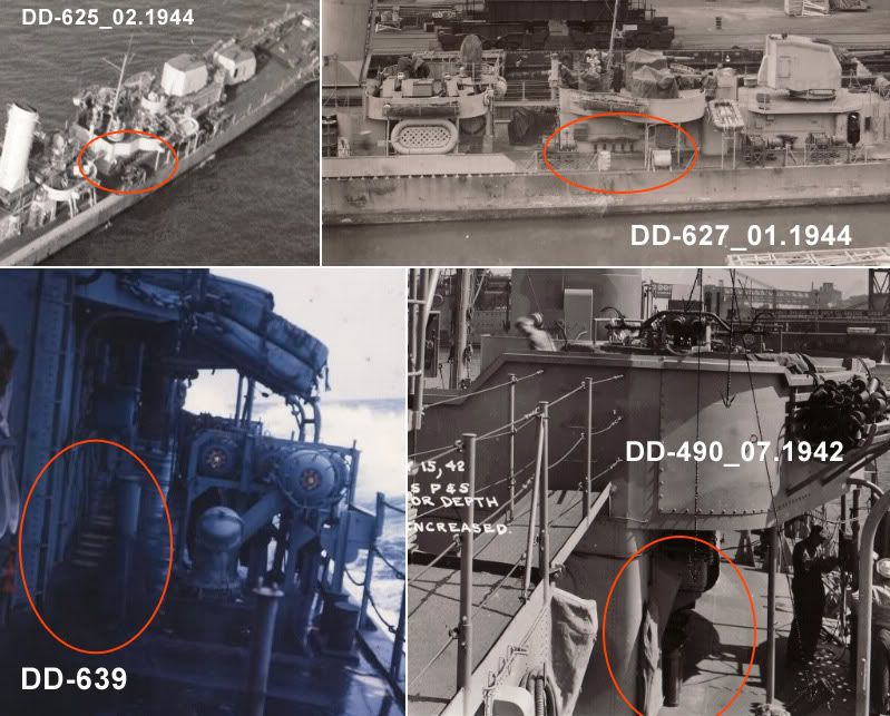
The antenna you have pointed out is the "BL Radar Antenna (Large Type)" as pointed out in the photo below. This system was an IFF system (Mk III) interrogator. It was more commonly seen on ships of all sizes in the Pacific, particularly common on FLETCHERS in late 1942 and into 1943. If I remember right, they had problems with the BL system interfering with the search and fire control radars and it was replaced by a better system. As for it being "unsupported" it would actually be quite light in weight and any whipping would not impact its intended operation. I had a hard time finding views of the BL Antenna installed on the early BENSON-GLEAVES units. It appears that they were only mounted for a short time ... starting in late 1942 and were gone by the Fall 1943.

The following description was found at the Naval Heritage and History Command website ... http://www.history.navy.mil/library/online/radar-13.htm ...

BL and *BM Mark III (A Band) Shipborne IR

DESCRIPTION: IFF Mark III (A band) shipborne interrogator-responsor. BM is improved version of BL.
USES: Interrogates Mark III transpondors (ABK, SCR-595, SCR-695, ABF, AN/APX-1, AN/APX-2) and gives an IFF reply on the radar scope.
PERFORMANCE: Reliable maximum ranges: for BL, 90 miles; for BM, 100 miles is expected.
TRANSPORTABILITY: Shipments of both sets include spares. BM has testing equipment as integral part. BL is packed for shipment in 2 units and weighs when crated a total of 375 lbs. BM is packed in 3 packages. Both sets are air transportable.
INSTALLATION: BL has 4 components weighing a total of approximately 274 lbs. The equipment component is 20" x 30" x 203/4" and weighs 250 lbs. BM has 2 components, weighing a total of 585 lbs. The equipment component is 30" x 20" x 203/4" and weighs 275 lbs.
PERSONNEL: Usually no additional personnel required -- the associated radar personnel serving.
POWER: Primary power required is 300 watts for BM, and 400 watts for BL, 110 v AC, 60 cycles. Source is ship's power or supply of associated radar.

Image


Top
 Profile  
Reply with quote  
PostPosted: Tue Oct 06, 2009 7:40 pm 
Offline

Joined: Mon Jan 10, 2005 11:02 am
Posts: 10568
Location: EG48
I can contribute a little here; I found these recently at the San Francisco Archives. These are the smaller type BL.


Attachments:
1943 February Radar Installation Plan - MkIII IFF.jpg
1943 February Radar Installation Plan - MkIII IFF.jpg [ 21.44 KiB | Viewed 2661 times ]
1943 Feb SG, SA, & BL-1 Radar Photos 02.jpg
1943 Feb SG, SA, & BL-1 Radar Photos 02.jpg [ 58.18 KiB | Viewed 2721 times ]

_________________
Tracy White -Researcher@Large

"Let the evidence guide the research. Do not have a preconceived agenda which will only distort the result."
-Barbara Tuchman
Top
 Profile  
Reply with quote  
PostPosted: Tue Oct 06, 2009 9:07 pm 
Offline

Joined: Thu May 29, 2008 8:02 pm
Posts: 3841
Tracy,

Cool. I wondered what the BL Small Type Antenna looked like and WHERE it was installed.


Top
 Profile  
Reply with quote  
PostPosted: Sat Oct 10, 2009 7:26 pm 
Offline
User avatar

Joined: Wed Apr 23, 2008 7:40 pm
Posts: 1157
Location: New Jersey
is it safe to say that Gwinn did not have a TBS antennea in 1943 on her main yard?

_________________
Image


Top
 Profile  
Reply with quote  
PostPosted: Sat Oct 10, 2009 8:33 pm 
Offline

Joined: Thu May 29, 2008 8:02 pm
Posts: 3841
On the GWIN photo I posted on the previous page, the TBS antenna was on her port main yard. TBS I believe was standard equipment by late 1942 on all USN destroyers.


Top
 Profile  
Reply with quote  
PostPosted: Sun Oct 11, 2009 12:06 am 
Offline
User avatar

Joined: Wed Apr 23, 2008 7:40 pm
Posts: 1157
Location: New Jersey
Darn I was hoping it didn't have TBS. I had one on the GMM PE set but I cut it out and I've lost it. Not sure what to do now :doh_1:

_________________
Image


Top
 Profile  
Reply with quote  
PostPosted: Sun Oct 11, 2009 5:22 pm 
Offline

Joined: Thu May 29, 2008 8:02 pm
Posts: 3841
Sorry about that, I could get a "CENSOR" brush out and work on the photo ... :smallsmile:


Top
 Profile  
Reply with quote  
PostPosted: Sun Oct 18, 2009 10:19 am 
Offline

Joined: Tue Feb 06, 2007 4:19 am
Posts: 128
Hello
I'm drawing the propeller shafts of the USS Buchanan to have them made.
Image
To validate my drawing, I want a clear plan and photos (especially at the hull) of the propeller shafts.
The propeller shafts are they dissymmetry (like the Fletcher class, Sumner and Gearing)?
I seek any information on the shape of the keel (map and photos) and all the details located below the waterline.
I looked at the pictures of Navscource. I have two Warship Pictorial and I even asked Steve Wiper who has no other informaton.
Any information is welcome and it is rather urgent.
Thanks
Sebastien Lausdat
france

See below the post of my models (update this week).
http://www.shipmodels.info/mws_forum/viewtopic.php?f=59&t=45205


Top
 Profile  
Reply with quote  
PostPosted: Sun Oct 18, 2009 2:02 pm 
Offline

Joined: Thu May 29, 2008 8:02 pm
Posts: 3841
Sebastien,

I don't have any photos of the shafts or for that matter many of this class out of the water and none showing the lower hull in any detail (out of 1,000+ images that is amazing). Try contacting Tim Dike (Cadman), he developed the BENSON-GLEAVES class kits from original drawings and should be able to answer your question.


Top
 Profile  
Reply with quote  
PostPosted: Fri Oct 23, 2009 4:52 am 
Offline
User avatar

Joined: Fri Aug 03, 2007 2:55 am
Posts: 98
Location: Wroclaw, Poland
Hello,

I have another question about underwater part of Benson/Gleaves class stern. Are there any photos/plans to see the complicated hull form around the rudder?
I am asking specifically about the flat area allowing rudder to rotate free - marked with red circles.
Image

On this photo from navsouce:
Image
one can see a bit different shape of hull in rudder area (especially on DD-462 in the background) - clean form without any "embossed" areas.

Regards,
Marek

_________________
Best regards,
Marek

http://www.modelshipgallery.com/gallery/users/Marek-Targowicz/user-index.html


Top
 Profile  
Reply with quote  
PostPosted: Fri Oct 23, 2009 3:03 pm 
Offline
Site Admin
Site Admin
User avatar

Joined: Sat Jan 08, 2005 4:31 pm
Posts: 3578
Location: Plattsburg, Missouri
The bottom rear should be much smoother. That is an translation error on my part. But the aft struts on your shafts need to be much closer together. They should be attached to a common base place in between both parts. I have some drawings of these parts that I plan on scanning. I will post them here when I can.

_________________
Timothy Dike
Owner & Administrator
ModelWarships.com


Top
 Profile  
Reply with quote  
PostPosted: Mon Oct 26, 2009 2:04 pm 
Offline
User avatar

Joined: Fri Aug 03, 2007 2:55 am
Posts: 98
Location: Wroclaw, Poland
Cadman wrote:
I have some drawings of these parts that I plan on scanning. I will post them here when I can.

It would be perfect, thank you! I will correct the shaft struts - they will need to be longer to nearly meet together in the centerline of the hull.

There are two more 'underwater' things:

First, on the DD-461&DD-462 photo I cannot see the quite big bulbous fairings of shaft's entry points into hull as they are moulded in the kit. Should they be smaller or be removed at all?

Second thing is the sonar dome on the 25th frame. I have found it on the plans of DD-618 from hnsa.org. Would it be mounted on early ships, e.g. USS Livermore in 1942?

Regards,
Marek

_________________
Best regards,
Marek

http://www.modelshipgallery.com/gallery/users/Marek-Targowicz/user-index.html


Top
 Profile  
Reply with quote  
Display posts from previous:  Sort by  
Post new topic Reply to topic  [ 1214 posts ]  Go to page Previous  1 ... 18, 19, 20, 21, 22, 23, 24 ... 61  Next

All times are UTC - 6 hours [ DST ]


Who is online

Users browsing this forum: No registered users and 2 guests


You can post new topics in this forum
You can reply to topics in this forum
You cannot edit your posts in this forum
You cannot delete your posts in this forum
You cannot post attachments in this forum

Jump to:  
Powered by phpBB® Forum Software © phpBB Group