Calling all Fletcher-class (DD-445) fans
Moderators: BB62vet, MartinJQuinn, Timmy C, Gernot, Olaf Held, Dan K, HMAS, ModelMonkey
-
les

- Posts: 819
- Joined: Mon Jan 10, 2005 3:01 pm
- Location: Port Townsend, WA
Re: Calling all USS Fletcher class (DD) fans
If you want to get into detail, I'd suggest you get the Floating Drydock cd/book on the Fletcher. Pretty much everything you wanted to know about a Fletcher.
Any ship larger than a Destroyer is a waste of metal.
-
bwross11

- Posts: 257
- Joined: Tue Nov 01, 2005 8:19 am
- Location: Medford, OR
Re: Calling all USS Fletcher class (DD) fans
Steve,
Les's suggestion of the Floating Drydock Plan book the Fletcher is a great reference on the class but it only covers above the waterline. To get the below waterline information you're seeking I highly recommend that you acquire the drydock plan of the Fletcher. This plan was used when the ships were put into drydock so that the keel blocks wouldn't be placed over intakes/discharges. On my 1/144 project I used this plan and was able to get all the info I needed.
Good luck with the project,
Bruce
Bruce
OSC USN-Ret

Currently on the building ways:
1/144 USS Stevens DD-479
1/144 USS Cook Inlet AVP-36
1/144 USS Walke DD-416
1/144 USS Preble DDG-46
OSC USN-Ret
Currently on the building ways:
1/144 USS Stevens DD-479
1/144 USS Cook Inlet AVP-36
1/144 USS Walke DD-416
1/144 USS Preble DDG-46
-
Rick E Davis
- Posts: 3869
- Joined: Thu May 29, 2008 8:02 pm
Re: Calling all USS Fletcher class (DD) fans
Steve,
You are getting into detail I don't have or I would have to spend hours to find. There are some drydock/building ways photos, but they don't provide all that much in the way of the kind of details you are asking about. Particularly on the very bottom of the hull.
The Floating Drydock e-Book is a good reference source ... http://www.floatingdrydock.com/books.html ... for $25.95 plus $4.95 shipping.
Also, DestroyerHistory.Org has a DVD for I think $30.00 with the drawings for the Fletcher class used by Bath Iron Works. Go here to order ... http://www.destroyerhistory.org/destroyers/store.html ... The DVD is kind of hard to follow at first, but there is a large amount of detail here if you keep digging. Hint, I printed out the index (Available online) and studied it to find the stuff I have wanted. The USS Abbot (DD-629), website has started to post these same drawings on line ... http://abbot.us/DD629/plans/ ... but, they are not all there yet.
-
Rotorhead

- Posts: 127
- Joined: Thu Dec 25, 2008 5:36 pm
Re: Calling all USS Fletcher class (DD) fans
OK guys............thanks for the pointers. I've been to all the suggested sites plus I just ordered the FD Hull plans for the Fletcher.
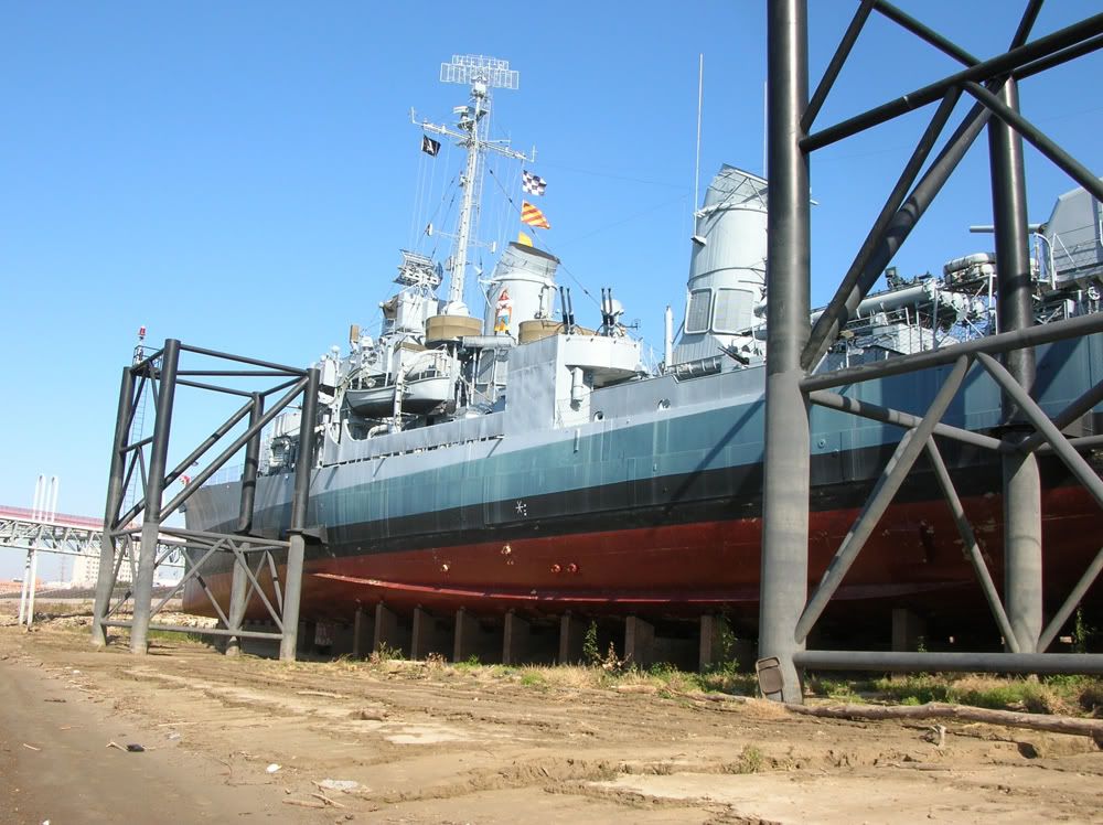
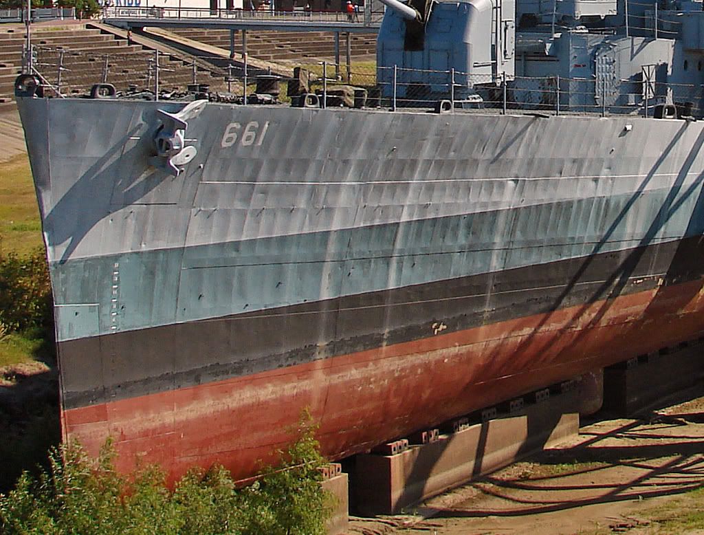
Let me rephrase my questions a bit if i could. I'm NOT looking for anyone to spend a lot of time searching for detailed answeres to my questions. I can see from prior posts that you guys are the experts. What I'm really looking for are photos of the hull in drydock, or as in the Kidd's case, sitting on blocks as a museum. I found some good photos of the Kidd at low tide when she was high and dry.
My question on the "Zincs" show up here. Is that what those squares are above the props?

My question on hull openings, I really don't care just where or what they are but as a modeler, I am interested. Here are a few of the Kidd, again at low tide. All the major openings have been capped. I just don't know what they look like UNcapped.

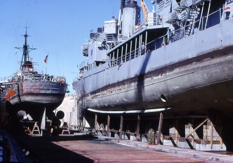
Here is a photo of a Gearing class (I think) in drydock.........and the large opening whith what looks like a vertical uptake.
I think that once modelers start on the 144 Fletcher all these questions are going to come up again.
So...............I'm looking for any Fletcher drydock photos that you might have and are willing to share.
Regards
Steve
Let me rephrase my questions a bit if i could. I'm NOT looking for anyone to spend a lot of time searching for detailed answeres to my questions. I can see from prior posts that you guys are the experts. What I'm really looking for are photos of the hull in drydock, or as in the Kidd's case, sitting on blocks as a museum. I found some good photos of the Kidd at low tide when she was high and dry.
My question on the "Zincs" show up here. Is that what those squares are above the props?
My question on hull openings, I really don't care just where or what they are but as a modeler, I am interested. Here are a few of the Kidd, again at low tide. All the major openings have been capped. I just don't know what they look like UNcapped.
Here is a photo of a Gearing class (I think) in drydock.........and the large opening whith what looks like a vertical uptake.
I think that once modelers start on the 144 Fletcher all these questions are going to come up again.
So...............I'm looking for any Fletcher drydock photos that you might have and are willing to share.
Regards
Steve
-
bwross11
- Posts: 257
- Joined: Tue Nov 01, 2005 8:19 am
- Location: Medford, OR
Re: Calling all USS Fletcher class (DD) fans
Steve,
Those squares above the screws are indeed the zinc protectors; which by the way for reference measure 12" x 6" x 1/2" and are mounted with four bolts in the corners. Now I pulled the copy I have of the shipyard drawings that Rick mentioned and they do not show the same arrangement as seen on your pictures of the Kidd. Could very well be that there was differences depending on which shipyard mounted them. Also, there were blocks mounted on the shaft bearing housings.
Some of the hull openings have a simple doubler plate around the opening and some had more elaborate grills installed; the best thing would be the previously mentioned shipyard drawings as there is an immense amount of information contained in them; I know that's why my Fletcher project got slowed down, trying to build to exact dimensions and at 1/144 that is sometimes a challenge!
I have more pictures of the Kidd similar to the ones you posted; nothing during her operational career that would be of help, sorry.
The very large opening that you pointed out on the Gearing is a discharge for the main seawater induction. Generally, the intakes where down closer to the keel and the discharges are higher at the turn of the bilge.
Hope this helps,
Bruce
Bruce
OSC USN-Ret
Currently on the building ways:
1/144 USS Stevens DD-479
1/144 USS Cook Inlet AVP-36
1/144 USS Walke DD-416
1/144 USS Preble DDG-46
OSC USN-Ret
Currently on the building ways:
1/144 USS Stevens DD-479
1/144 USS Cook Inlet AVP-36
1/144 USS Walke DD-416
1/144 USS Preble DDG-46
-
Rotorhead
- Posts: 127
- Joined: Thu Dec 25, 2008 5:36 pm
Re: Calling all USS Fletcher class (DD) fans
Bruce,
That certainly does help. I've already ordered the Floating Drydock CD. I've been looking at the Abbot blueprints, as well as some photos at the Kidd museum of a powerplant "trainer" apparatus. That trainer would be a great source of data on intakes and discharges.
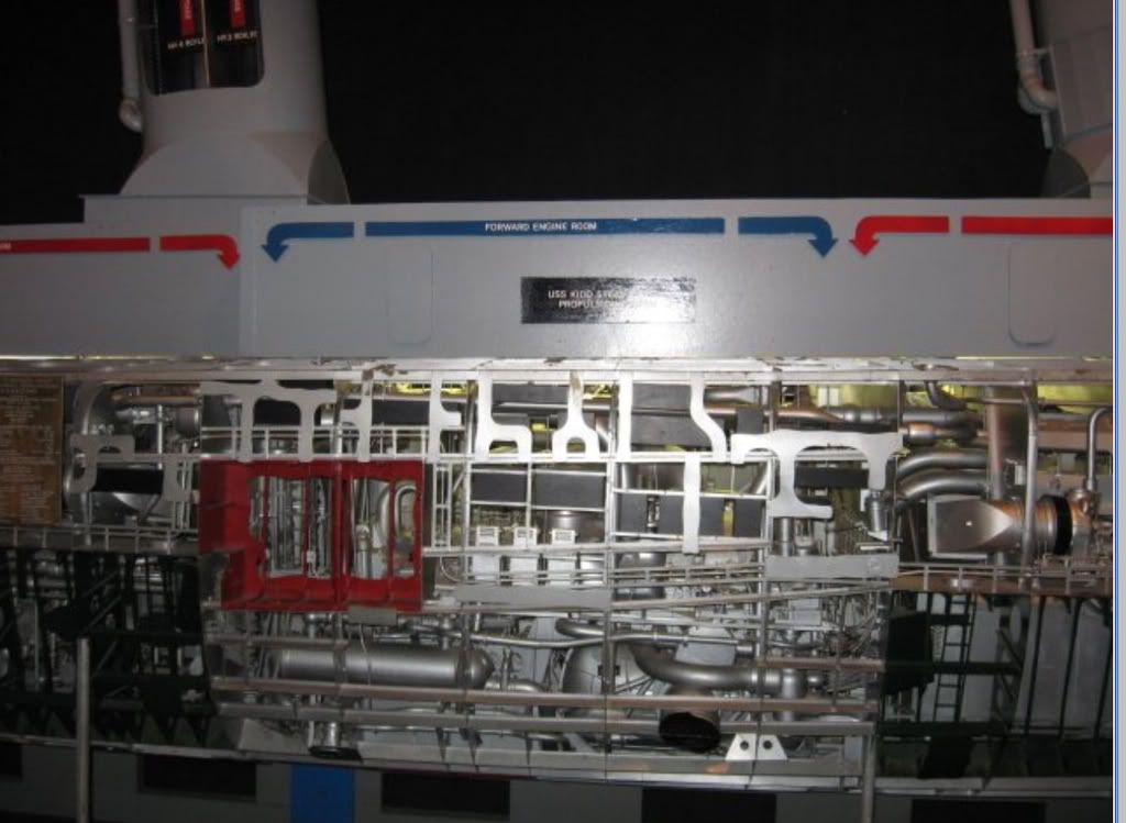
I need to find more of these.
Bruce.......what scale model were/are you doing on the Fletcher? I've got the Revell 1/144 kit of the Fletcher. It begs for more detail as it's rather basic in detail but looks good in shape and basic equipment. I don't need to be EXACT, but I'd like to be somewhat in the ballpark. The Kidd provides a wealth of infor for at least location of most ports.........except for the bottom.
Regards
Steve
That certainly does help. I've already ordered the Floating Drydock CD. I've been looking at the Abbot blueprints, as well as some photos at the Kidd museum of a powerplant "trainer" apparatus. That trainer would be a great source of data on intakes and discharges.
I need to find more of these.
Bruce.......what scale model were/are you doing on the Fletcher? I've got the Revell 1/144 kit of the Fletcher. It begs for more detail as it's rather basic in detail but looks good in shape and basic equipment. I don't need to be EXACT, but I'd like to be somewhat in the ballpark. The Kidd provides a wealth of infor for at least location of most ports.........except for the bottom.
Regards
Steve
-
Rick E Davis
- Posts: 3869
- Joined: Thu May 29, 2008 8:02 pm
Re: Calling all USS Fletcher class (DD) fans
Steve,
The Fletcher class had several builders and at least one major revision during construction of the class ... when they went to the Open bridge. So there likely are differences in details as built. Plus some ships, like the Kidd were in service for a long time after the war and may well have additional changes. But, the Fletcher was one of the lead ships and should have followed the original design drawings.
The BIW drawings DVD (and at Abbot's website) has many of the original Gibbs and Cox drawings supplied to the initial class builders for the original "Round-bridge" units. BIW built three "groups" during their production of the class ... the Round-bridge, the Initial Open-bridge with six 40-mm guns, and the Open-bridge with the ten 40-mm guns (the Open-bridges between these two are quite DIFFERENT) and the drawings have many differences between the groups. Many of the drawings for the first three BIW built/delivered Fletchers (Nicholas, O'Bannon, and Chevalier) are the same configuration as the Federal-built Fletcher (DD-445) through La Vallette (DD-448). The Revell 1/144 scale Fletcher kit as "out-of-the-box" only fits a very few of the original units of the class as delivered.
There is one thing I will mention. Awhile back, someone asked about the sonar location on Fletchers. I had a heck of a time trying to locate the sonar dome. I found TWO sonar locations on the BIW hull drawings. I found out later after re-reading reference books that the plan WAS to install two different sonars on Fletchers. But, because of the shortage of sonar units and priority of the DE's being the prime ASW ships ... the navy decided to only install one. To this day, I don't have a solid clue if the sonar was installed in the forward location or amidships under the bridge. I understand that the forward location is more likely. (As a side note the below bridge "Sonar" room eventually was retooled as the "Ice Cream Machine" room ... hence it likely was the one NOT used?)
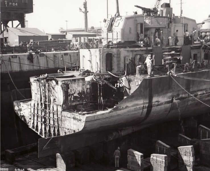
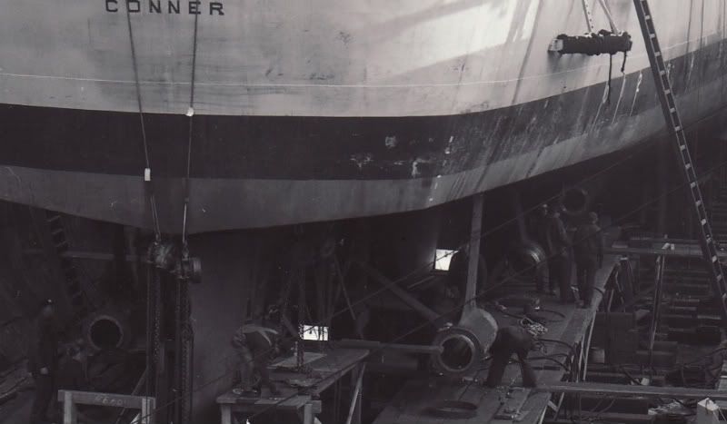
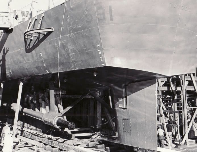
Here are I think ALL of the below waterline views I have scanned at NARA. I posted the first four of these on the Benson-Gleaves page to answer a question about the shaft brackets, because I didn't have any similar views for that dual-class. I like to model waterline and don't scan many below waterline views. I would scan any views that showed the sonar domes, but they must have been sensitive about taking photos of these, because I have found none unless they were real close-up views of damage ... which was a problem for the Benson-Gleaves units.
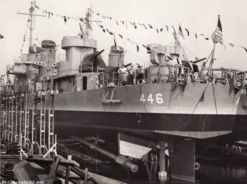
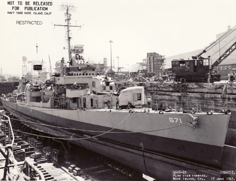
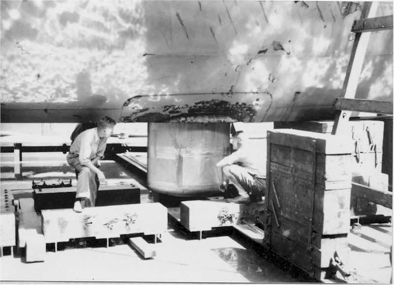
The first one is of Radford and may be of the most help, but as you can see details are thin. This is typical of "construction" shots ... stuff in the way. The other ships are: Sigsbee (DD-502), an early ship built by Federal under repair at Pearl Harbor in 1945, Conner (DD-582), Twiggs (DD-591) and the last one is a new post of Gatling (DD-671) in 1945 in drydock. Normall WWII drydock photos are taken from the dock looking down. Postwar views many times have photos taken from the bottom of the drydock.
Hope these help some,
The Fletcher class had several builders and at least one major revision during construction of the class ... when they went to the Open bridge. So there likely are differences in details as built. Plus some ships, like the Kidd were in service for a long time after the war and may well have additional changes. But, the Fletcher was one of the lead ships and should have followed the original design drawings.
The BIW drawings DVD (and at Abbot's website) has many of the original Gibbs and Cox drawings supplied to the initial class builders for the original "Round-bridge" units. BIW built three "groups" during their production of the class ... the Round-bridge, the Initial Open-bridge with six 40-mm guns, and the Open-bridge with the ten 40-mm guns (the Open-bridges between these two are quite DIFFERENT) and the drawings have many differences between the groups. Many of the drawings for the first three BIW built/delivered Fletchers (Nicholas, O'Bannon, and Chevalier) are the same configuration as the Federal-built Fletcher (DD-445) through La Vallette (DD-448). The Revell 1/144 scale Fletcher kit as "out-of-the-box" only fits a very few of the original units of the class as delivered.
There is one thing I will mention. Awhile back, someone asked about the sonar location on Fletchers. I had a heck of a time trying to locate the sonar dome. I found TWO sonar locations on the BIW hull drawings. I found out later after re-reading reference books that the plan WAS to install two different sonars on Fletchers. But, because of the shortage of sonar units and priority of the DE's being the prime ASW ships ... the navy decided to only install one. To this day, I don't have a solid clue if the sonar was installed in the forward location or amidships under the bridge. I understand that the forward location is more likely. (As a side note the below bridge "Sonar" room eventually was retooled as the "Ice Cream Machine" room ... hence it likely was the one NOT used?)
Here are I think ALL of the below waterline views I have scanned at NARA. I posted the first four of these on the Benson-Gleaves page to answer a question about the shaft brackets, because I didn't have any similar views for that dual-class. I like to model waterline and don't scan many below waterline views. I would scan any views that showed the sonar domes, but they must have been sensitive about taking photos of these, because I have found none unless they were real close-up views of damage ... which was a problem for the Benson-Gleaves units.
The first one is of Radford and may be of the most help, but as you can see details are thin. This is typical of "construction" shots ... stuff in the way. The other ships are: Sigsbee (DD-502), an early ship built by Federal under repair at Pearl Harbor in 1945, Conner (DD-582), Twiggs (DD-591) and the last one is a new post of Gatling (DD-671) in 1945 in drydock. Normall WWII drydock photos are taken from the dock looking down. Postwar views many times have photos taken from the bottom of the drydock.
Hope these help some,
-
bwross11
- Posts: 257
- Joined: Tue Nov 01, 2005 8:19 am
- Location: Medford, OR
Re: Calling all USS Fletcher class (DD) fans
Steve,
Rick is absolutely right in the information that he has provided; call me a heretic but you can probably put the zinc blocks in about any reasonable arrangement around the screws, shaft supports, and rudder and no one will be able to provide that you're wrong with all the variations that abounded! As far as the actual hull openings, I believe that you've got the right idea.
My project is the USS Stevens DD-479; I started this model back a few years ago when the Revell offering wasn't even a rumor. She's being built as the ship appeared in early 1943 with the aircraft catapult aboard. I am a slow builder and the addition of all the detail data I have received over the years means that I keep trying to put more detail into the model which in turn slows things down.
This picture is a bit old but at least you get the idea.
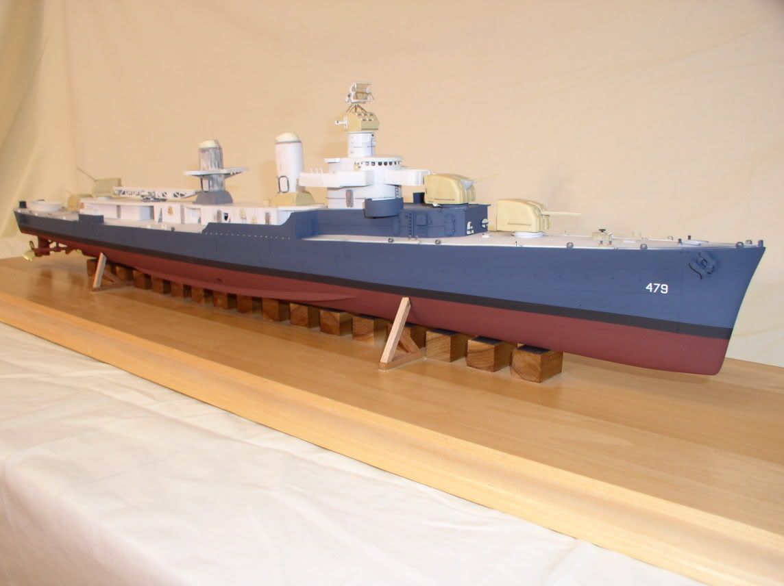
More can be seen in the scratchbuilding section; just do a search for USS Stevens in 1/144 scale; hasn't been updated lately so its on the third or fourth page by now!
Best, and good modeling,
Bruce
Rick is absolutely right in the information that he has provided; call me a heretic but you can probably put the zinc blocks in about any reasonable arrangement around the screws, shaft supports, and rudder and no one will be able to provide that you're wrong with all the variations that abounded! As far as the actual hull openings, I believe that you've got the right idea.
My project is the USS Stevens DD-479; I started this model back a few years ago when the Revell offering wasn't even a rumor. She's being built as the ship appeared in early 1943 with the aircraft catapult aboard. I am a slow builder and the addition of all the detail data I have received over the years means that I keep trying to put more detail into the model which in turn slows things down.
This picture is a bit old but at least you get the idea.
More can be seen in the scratchbuilding section; just do a search for USS Stevens in 1/144 scale; hasn't been updated lately so its on the third or fourth page by now!
Best, and good modeling,
Bruce
Bruce
OSC USN-Ret
Currently on the building ways:
1/144 USS Stevens DD-479
1/144 USS Cook Inlet AVP-36
1/144 USS Walke DD-416
1/144 USS Preble DDG-46
OSC USN-Ret
Currently on the building ways:
1/144 USS Stevens DD-479
1/144 USS Cook Inlet AVP-36
1/144 USS Walke DD-416
1/144 USS Preble DDG-46
-
Rotorhead
- Posts: 127
- Joined: Thu Dec 25, 2008 5:36 pm
Re: Calling all USS Fletcher class (DD) fans
Rick and Bruce, you've helped tremendously. I thank you for your research and sharing.
Again, I'm not a rivet counter but I do consider myself very observant. As of this moment i do not have a particular ship in mind for my build. I now my choices are rather limited. Not a problem. Right now I'm gathering generic Fletcher data. The hull will certainly be generic as there is no-way i can get a correct hull. Weather decks configuration will be more important than the hull.
But since I'm on the hull right now.............the sonar dome:
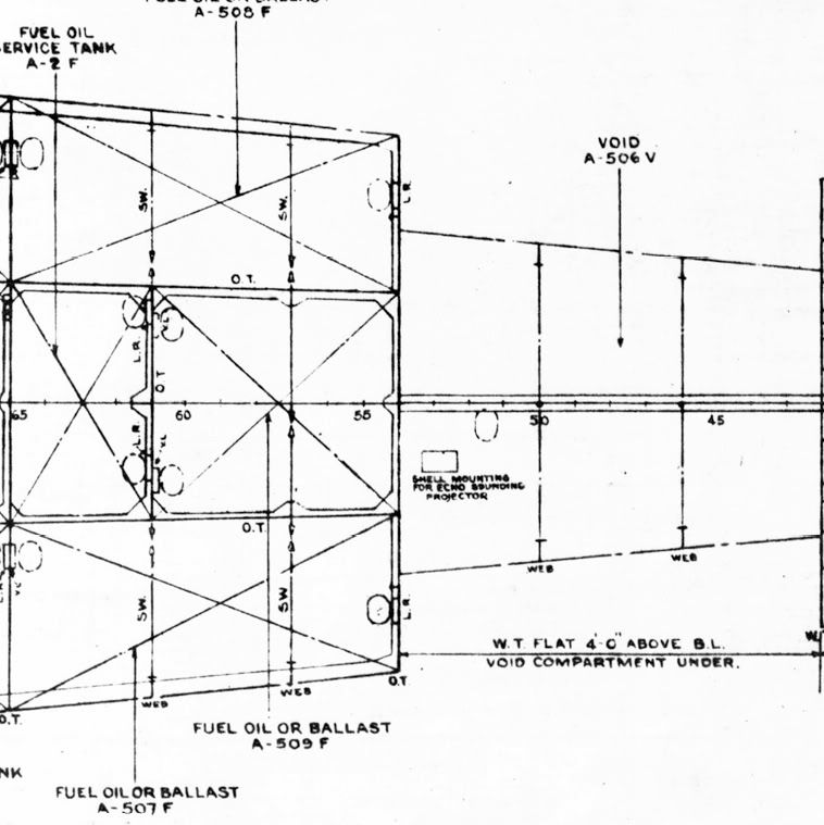
Here is a cropped drawing from the DD-502 Sigsbee's plans showing the forward location right of the keel. Interesting in that the bow appears to be to the right and the dome is on port side of the keel.
Here is a drydock photo of the extended sonar dome on an unidentified Fletcher:
Here is a photo of the current day Kidd with the dome extended. It too "Looks" to be on port side.
Bruce, I will check out that thread, thanks.
Regards
Steve
Again, I'm not a rivet counter but I do consider myself very observant. As of this moment i do not have a particular ship in mind for my build. I now my choices are rather limited. Not a problem. Right now I'm gathering generic Fletcher data. The hull will certainly be generic as there is no-way i can get a correct hull. Weather decks configuration will be more important than the hull.
But since I'm on the hull right now.............the sonar dome:
Here is a cropped drawing from the DD-502 Sigsbee's plans showing the forward location right of the keel. Interesting in that the bow appears to be to the right and the dome is on port side of the keel.
Here is a drydock photo of the extended sonar dome on an unidentified Fletcher:
Here is a photo of the current day Kidd with the dome extended. It too "Looks" to be on port side.
Bruce, I will check out that thread, thanks.
Regards
Steve
-
Rick E Davis
- Posts: 3869
- Joined: Thu May 29, 2008 8:02 pm
Re: Calling all USS Fletcher class (DD) fans
Steve,
The drawing "grabs" I posted showing the Sonar location with dimensions are on Page 21 of this string. I think the first drawing is where the sonar was installed and where you seen it on Kidd. Not sure of what sonar was used in the 1950's on this class.
The drawing "grabs" I posted showing the Sonar location with dimensions are on Page 21 of this string. I think the first drawing is where the sonar was installed and where you seen it on Kidd. Not sure of what sonar was used in the 1950's on this class.
-
whaynes

- Posts: 294
- Joined: Mon Feb 27, 2006 10:32 pm
- Location: South Carolina
Re: Calling all USS Fletcher class (DD) fans
Does anyone have any pictures/details of the square vents located on the deckhouse bulkheads? I've looked through the Fletcher Plans Book and other plans I have but all I see is a vague dark outline . Thanks for any help.
Walt Haynes
Walt Haynes
-
Rick E Davis
- Posts: 3869
- Joined: Thu May 29, 2008 8:02 pm
Re: Calling all USS Fletcher class (DD) fans
Walt,
Where exactly are you needing views of the deckhouse? Not sure what vents (or possible other features) you need more details on.
Rick
Where exactly are you needing views of the deckhouse? Not sure what vents (or possible other features) you need more details on.
Rick
-
whaynes
- Posts: 294
- Joined: Mon Feb 27, 2006 10:32 pm
- Location: South Carolina
Re: Calling all USS Fletcher class (DD) fans
Rick, I'm looking at Floating Drydock's 1/96 plans of USS O'Bannon. On the main deckhouse bulkheads there are 3 vents which appear to be about 3 feet square on the port side and 2 on the starboard side. On the after deck house there are 3 on each side. Some pictures I have seen show a solid plate covering the grill openings. There also appears to be one on the forward superstructure beneath the No. 2 5 inch gun. I'm sorry I can't be more specific.
Walt
Walt
-
Rick E Davis
- Posts: 3869
- Joined: Thu May 29, 2008 8:02 pm
Re: Calling all USS Fletcher class (DD) fans
Walt,
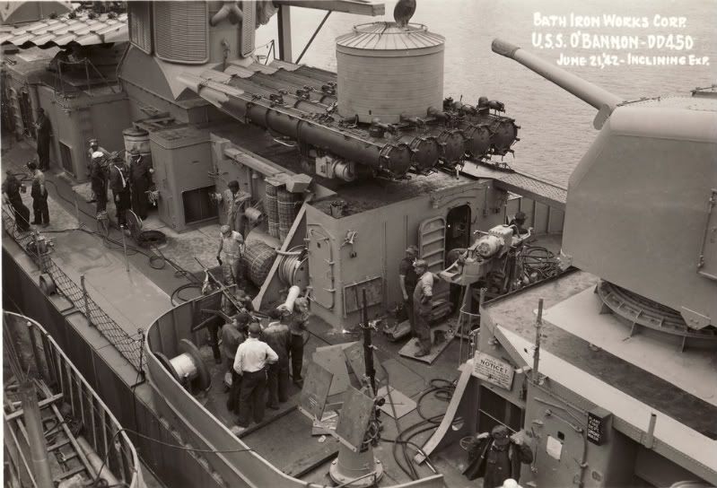
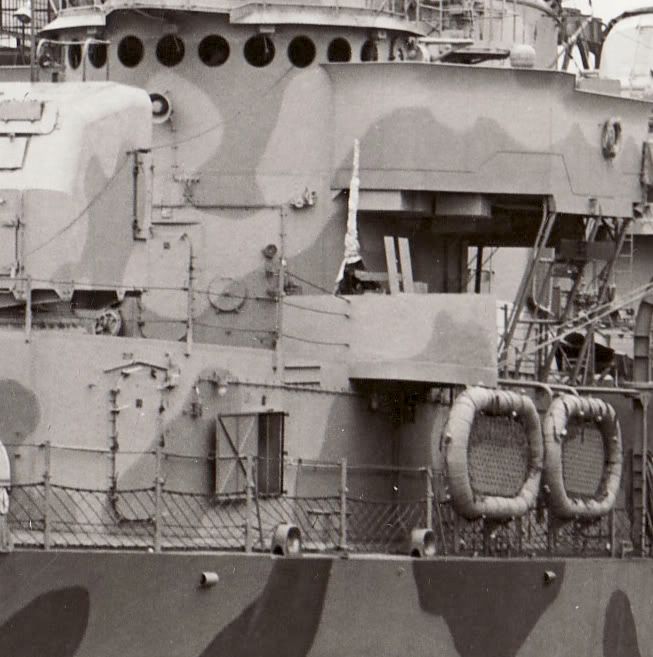
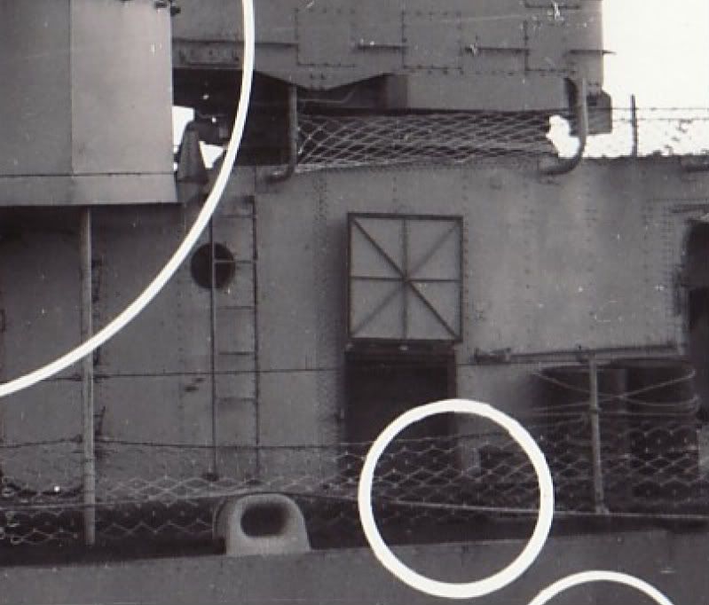
Here are some images of O'Bannon (DD-450), #1, Fletcher (DD-445), #2 and #3, and Daly (DD-519), #4, as they were completing and largely "clutter-free".
The third image shows the vent below mount 52 that had a door that could be closed if there was bad weather. I have never checked to see for sure, but I think these were common grill covered vents on all Fletchers. Locations, and styles of these apparently were changed as other changes were made in configuration (armament, etc). The fourth image shows the hatch cover over the forward vent being hinged differently from the other two ships.
-
Rotorhead
- Posts: 127
- Joined: Thu Dec 25, 2008 5:36 pm
Re: Calling all USS Fletcher class (DD) fans
Rick,
I wasn't the one asking but.............those are very good enlargements, thanks. Lots of good "info" on them. Have been saved for future use.
Regards
Steve
I wasn't the one asking but.............those are very good enlargements, thanks. Lots of good "info" on them. Have been saved for future use.
Regards
Steve
-
whaynes
- Posts: 294
- Joined: Mon Feb 27, 2006 10:32 pm
- Location: South Carolina
Re: Calling all USS Fletcher class (DD) fans
Rick, thanks. As always you have been a big help.
Walt
Walt
-
Rotorhead
- Posts: 127
- Joined: Thu Dec 25, 2008 5:36 pm
Re: Calling all USS Fletcher class (DD) fans
Hey Guys,
I'm still looking for those Fletcher condenser intakes..............or a fairly educated guess to what they look like. Looking at the Abbot's general plans, I see where they "might" have one located in each engineroom, on the opposite side of the condenser exhaust. It would "Appear" that it might be round and on the lower hull. Any ideas? Not too many photos of that area. (Tried the "Floating Drydock" route. Dry hole.)
Here is a photo of a scale Titanic hull showing square intakes:


Here is a photo showing round intake on a civilian ship in drydock:

The grill seems to be a "giveaway" that it's an intake.
Not looking for anyone to loose sleep over this but if it rings a bell in the back of your head, please let me know.
Thanks
Regards
Steve
I'm still looking for those Fletcher condenser intakes..............or a fairly educated guess to what they look like. Looking at the Abbot's general plans, I see where they "might" have one located in each engineroom, on the opposite side of the condenser exhaust. It would "Appear" that it might be round and on the lower hull. Any ideas? Not too many photos of that area. (Tried the "Floating Drydock" route. Dry hole.)
Here is a photo of a scale Titanic hull showing square intakes:
Here is a photo showing round intake on a civilian ship in drydock:
The grill seems to be a "giveaway" that it's an intake.
Not looking for anyone to loose sleep over this but if it rings a bell in the back of your head, please let me know.
Thanks
Regards
Steve
-
Rotorhead
- Posts: 127
- Joined: Thu Dec 25, 2008 5:36 pm
Re: Calling all USS Fletcher class (DD) fans
I found photos of the USCGC Taney in drydock in 2003 undergoing mainteance as a museum piece in Baltimore, MD.

She is about the same vintage (Pearl Harbor survivor), and i believe had steam turbine engines.
Here is a photo of the Condenser Discharge being prepped for being sealed up.

Here is a photo of the Condenser Injection also being readied for sealing. From other photos of this, it appears that this "scoop" is about 1' wide and 2-3' long. I had read that once underway the intake would "self pump" as in a scoop. They say this is at Frame 45.
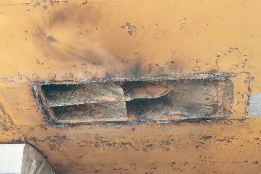
When they drydocked the ship, they planned to seal the hull. 19 openings to be welded shut.
For a helicopter guy, this is interesting stuff.
Regards
Steve
-
whaynes
- Posts: 294
- Joined: Mon Feb 27, 2006 10:32 pm
- Location: South Carolina
Re: Calling all USS Fletcher class (DD) fans
I'm currently working on the Tamiya 1/350 Fletcher-making USS LaVallette, DD 448. I have some good plans of USS O'Bannon, DD 450. LaVallette was built at Federal, O'Bannon at Bath. Were there any significant /obvious differences between ships? Would I be "safe" using the plans to add details to the model? Any replies would be appreciated .
Walt Haynes
Walt Haynes
-
Dick J

- Posts: 1990
- Joined: Mon Aug 06, 2007 6:29 pm
Re: Calling all USS Fletcher class (DD) fans
So much depends on the date for your build. As built, they were mostly the same (1.1 on O'Bannon - twin 40MM on LaVallette, etc.) prior to the post trials alterations. But later in the war, the differences depend more on in which yard they were updated rather than where built.