Calling all Fletcher-class (DD-445) fans
Moderators: BB62vet, MartinJQuinn, Timmy C, Gernot, Olaf Held, Dan K, HMAS, ModelMonkey
-
Tracy White
- Posts: 10617
- Joined: Mon Jan 10, 2005 11:02 am
- Location: EG48
- Contact:
Re: Calling all USS Fletcher class (DD) fans
That shouldn't pose any problems.
Tracy White -Researcher@Large
"Let the evidence guide the research. Do not have a preconceived agenda which will only distort the result."
-Barbara Tuchman
"Let the evidence guide the research. Do not have a preconceived agenda which will only distort the result."
-Barbara Tuchman
-
Dave Hill

- Posts: 302
- Joined: Fri Jul 13, 2007 7:20 am
- Location: "Tip-O-the Thumb" of Michigan
Re: Calling all USS Fletcher class (DD) fans
Thanks again Tracy!!!!!!!!!
Dave
Dave
"There is no problem which cannot be solved through suitable application of naval artillery."
-
whaynes

- Posts: 294
- Joined: Mon Feb 27, 2006 10:32 pm
- Location: South Carolina
Re: Calling all USS Fletcher class (DD) fans
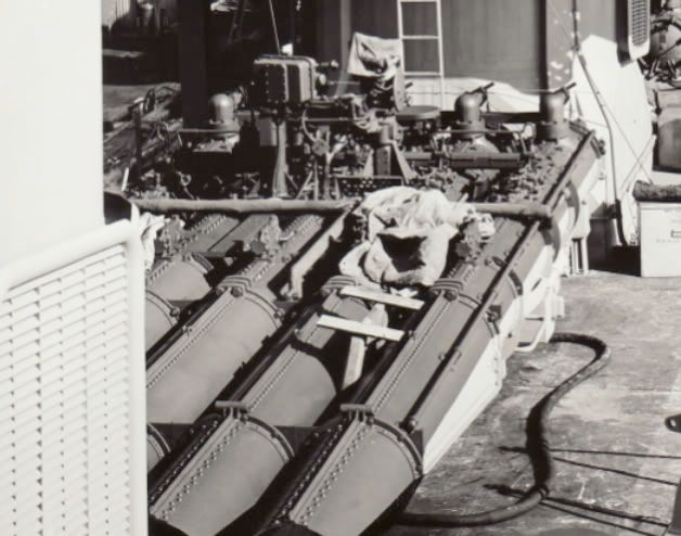
Back to LaVallette in Measure 22. Would the torpedo tubes be overall deck blue, or would the undersides be haze gray? Thanks, Walt
-
Rick E Davis
- Posts: 3871
- Joined: Thu May 29, 2008 8:02 pm
Re: Calling all USS Fletcher class (DD) fans
Walt,
This photo is on Navsource. But, this is a close-crop from a scan I did at NARA.
La Vallette (DD-448) on 9 October 1942.
This photo is on Navsource. But, this is a close-crop from a scan I did at NARA.
La Vallette (DD-448) on 9 October 1942.
-
whaynes
- Posts: 294
- Joined: Mon Feb 27, 2006 10:32 pm
- Location: South Carolina
Re: Calling all USS Fletcher class (DD) fans
Thanks, Rick. Looks like a two-tone job. Walt
-
Rotorhead

- Posts: 127
- Joined: Thu Dec 25, 2008 5:36 pm
USS Cassin Young Sonar Dome
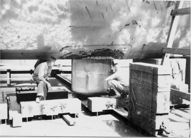
I have a photo of the Fletcher class USS Cassin Young DD-793 in drydock during 1979-80 time period. That sonar dome looks to be square on centerline? According to the plans that I have (of the ealy fletchers), it sits just slightly to the right of the keel.
Is this something done later in life post war, or was that a mod later in the build cycle. I believe she was launched in 1943.
Regards
Steve
Is this something done later in life post war, or was that a mod later in the build cycle. I believe she was launched in 1943.
Regards
Steve
-
bwross11

- Posts: 257
- Joined: Tue Nov 01, 2005 8:19 am
- Location: Medford, OR
Re: Calling all USS Fletcher class (DD) fans
Steve,
As I understand it, the sonar was offset so that the keel beam wouldn't be broken. The connections and electronics would have com up out of the dome just to the side of the keel beam. That's how it was explained to me by an old sonar tech; will be interesting to see if anyone else has a better explanation.
best,
Bruce
Bruce
OSC USN-Ret

Currently on the building ways:
1/144 USS Stevens DD-479
1/144 USS Cook Inlet AVP-36
1/144 USS Walke DD-416
1/144 USS Preble DDG-46
OSC USN-Ret
Currently on the building ways:
1/144 USS Stevens DD-479
1/144 USS Cook Inlet AVP-36
1/144 USS Walke DD-416
1/144 USS Preble DDG-46
-
Rotorhead
- Posts: 127
- Joined: Thu Dec 25, 2008 5:36 pm
Re: Calling all USS Fletcher class (DD) fans
Bruce..........I buy what your saying and from the plans I've seen, the sea chest is right smack dab up against the keel but not THROUGH the keel. These photos do not agree with what I've seen, planwise. Unless of course it's not retractable. Hence my questions.
Here is a War years photo of a Fletcher's dome. I observe that it's not the same. The Cassin Youngs 1979 dome and the one here do not look the same. Do I need glasses?
Regards
Steve
Here is a War years photo of a Fletcher's dome. I observe that it's not the same. The Cassin Youngs 1979 dome and the one here do not look the same. Do I need glasses?
Regards
Steve
-
Rick E Davis
- Posts: 3871
- Joined: Thu May 29, 2008 8:02 pm
Re: Calling all USS Fletcher class (DD) fans
The WWII Sonar and dome were different from what upgraded equipment was installed sometime in the 1950's (I don't know when). It appears that the dome was larger and mounted on the centerline ... BUT I bet that the sonar equipment didn't go through the even then.
The actual plan was to install TWO different sonars on the Fletchers. But, because sonar equipment was in short supply, needed for install on DE's, the suite was reduced to one set.
I think I have mentioned this before, but sonar must have been very sensitive subject in WWII. I have found very FEW photos of the domes/dome area during the war.
-
Rotorhead
- Posts: 127
- Joined: Thu Dec 25, 2008 5:36 pm
Re: Calling all USS Fletcher class (DD) fans
OK, all of that seems reasonable Rick. It would "appear" then that the newer dome is not retractable as was the original. I too would agree that going through the keel makes no sense.
Regards
Steve
Regards
Steve
-
Rick E Davis
- Posts: 3871
- Joined: Thu May 29, 2008 8:02 pm
Re: Calling all USS Fletcher class (DD) fans
It is doubtful that the original sonar "Dome" was retractable. I have been told it wasn't and if the photos I ran across one time (but didn't scan) of the sonar dome on one of the early Benson-Gleaves being sheared off in a collision are typical, seems to be true. The sonar equipment inside the dome was retractable for service, protection, and calibration from what I have been told. I learned more about sonar on the Fletchers (and Benson-Gleaves) than I knew a year ago ... which was next to nothing. I finally got Friedman's "Naval Radar" (at a hefty price) and "Naval Weapons" (at a very good price) books from the early 1980's and they have been a great source of information ... but, can be lacking in photos/drawings to illustrate what he is talking about for some equipment.
-
Rotorhead
- Posts: 127
- Joined: Thu Dec 25, 2008 5:36 pm
Re: Calling all USS Fletcher class (DD) fans
Thanks Rick for clearing that up for me....
I must have been dreaming. I sure thought the first version was retractable.
Regards
Steve
I must have been dreaming. I sure thought the first version was retractable.
Regards
Steve
-
Rotorhead
- Posts: 127
- Joined: Thu Dec 25, 2008 5:36 pm
Re: Calling all USS Fletcher class (DD) fans
Rick,
I still am leaning towards a retractable Sonar Dome on the early Fletchers. I'm still researching it but at first blush this picture of the equipment i believe is on the ship, shows a retractable unit.
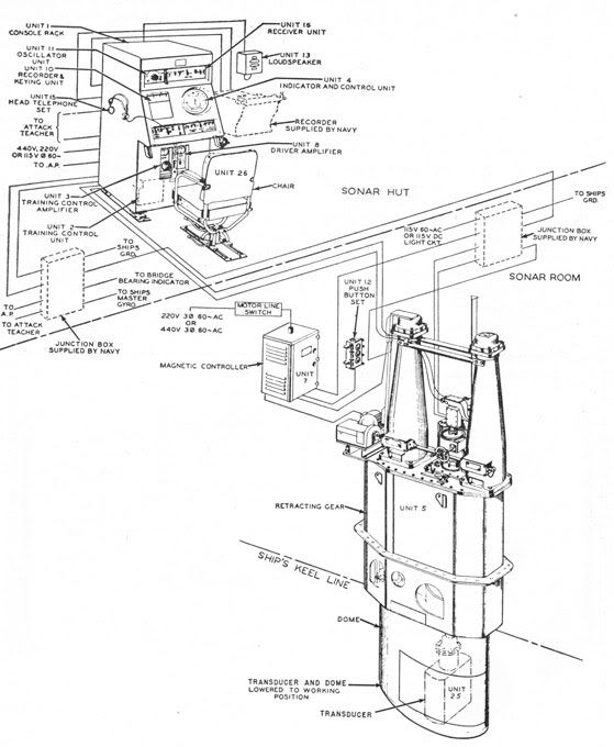
Now for my purposes of building a model..............this doesn't amount to a hill of beans. My dome will be down. I thought that was the purpose of the sea chest to provide an opening to raise and lower. Other wise it would just need a small opening for the cabling.
From the HNSA website:
"The transducer itself is mounted in a sea chest and the transducer and its hoisting units are raised and lowered inside this chest. When in the raised position, the sound dome seals off the sea chest so that water cannot enter the ship if the top of the chest were removed. Sealing off the chest in this manner permits installation, removal and servicing of the transducer and its training mechanism while the ship is at sea or in port. All other units of the system are accessible from the interior of the ship."
From the USS Slater website which used a slightly smaller version of the QJB sonar system:
Quote
DOME
the retracted position, the dome protruded three inches below the keel and was 45 inches (3 � feet) below the keel when extended. A two horsepower motor was required to raise and lower the dome with a provision to do it manually. A set of indicator lamps in the Sonar office indicated the position of the dome -- red was for the working position, green was for housed and red/green for any intermediate state. In the housed position, the dome, the raft, and the oscillator were drawn up to the top of the trunk. The top of the raft butted up against a seating ring under the top of the trunk, thus making a watertight joint. This allowed the portable cover to be unbolted, in the event that either of the oscillators had to be changed. The procedure would only work if the dome was undamaged.
The Staybrite window of the dome, was aligned with the face of the oscillator so sound waves could be transmitted and received in a 360 degree arc in 5 degree steps. Staybrite was secured over a ribbed section of heavy cast metal and this ribbing is what produced the window effect.
Maximum design speed for the dome was 25 knots. When retracting or extending the dome, it was necessary to check the voltage of the mains supply. In a 220 volt mains' system, the voltage could not drop below 180 volts. If it did, the contactor in the control board could fail to operate thus causing the dome to bump against the end stops and cause damage.
The dome was normally housed for any of the following conditions: when working cables; when working bottom lines; when entering or leaving harbor; when steaming into a heavy sea; if cessation of Sonar operations could be tolerated; and finally, when navigating in shoal water and Sonar is not required for navigation.
Unquote
I'm just curious. Building this kit has got me "looking"...............
Regards
Steve
I still am leaning towards a retractable Sonar Dome on the early Fletchers. I'm still researching it but at first blush this picture of the equipment i believe is on the ship, shows a retractable unit.
Now for my purposes of building a model..............this doesn't amount to a hill of beans. My dome will be down. I thought that was the purpose of the sea chest to provide an opening to raise and lower. Other wise it would just need a small opening for the cabling.
From the HNSA website:
"The transducer itself is mounted in a sea chest and the transducer and its hoisting units are raised and lowered inside this chest. When in the raised position, the sound dome seals off the sea chest so that water cannot enter the ship if the top of the chest were removed. Sealing off the chest in this manner permits installation, removal and servicing of the transducer and its training mechanism while the ship is at sea or in port. All other units of the system are accessible from the interior of the ship."
From the USS Slater website which used a slightly smaller version of the QJB sonar system:
Quote
DOME
the retracted position, the dome protruded three inches below the keel and was 45 inches (3 � feet) below the keel when extended. A two horsepower motor was required to raise and lower the dome with a provision to do it manually. A set of indicator lamps in the Sonar office indicated the position of the dome -- red was for the working position, green was for housed and red/green for any intermediate state. In the housed position, the dome, the raft, and the oscillator were drawn up to the top of the trunk. The top of the raft butted up against a seating ring under the top of the trunk, thus making a watertight joint. This allowed the portable cover to be unbolted, in the event that either of the oscillators had to be changed. The procedure would only work if the dome was undamaged.
The Staybrite window of the dome, was aligned with the face of the oscillator so sound waves could be transmitted and received in a 360 degree arc in 5 degree steps. Staybrite was secured over a ribbed section of heavy cast metal and this ribbing is what produced the window effect.
Maximum design speed for the dome was 25 knots. When retracting or extending the dome, it was necessary to check the voltage of the mains supply. In a 220 volt mains' system, the voltage could not drop below 180 volts. If it did, the contactor in the control board could fail to operate thus causing the dome to bump against the end stops and cause damage.
The dome was normally housed for any of the following conditions: when working cables; when working bottom lines; when entering or leaving harbor; when steaming into a heavy sea; if cessation of Sonar operations could be tolerated; and finally, when navigating in shoal water and Sonar is not required for navigation.
Unquote
I'm just curious. Building this kit has got me "looking"...............
Regards
Steve
-
Rick E Davis
- Posts: 3871
- Joined: Thu May 29, 2008 8:02 pm
Re: Calling all USS Fletcher class (DD) fans
I'm going to say it again ... I'm no expert on sonar!!! I have read so many versions of retractable verse fixed ... I don't know which is correct. I had read that the sonar dome used on DE's WAS retractable ... a guy who served on DE's in the 1950-60's said they weren't. I do know that the transducer retracted and that required the large sea chest due to the size of the unit. The BIW drawings seem to indicate a sonar dome bigger than the sea chest opening. I have come to believe that is the version of the story that HNSA gives. The first time I went looking for the sonar locations on the Fletchers in the BIW Engineering drawings, I found the TWO locations, but had no idea for a long time as to which one was used and which was "plated-over". On top of it, there were several sonars used in WWII, so some of the confusion many center on talking about different units. You really want to go nuts ... there was a calibration source that was extended out of the hull to "ping" the sonar ... I have never found where it was. 
If you figure this out ... write a book ... I could use it. 


If you figure this out ... write a book ... I could use it.
-
Rotorhead
- Posts: 127
- Joined: Thu Dec 25, 2008 5:36 pm
Re: Calling all USS Fletcher class (DD) fans
Hey Rick,
Looking at old stuff and not having the operators manual always presents problems!
I have one "feeler" still out and active, so I'll let you know. I have a friend that was the Head Snipe on a just ended war DE. I'll ask him in a week.........not that he'd know, hes too busy making sure he doesnt go DIW.
Since my "model" doesn't have power...........I think I'll just leave mine down.
BTW I'm just a helicopter pilot...........just makes me have to ask "how's that work?" all the time
Regards
Steve
-
Rotorhead
- Posts: 127
- Joined: Thu Dec 25, 2008 5:36 pm
Re: Calling all USS Fletcher class (DD) fans
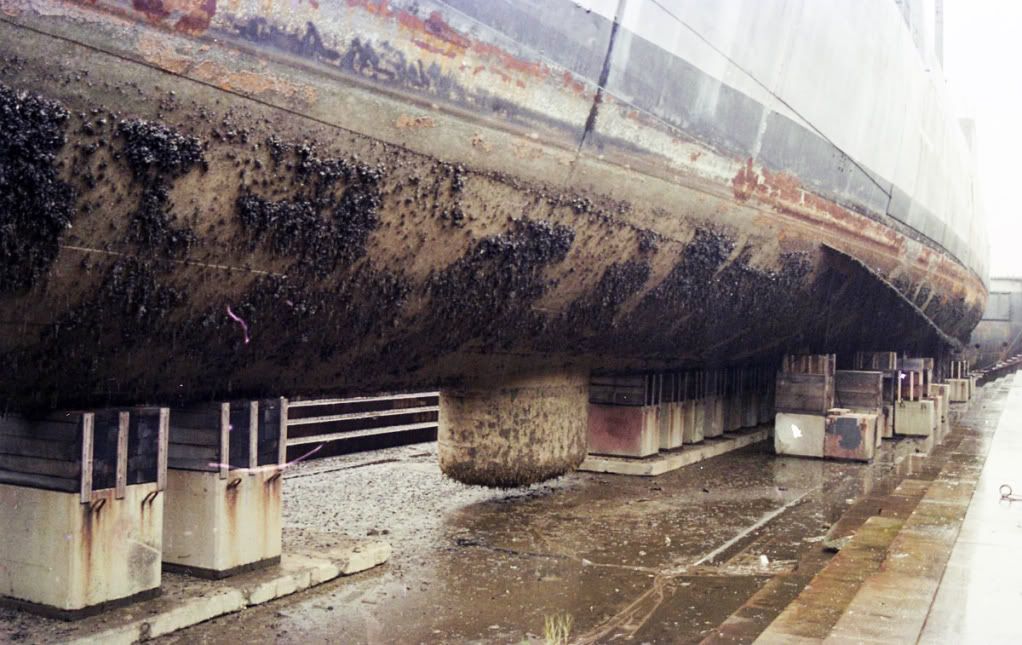
Here are a few photos that I got from the National Park Service, Boston National Historical Park. Since I'm building the Fletcher, I thought they were interesting.
USS Cassin Young DD 793 in a drydock period 1979-80, Boston.
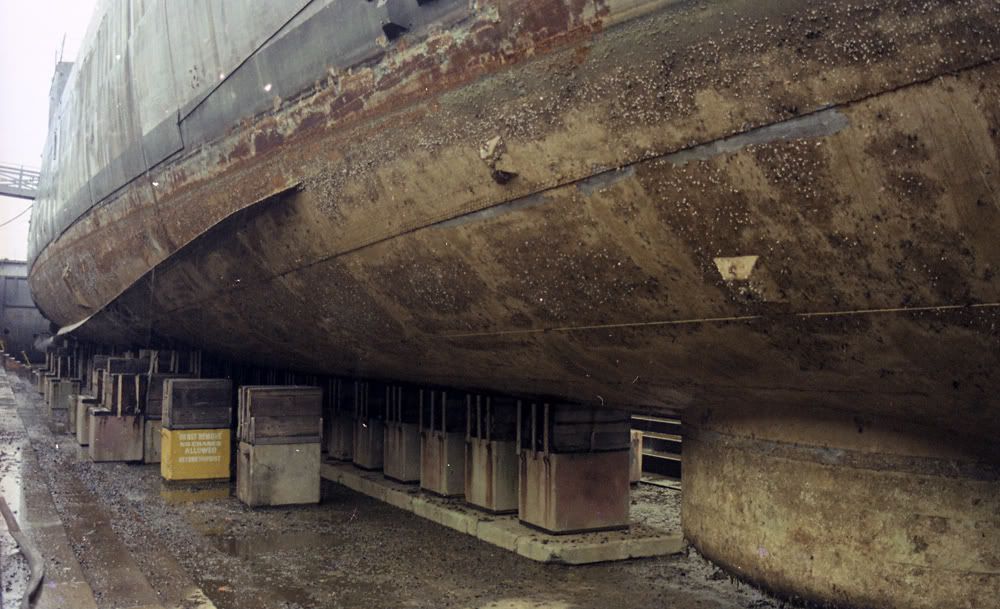
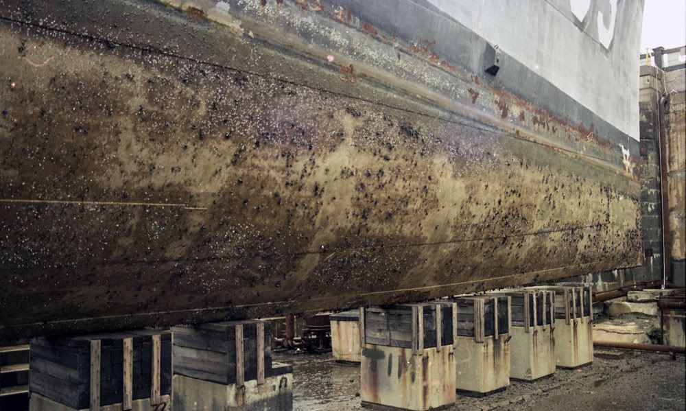
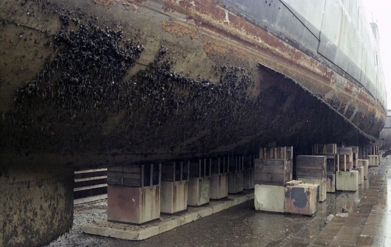

Regards
Steve
USS Cassin Young DD 793 in a drydock period 1979-80, Boston.
Regards
Steve
-
sixman
- Posts: 87
- Joined: Fri Dec 19, 2008 10:41 am
Re: Calling all USS Fletcher class (DD) fans
Since both Trumpeter and Tamiya produce Fletcher class destroyers in 1/350 have any rumors been around about Dragon making one also? From what I have read about the existing kits, there is room for improvemnet.
-
Rick E Davis
- Posts: 3871
- Joined: Thu May 29, 2008 8:02 pm
Re: Calling all USS Fletcher class (DD) fans
Sixman,
There have been all kinds of rumors (and expressed desires by modelers) about what DML will produce in 1/350 scale. I would guess that a Fletcher kit would be low on the DML priority list given that Tamiya and Trumpeter (faults or not) already have 1/350 scale kits available (and could easily undercut the price of any DML kit release) and that Revell-Germany recently released a 1/144 scale kit of the earliest Fletcher configuration. So far, DML has selected subjects not done by anyone before in plastic mold kit format.
I too would like to see a new Fletcher kit available, one done in such away to allow for multiple configurations to be built without a lot of surgery. I just don't think it will happen very soon.
-
sixman
- Posts: 87
- Joined: Fri Dec 19, 2008 10:41 am
Re: Calling all USS Fletcher class (DD) fans
Is there a review poseted anywhere on the L'Arsenal USS Sullivans upgrade kit (KC 350-03). The L'Arsenal site has a .jpg of the PE and a list on the resin included, but no .jpgs of the resin.
Has anyone used this to make a late-war suqare bridge destroyer based on the Trumpeter Sullivans kit or a late-war based on Tamiya's Flecther?
Has anyone used this to make a late-war suqare bridge destroyer based on the Trumpeter Sullivans kit or a late-war based on Tamiya's Flecther?
-
Timmy C

- Posts: 12437
- Joined: Mon Jan 10, 2005 6:00 pm
- Location: Ottawa, Canada
Re: Calling all USS Fletcher class (DD) fans
Yes, review is here: http://www.modelwarships.com/reviews/mi ... rsenal.htm
De quoi s'agit-il?