Hi Joe, and any other USS Balao class fans out there!
My thoughts of building USS Batfish (SS-310) sometime in the future went on Fast-Forward when I stopped by the “Muskogee War Memorial” (
http://www.ussbatfish.com/). I arrived right at closing time, and didn’t want to be rushed on the tour, so I didn’t get aboard her. I did pick up a brochure and had a good talk with the curator, who informed me that although they did not have plans for Batfish, plans for USS Pampanito (SS-383), another Balao class submarine, were available on-line. When I returned home, I quickly found the site and the plans (
http://www.maritime.org/tech/drawings/index.htm).
I have recently become interested in using AutoCad to make 3-D models. My first attempt at it was a 1/144 scale USS Greenling (SSN-614), a Permit class submarine that a friend of mine was on in the early 70’s. The first draft was recently “printed” on an SLA 3D printer, and I only received it this week. I haven’t started building it yet.
I am really excited about how it turned out, and this first draft was without the detailing that I included on the second draft, which I hope to get printed sometime in the near future.
In the meantime, I got interested in Batfish because it is located in Muskogee and I am in that area quite often. When I first found their website, I was intrigued by the shape and thought that it would provide a greater challenge than the circular hull of Greenling. When I then discovered the plans, I decided to try to build her.
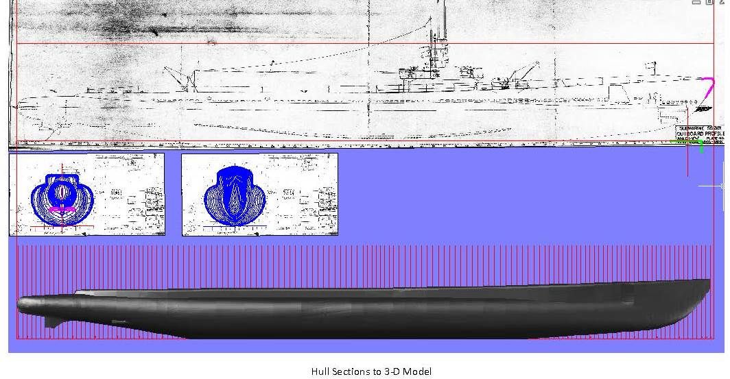
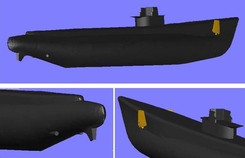
I started by importing the plan drawings into AutoCad and scaling them to the proper size. I then traced the hull half-sections (or Frames) from the “Body Plan – Outer Hull” plan sheet, using polylines. I then mirrored and joined the polylines to form the various sections. The image below shows the stern and bow sections.
Each Frame is numbered and the spacing of the frames is provided on both the “Body Plan – Outer Hull” and “Outboard Profile-Plate No. 3”plan sheets. Using the base line, I copied the Frames to their respective locations on the profile, rotated them 90o, and then lofted them.
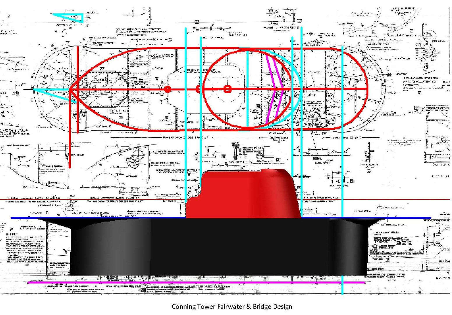
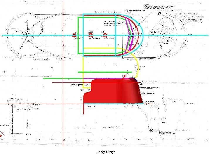
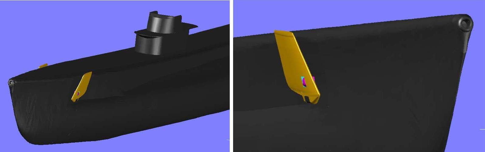
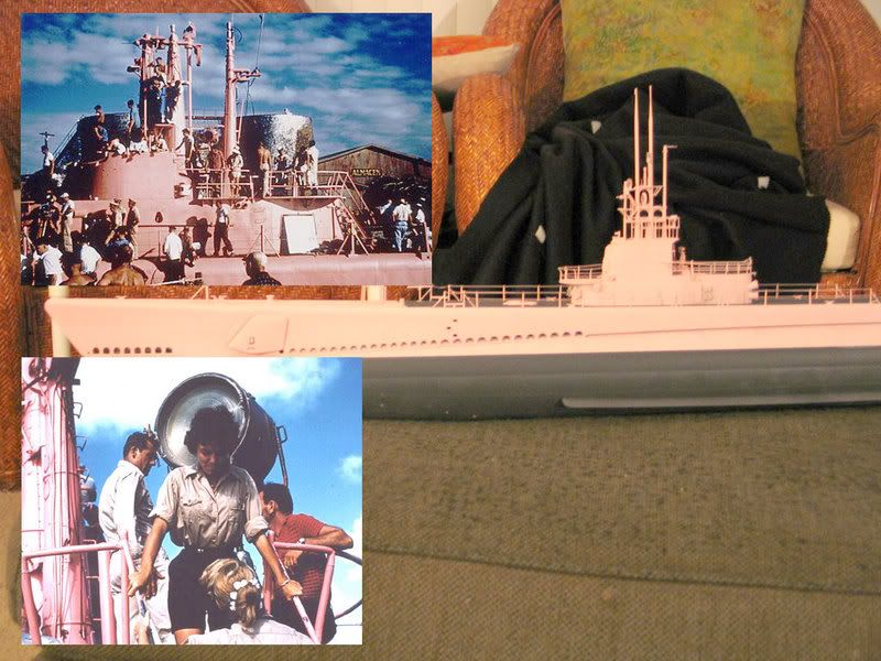
The Conning Tower was made using the “Conning Tower Fairwater & Bridge, Elevations & Plans” sheet. The bridge was made using a combination of this sheet and the “Conning Tower Fairwater & Bridge – Molded Lines & Offsets” plan sheet. The completed assembly was then copied to the correct location on the hull.
The last items completed thus far were the bow planes, which were created using the “Bow Diving Gear Plane Details” sheet and pictures of Batfish. The pictures were required because the configuration in the pictures was slightly different than the one on the plans.
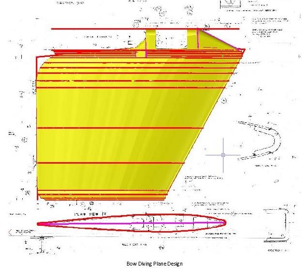
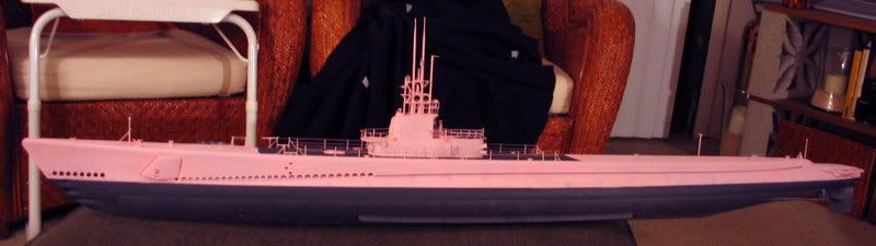
Below are some images of the ship to date. The bow plane is a separate piece and thus is colored orange. Also, I am uncertain about the upper hull attachment point, so at present it is still detached and colored magenta.

For a first cut, I like it, although I suspect that there will be changes after I get to tour the sub herself.


 Because the conning tower is Gato class, couldn't I simply build this Revell 1-220 kit straight into the USS Gato ?

