Thank you for your words Gianluigi

, I will answer you in parts:
Ramaja wrote:
The object named "red n4" doesn't seems to me to differ too much: IMO it's rather a matter of how light hits them but there are some sort of new vent hole added which were not there in older pics, unless they were covered with some sort of porthole shutter. I really have no guess about what they were for.
Seems to me there is glass at these holes, may be they used these bulges to install some kind of device, but I dont have a idea about it was.
Ramaja wrote:
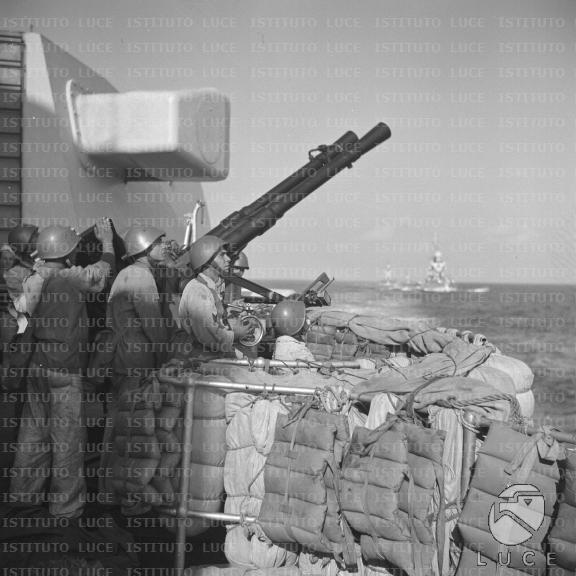
The side platform were changed indeed. The unknown device "red n2" in IMO the rear view of the light deflector close up you have posted in a picture above.
I'm not sure if its the search light we see at rear funnel platform. I have another picture from this area and seems to me search light is at a soo much low position to appears there.

And seems to me too there's no space at rear funnel platform to have the crew member we see near the object in the 1st picture. Initially I prefer not to do soo much importance to this object without other evidences.

Ramaja wrote:
The funnel slot you have created has the correct size, except it should end a bit higher from the base but that's easily fixed.
I'll check it with my references.
Ramaja wrote:
The funnel caps you rebuilt are fantastic: just check the last pics you posted on my own thread: at least on the forward one, there seems to be some sort of "ridge" on the top of the funnel cap, something not shaped and going upward, on which the catwalk railing is fixed. it should not take much effort to reproduce that feature anyway
Yes, I observed it too at Jane's picture, but I can't see it in other pictures. I know there's a tuck there, may be it combined with the top grille created a optical illusion. I'll check it latter too to have a conclusion.

Ramaja wrote:
As Allan point's out, there is a structure inside the forward funnel that puzzles me: most of the ships I've seen so far have internal divisions which reflect the number of heater to which they are connected, but this doesn't seems to be the case; it looks like a metal foil welded to the starboard side of the funnel in order to ad support for the rail cover at the top of the funnel cover, as if it was too thin to properly sustain the weight of a man during ordinary maintenance. I have no pics of the rear one interior.
Yes, I think it too, but I have no references to do it properly. Now I have no idea what I can do there.
Ramaja wrote:
I'll wait to see how you get those curved parapet in place before start changing further the shape of the platforms on the rear structure anyway the plasticard idea is good but I can't imagine how you will shape them with the upper rail curved outward. Since those kind of parapets are pretty common worldwide I wonder how other modeller have solved the problems created by over scaling or bad shape in their kits. I'm looking around and all ideas are welcome.
I'm not sure I understand you correctly, but my idea about it is:
- At 1 & 2 positions there are no curved parapet to be represented.


- But at 3, 4, 5 and 6 there are something like this.

- For 1 & 2, I see no problems, but for 3, 4, 5 and 6 I understand is impossible to curve a bended plasticard without damage it.
- I sketched the idea I have now in mind, and I think may be it has a chance to be winner. Please see my sketch like a lateral profile view.

My idea is to glue a triangular thin plasticard piece (in red) at a top from a plasticard stripe (in blue). Then sand it until the green line before curving the stripe .It's the 1st time I'll do it in this size and in soo much curved pieces and I have no idea if it will run well. But it's the only I idea I have for it now.
Ramaja wrote:
Since we are building our ship at the same time and trying to share what we have available I wonder if there is a way to create some sort of single reference thread from our own in order to offer visitors a less fragmented and better understandable soulce of information on how to solve the problems posed by this Hobbyboss kit.
If it doesn't bother you we could ask Jim Bauman what can be done about
Yes, I had think about it too, we're reuniting here a lot of research about this ship and this kit that may be util to other modellers too. And may be Jim has some way to link our posts to the Zara Class Thread at CAF. To me there's no problem to ask Jim about if it's possible to do it.
Best Regards,
Ricardo