The Ship Model Forum

The Ship Modelers Source
It is currently Sun May 11, 2025 4:53 pm

All times are UTC - 6 hours [ DST ]


Post new topic Reply to topic  [ 151 posts ]  Go to page Previous  1, 2, 3, 4, 5 ... 8  Next
Author Message
PostPosted: Mon Dec 26, 2022 7:15 am 
Offline

Joined: Fri Dec 27, 2013 6:32 pm
Posts: 531
Yesterday there was a lot of walking around, all of the ABSD sections are now primered. I used Tamiya XF18 Medium Blue for this. I suppose modulating this will get me something like the original color, because even my modeling store doesn't have the Mig colors to compare.

Image

Image

Image


Report this post
Top
 Profile  
Reply with quote  
PostPosted: Thu Dec 29, 2022 9:22 pm 
Offline

Joined: Fri Dec 27, 2013 6:32 pm
Posts: 531
Columbia's superstructure is now filling up with PE particles, after the sanding of the styrene parts. I can't place some antennas on the stacks. I also need to wait for the wooden deck to place some superimposed parts, the base needs to be painted first. And there are some differences between CL-56 and CL-62, that implies some scratchwork.
Image

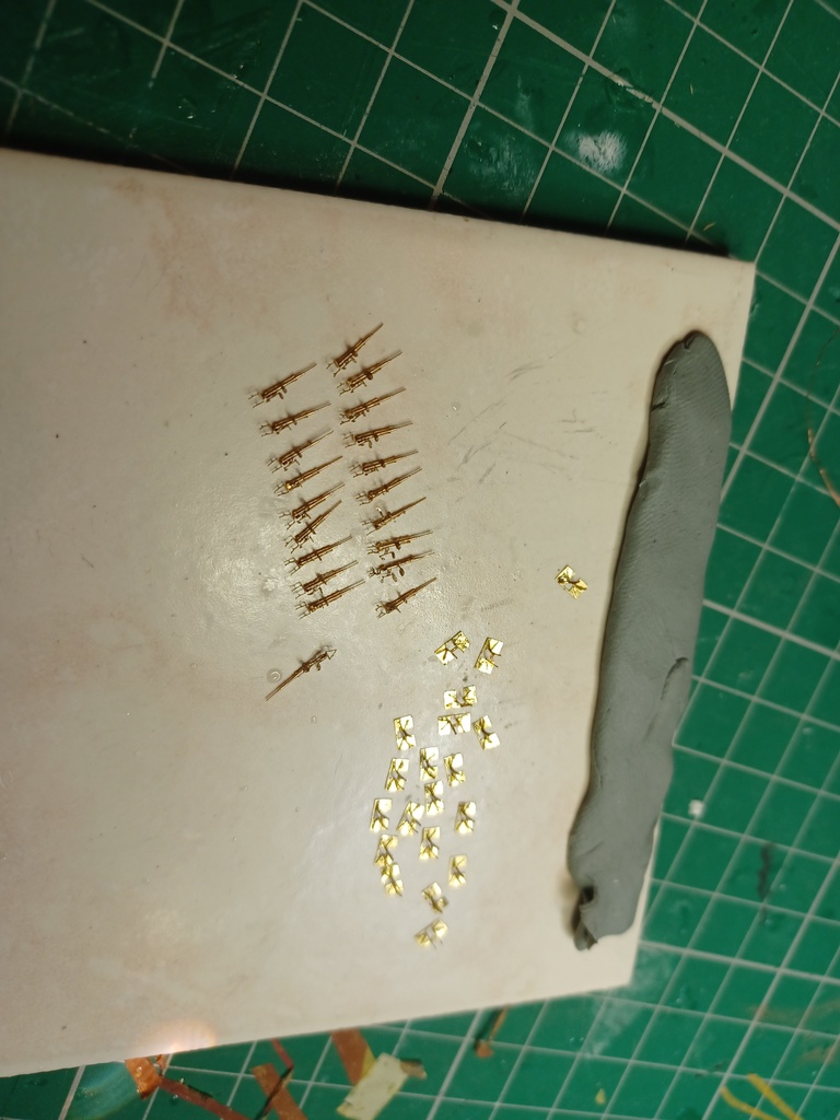
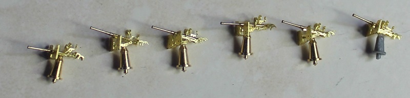
I made the secondary gun directors.

Image

The Mk51 directors each got a fragile PE part that breaks when added to the plastic.

Image

I keep the masts on hold to avoid damage.

Image

A complicated bending diagram is shown for the Mk8 primary gun control radar.

Image

The manual can be found at http://www.researcheratlarge.com/Ships/Misc/FCR-Mk8/ and you really need this drawing to understand how the part is bent. It can't be made perpendicular so it needs to be cut in half.

Image

With the Mk8 the Columbia should now be able to range in on large targets at 50.000 yards (or 143 yards in scale...).

Image

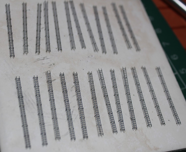
Some ladders are added to the conning tower.

Image

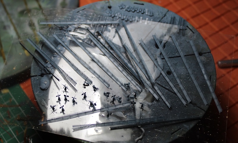
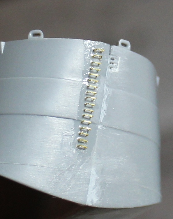
The stacks get some internal PE, but these tubes tend to crack while being removed from the sprue.

Image

The PE under the stack platform will be placed over the railing near the stack, but this is PE is wrong in the kit so I first need to find out which part will be left over in stead.

Image

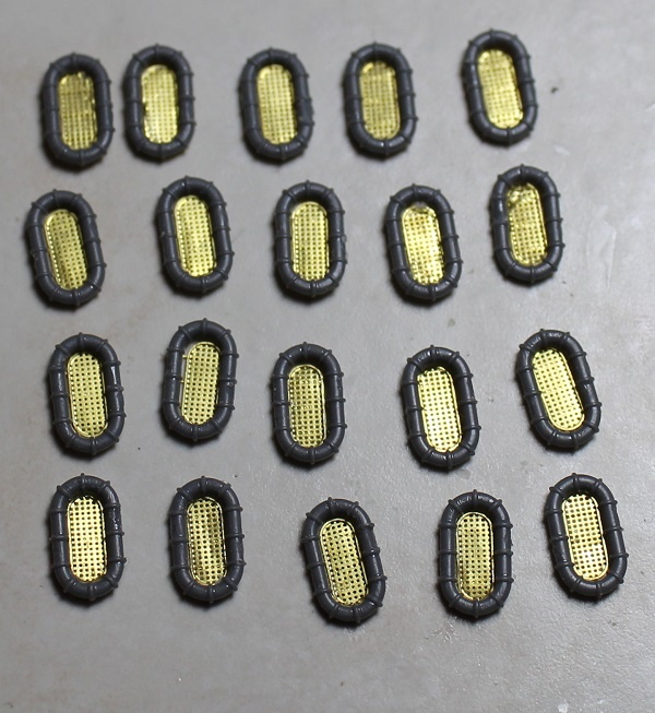
There are almost 1/10 as many small triangles as in Zuikaku. That's saying something.

Image

I still wanted to integrate these small PE grilles.

Image

Drilling small holes and connecting these while drilling.

Image

This is the aftermost part of the superstructure, after filling in the seams with putty.

Image

Now with the rangefinders on it.

Image

Strange how the mast holes don't line up. I had to correct the lower hole.

Image

Dry-fit without railing.

Image

Image

Some railing is now added, but not where the wood deck has to come.

ABSD is now shadowed with some German Gray. The small triangles keep falling off, some are now lost.

Image

Image

Image

Image

Image

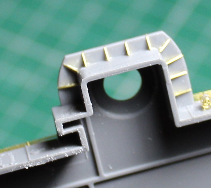
The midships barbettes are now superdetailed.

Image

Small sinkmarks are riddling these and other kit parts. Here sanding would be difficult.

Image

I was spared this by the extension kit.

Image

Even the underside is impoved.

Image

The magazine holders are a nice touch.

Image

Some are misnumbered though. Part C2 is not needed on the deck barbettes in this sprue, but in the round barbette on the cilinder.

Image

These are added and get some inclined ladders. But those are difficult to bend because of the small steps.

Image

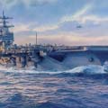
This image shows how Columbia differs from other Clevelands. The barbette after the second 5 inch gun has a rectangular base. In another topic I read the explanation:

http://www.shipmodels.info/mws_forum/viewtopic.php?f=48&t=34416&start=360

Quote:
Cleveland had two twin 40mm guns port and starboard on the O4 level of the forward superstructure just aft of the main battery Mk 34 director. It also had two twin 40mm port and starboard on the O3 level of the aft superstructure about even with the Mk 37 director. Columbia kept the two twin 40mm on the aft superstructure but the forward pair were replaced with two Quad 40mm on the O1 level just forward of midships.


Image

But on this 1945 picture, I'd say both of these look like doubles. I could be wrong and you could see double barrel pairs.

Image

At last the secondary gun director radars are added. But we denn't need the orange peel, that's 1945 Birmingham.

Image

So the long turned radar axle is replaced with a wire.


Report this post
Top
 Profile  
Reply with quote  
PostPosted: Sun Jan 01, 2023 8:41 pm 
Offline

Joined: Fri Dec 27, 2013 6:32 pm
Posts: 531
I continue to replace barbettes with scratch sheet metal.

Image

This also showed the PE capstans.

Image

Image

These barbettes still need reinforcement ribs. I can place them, but not yet the munition racks, because of the wooden deck under it.

Image

Most of these windlasses are on the superstructure, but two of them are also on that deck and are put aside.

Image

They are smaller than they look here.

Image

The kit parts for the P6-type steam catapults can be jettisoned.

Image

The PE parts look impressive but are easy to bend.

Image

Because of the riveting, glue must be used sparingly.

Image

Here most PE parts are added. The rings are surprisingly hard to centre.

Image

A dry-fit now all kitparts and the sleigh are added.

Image

The rings are a good fit on the deck.

Image

The sprues for the Kingfishers contain a peculiar node shaped like a Worms sprite. I actually still have this game on my PC. It even had a level with some WW2 airplanes as the scenery.

Image

Strange is also how you get a cockpit kitpart that is not used in the kit manual, because without clearpart it would be invisible, but in the expansion kit it is required in addition to the resin cockpit part. Did the PE canopy feature in the design of the kit but was it left out? There are a few of number errors on the last parts of fret M from the kit, like if they had to change this when they ran out of PE space.

Image

With some pushing the fuselage fits around the resin cockpit.

Image

I had to observe the symmetry of the plane.

Image

This is also important while assembling the wing floaters.

Image

Bending the canopy so it fits on the fuselage is quite easy because of internal etch lines.

Image

I will replace the antenna wire with Uschi rigging thread. The pylon should not be in the middle of the cowling as displayed. The props that were mislabeled are prepared, but will be painted before assembly.

Image

In this testshot the catapults can not yet bear the weight of the planes. In the picture of Columbia in the ABSD there are no planes visible, while a wing should be. I did find a shot of a Cleveland in a stateside drydock with the planes still on it, so it should be possible to use them.


Report this post
Top
 Profile  
Reply with quote  
PostPosted: Sat Jan 07, 2023 8:05 pm 
Offline

Joined: Fri Dec 27, 2013 6:32 pm
Posts: 531
Image

The crane was halfway through the assembly process, when I saw the frame was reversed. It had to be undone and repeated the other side. It took me not so long to correct.

Image

As fiddly as it looked flat, when bent it's sturdy.

Image

Photo etch cabling is removed from the camwheels, it will look better with thread.

Image

I'm revising the front quad 40mm barbette, as Columbia looked like this in 1944.

Image

I used styrene for this, the result would be better with thin sheet metal but it's easier to fit in smaller styrene parts with Tamiya Extra Thin.

Image

It's mirrored on the starboard side.

Image

The underside of the superstructure is then adapted to the new shape.

Image

Holes are filled up.

Image

The base plate is rising to 25mm to fit the PVC frame around it.

Image

Then I finally fixed the ABSD with the screwing system I provided. The water parts between the pontoons would get locked in and had to be added before the rest of the diorama water. Weathering of the sidewalls is not necessary because a grating is placed over the sidewalls of the pontoons, mostly obscuring the details. The positioning of the pontoons was even harder than I imagined, because I found deviations in the bore holes of the wooden plate. In the end I found little of the threaded holes I made in the model and only used half of the bolts I had provided. But this will still be abundant for keeping the ABSD down.

Image

Because this is still going on, the outro today is about the 40mm AA guns.

Image

There are 4 quad mounts in the Cleveland set. Columbia would have had only two according to the "all Cleveland Cruiser fans" topic, but at least according to Popular Mechanics this was not always the case, so I will be using the four quads.

Image

The text above this picture confirms this is Columbia's front quad 40mm barbette.

Image

Another picture shows Columbia is still in the original setup, only a camo is used. The barbette is not changed yet and it already had a quad 40mm.

Image

These parts all come from the upgrade.

Image

Why qoing through the ordeal of drilling in the stiff resin to insert barrel pins? I simply clipped these and butt glued the barrels on.

Image

Soon the 20mm guns can be built, afther the aiming devices and seats. This is going smoothly. It will not be the last 40mm builds for this project, though, some are projected for the freighter model.


Report this post
Top
 Profile  
Reply with quote  
PostPosted: Mon Jan 09, 2023 3:22 pm 
Offline

Joined: Fri Dec 27, 2013 6:32 pm
Posts: 531
ABSD-1 was now firmly screwed to the base, but it had a noticeable seam between part 3 and four. To get a contact between the barges, 3 had to be removed. Wall parts came off soon, with so little glue connecting them to the deck.

Image

Yanking the barges losse proved harder than expected. By pushing a steel plate under them, I could pry them loose but the water paste only gave with a resounding pop. This shook apart one of the photo etch booths on the walls, so this had to be completely assembled again.

Image

Image

The wall on part two also sheared off the tower, while its internal ladder kept hold.

Image

The bore holes were lengthened and some of the paste was chiseled off.

Image

Quite soon all was restored. Another deviaton was found in the middle, but here the ship will cover most of it and it would not be prudent to advance to there.

Image

All this heaving coused more of the catwalk supports to get lost. Even with my spars I still need to retrieve 4. Now some pics with the ship on the dock.

Image

Image

Image

Image

Image

Image

Image

Image

Image

One detail is the fit of the walls, most are still quite loose. This will soon be remedied with extra glue. I would advise anybody to drill through all the connection points and insert metal rods to get a better fit, as it can not be guranteed that the walls ar perfectly perpendicular with the weak connection to the deck.

Image

A problem associated with Columbia was to find a decent SC-2 radar antenna. I looked first at Eduard as this is easiest to acquire here in EU. While it signaled to contain one such antenna, it apparently had a different type with a round dish. WEM (set 35111) and Tom's Modelworks (3505) do have it, but ordering these would be extremely uneconomical. But I had already used this antenna on Princeton. Was it possible that I unknowingly already had the solution on hand?

Image

In this fine Pontos set, two of these antennas are included. I investigated this strange phenomenon and apparently the pylon under the antenna could have two different dimensions. Luckily it was decided to duplicate also the antenna in the set, while it's never needed twice in one kit. So Columbia can now be completely built.

Image


Report this post
Top
 Profile  
Reply with quote  
PostPosted: Wed Jan 11, 2023 8:37 am 
Offline
User avatar

Joined: Mon Jan 10, 2005 5:30 pm
Posts: 5556
Location: Nr Southampton England
Phew!! that was quite the read!!-- what-a-lot-of-work !!

The ship placed in the drydock does look a treat;
were you able( if so how) to straighten the warped resin deck sections.>?

BRAVO ! :thumbs_up_1: :thumbs_up_1: :thumbs_up_1:

_________________
....I buy them at three times the speed I build 'em.... will I live long enough to empty my stash...?
http://www.modelshipgallery.com/gallery ... index.html

IPMS UK SIG (special interest group) www.finewaterline.com


Report this post
Top
 Profile  
Reply with quote  
PostPosted: Fri Jan 13, 2023 9:34 pm 
Offline

Joined: Fri Dec 27, 2013 6:32 pm
Posts: 531
Thanks for the comment, Jim. I didn't solve the dock (styrene) deck curve problem because it's not very visible and pushing the center up would pose the risk of popping the decks out of the hulls. If you mean the resin deck of the tow boat, that was straightened with a frying pan heated on an induction plate.

Image

I bought this but I am not sure if it is necessary for the freighter. Trumpeter sure makes nice gun sets now, they might even top the Very Fire ones.

Image

The Pontos CS-2 radar is built but I have to change the mast under it.

Image

Therefore the Very Fire crow's nest needs to be clipped and the top prolonged with a tube.

Image

This has been done and the yardarms are taken out of the crow's nest and put back on the mast.

Image

The ABSD walls are now straightened and the parts connected with CA glue, giving the cranes a straight ride.

Image

But I still found a gap between dock section 4 and 5. This I wanted to eliminate to not make the dock seem broken.

Image

I flipped the entire diorama on its head, supporting the water part with two steel scaffolds. Then I sawed it through carefully, not causing any damage to the model.

Image

A thin strip is ground from the plate.

Image

This allows the dock to fit together perfectly. The seam will only need repair on the right, as the freighter will cover it on the left side.

Image

The sawing was possible because here was no support under the plate, but now I had to make this to avoid weakness at the seam.

Image

The plastic frames are glued with PVC glue and a spanner.

Image

A large seam at one edge is caused by correcting a small angle between dock elements, this simply needs some filling. Then 60 large PE parts were cleande up.

Image

It's best to prefabricate the catwalks, now the inner walls are harder to reach.

Image

A lot of connectors had to be filed away, often 11 per catwalk part.


Report this post
Top
 Profile  
Reply with quote  
PostPosted: Sat Jan 14, 2023 5:35 am 
Offline
User avatar

Joined: Mon Jan 10, 2005 5:30 pm
Posts: 5556
Location: Nr Southampton England
Most excellent--and very brave (!! ) - solution to the docks gap issue-- a few nervous moments I can imagine..!

Ref the bowed deck--I did not notice it on the docks--so you are right it wont be noticeable ! :thumbs_up_1:
I did mean the tug deck

did you have the deck section naked in the frying pan or in water.?

I have had similar issues in the past with 'old tech' resin hulls and cured them by oven heat and screwing to stainless steel base plates

maybe your method is safer?
Best wishes
JB

_________________
....I buy them at three times the speed I build 'em.... will I live long enough to empty my stash...?
http://www.modelshipgallery.com/gallery ... index.html

IPMS UK SIG (special interest group) www.finewaterline.com


Report this post
Top
 Profile  
Reply with quote  
PostPosted: Sat Jan 14, 2023 9:07 am 
Offline

Joined: Fri Dec 27, 2013 6:32 pm
Posts: 531
Jim, there was no water, only the resin part pressed on the heated cooking pan bottom. Because the warping was the strongest in the middle, that part was taking most of the heat and was softened more. Only a slight deformation there shows that there ever was warping now, and this will be covered by the surf.

The most enerving part about the dio flipping were the two bridge parts that can turn on their hinges by their gravity point moving. You always have to check not to crush them.

The warping on the dock deck is transverse, it can be seen in the middle of some of the walls where a seam is showing where you can see light shining through the wall. An extra bulwark in the hull could prevent this, and give a lot more glue surface for the walls.


Report this post
Top
 Profile  
Reply with quote  
PostPosted: Tue Jan 17, 2023 6:59 pm 
Offline

Joined: Fri Dec 27, 2013 6:32 pm
Posts: 531
Image

The pointy file that is used on al this PE.

Image

The Master Models Oerlikons that were built for the ABSD this weekend.

Image

Part of this PE was excruciatingly thin to fold.

Image

Barrels and splintershields are ready, but one gun set too early and had to be dissolved in acetone.

Image

Image

20 to go, more to come later when the ships are provided with the Very Fire Oerlikons and some more Masters.

Image

Some extra PE is integrated in the superstructure. All triangles under the platforms are set now.

Image

Image

Image

Image


Report this post
Top
 Profile  
Reply with quote  
PostPosted: Wed Jan 18, 2023 3:04 am 
Offline

Joined: Tue Feb 06, 2007 10:24 am
Posts: 2567
Location: Belgium
You're working very hard Steven; that's excellent progress! :thumbs_up_1: :thumbs_up_1: :thumbs_up_1:


Report this post
Top
 Profile  
Reply with quote  
PostPosted: Wed Jan 18, 2023 4:10 am 
Offline
User avatar

Joined: Fri Jan 16, 2015 1:12 pm
Posts: 74
Location: Alkmaar, The Netherlands
Great work! Currently building the 1/350 VeryFire USS Salem wíth the detailset myself, I know how much and sometimes tedious work it is! But very rewarding!
Cheers, Walter


Report this post
Top
 Profile  
Reply with quote  
PostPosted: Thu Jan 19, 2023 6:47 pm 
Offline

Joined: Fri Dec 27, 2013 6:32 pm
Posts: 531
Thank you, my fellow SIG members!

Image

PE is ready to be painted on the underside.

Image

The covers between the deck parts are removed now and the rest is reapplied to paint the catwalk topside.

Image

The catwalks are highlighted with light blue and the guns are painted individually. I expect to build some for the ship this weekend and then all of these and the ones for the D-Day dio can be painted gunmetal.

Image

The covers are glued between the decks and on the walls. Now nothing can fall between anymore, some small parts always disappeared like that.

Image

Walkways between the sections are added an the large ladder is now touching the deck.

Image

Image

The catwalks are finished, finally connecting all those brittle triangle parts.


Report this post
Top
 Profile  
Reply with quote  
PostPosted: Thu Jan 19, 2023 7:59 pm 
Online

Joined: Tue Jan 11, 2005 10:56 am
Posts: 8798
Location: New York City
Wow. An incredible amount of detail work. Everything's looking great.


Report this post
Top
 Profile  
Reply with quote  
PostPosted: Sat Jan 21, 2023 9:39 am 
Offline

Joined: Sat Sep 17, 2005 9:19 am
Posts: 1548
Very nice catwalks Steven. How did you keep them straight?


Report this post
Top
 Profile  
Reply with quote  
PostPosted: Sat Jan 21, 2023 8:41 pm 
Offline

Joined: Fri Dec 27, 2013 6:32 pm
Posts: 531
Thanks, Dan and Pieter. The catwalks are keeping straight because of the L-shaped cross-section with the front vertical girder needing to be plied downward. Like that, they also screen some of the deviation the support triangles can have from the mesh underside.

Again 6 Oerlikons are produced, this time for Columbia. The Cleveland upgrade has Pe and barrels for 9 guns, but it only has 5 turned bases. According to plan, I need at least 6 and the bases are larger than these of the Master Models set I have left.

Image

Maybe this is because you get the choice between the turned base and the lightweight PE one. But Birmingham pictures show the massive base.

Image

I expect to see the same in early 1944 Columbia. The splintershield type is consistent with the Columbia ABSD pictures, though, differing with the 1942 Birmingham pic just shown.

Image

So this is as before, but just a tiny bit less fragile than Master Models.

Image

Barrels and shield subassemblies created.

Image

The guns are completed after the elevation wheel is added:

Image

Image

Image

In the upgrade also 3 Carley Float sprues without bottoms were offered.

Image

While 24 floats were cast, only 20 can be completed with PE webbing.

Image

Aligning this PE is almost impossible.

Image

Image

To facilitate this, the floats were left in the sprue while the PE was glued onto them.

Image

To clean the burrs, a stepped milling tool was needed.

Image

Some of these could come in handy for the other ships.

Image


Report this post
Top
 Profile  
Reply with quote  
PostPosted: Fri Jan 27, 2023 1:18 pm 
Offline

Joined: Fri Dec 27, 2013 6:32 pm
Posts: 531
On each ABSD wall a scale is added. These I had painted before removal from the sheet. That way the back side would be covered before assembly.

Image

They are a bit tricky to apply to the wall, there are no glue edges, only small pins.

Image

After these another batch will be fixed from the catwalks to the deck, but I want to paint that first.

Image

This picture shows Birmingham with some impressive bomb damage. You can also discern scales going down the middle and one smoke installation left at port. These will now be detailed.

Image

The Veryfire drill aide is fixed to the stern and a fine drill is inserted in the Dremel.

Image

There was a fracture but I succeeded in making all the necessary holes. I also polished the stern seam.

Image

The steps had inserts, so this was very easy to glue.

Image

Quite a lot of subparts went in to the smoke screen tanks.

Image

After assembly.

Image

These are fixed to the deck, but contrary to Birmingham in the last picture I believe Columbia had circular gun tubs.

Image

Here this part of the ship can be seen from close by at an early 1943 stage, with a gun under a tarp. A chock can be seen in front of it, this is missing in the model.


Report this post
Top
 Profile  
Reply with quote  
PostPosted: Sat Jan 28, 2023 10:37 am 
Online

Joined: Tue Jan 11, 2005 10:56 am
Posts: 8798
Location: New York City
A lot of great progress there.


Report this post
Top
 Profile  
Reply with quote  
PostPosted: Sat Jan 28, 2023 7:10 pm 
Offline

Joined: Fri Dec 27, 2013 6:32 pm
Posts: 531
Thanks, Dan. Today we look at the freighter. I did not decide on the ship's name but used a picture of SS Lyon, a Mediterranean theatre ship, for comparison: http://www.navsource.org/archives/09/22/22071.htm. The bridge details were very much like the Revell Hawaii Pilot and it was clear what had to be changed.

Image

So that means the railings the sunscreen and the superstructure supprts had to be removed. Look at the AA positions on the flying bridge and the kingposts.

Image

Removal of the railings with an Airwaves micro saw.

Image

The visible part of the deck with the planking had the pin marks.

Image

I will be using the Cleveland doors and windows to correct the freighter split window arrangements. The steering cabin windscreen with its overscale partitions was removed.

Image

First all is glued and clamped together. I also added a metal strip to the front row of windows so the wall could be sanded smooth.


Report this post
Top
 Profile  
Reply with quote  
PostPosted: Fri Feb 03, 2023 7:02 pm 
Offline

Joined: Fri Dec 27, 2013 6:32 pm
Posts: 531
Image

The railing is removed from the deck and any traces of it are polished away. The bringe support beams are removed because they are out of scale and location. The bitts are retained but need to be detailed with a flange.

Image

Fitting the deck to the hull is a meticulous job, it should be flush. This is working out well nonwithstanding the age of this mold.

Image

The bridge is also attached. I need about 70 PE portholes with eyebrows but I got only 50 from the Veryfire set. Also I will need additional ladders.

Image

The anchor chains can be much improved with some PE I left over from Princeton. The holes need to be drilled open.

Image

The PE is added but the cargo hold should still be furbished a bit.

Image

All winches had some components replaced with sprue parts. That made the cable hubs round.

Image

With some of the watertight doors assembled, the tapering walls were very evident. All of these were chiseled to a right angle.

Image

Image

Then the doors could return..


Report this post
Top
 Profile  
Reply with quote  
Display posts from previous:  Sort by  
Post new topic Reply to topic  [ 151 posts ]  Go to page Previous  1, 2, 3, 4, 5 ... 8  Next

All times are UTC - 6 hours [ DST ]


Who is online

Users browsing this forum: Timothyo and 40 guests


You can post new topics in this forum
You can reply to topics in this forum
You cannot edit your posts in this forum
You cannot delete your posts in this forum
You cannot post attachments in this forum

Jump to:  
Powered by phpBB® Forum Software © phpBB Group