UPDATE 23
Hi All!
It has been a while since my last update, but that is not because I have not been making progress. Rather, it is because it got to onerous maintaining two logs, and the other Forum I have been posting to, the SubCommittee Forum
(
http://s181686668.onlinehome.us/phpBB3/ ... 35&t=11272), allows posting multiple pix at one time rather than having to put them in one by one, which is a lot faster. Anyway, the AutoCad model is completed, so I thought I would post the final results.
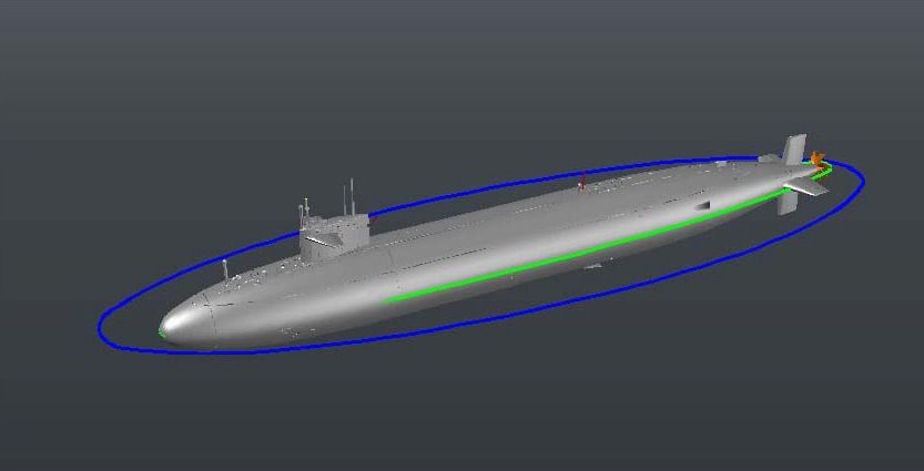
The first image shows the port side view, as well as the front and aft views.
Attachment:
 Wip-023-01.jpg [ 127.02 KiB | Viewed 1630 times ]
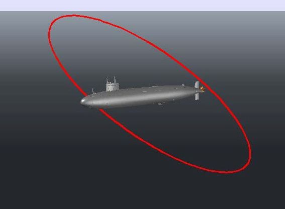
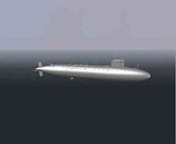
The next two images show the starboard side from oblique angles.
Attachment:
 Wip-023-02.jpg [ 64.65 KiB | Viewed 1630 times ]
Attachment:
 Wip-023-03.jpg [ 66.64 KiB | Viewed 1630 times ]
Here is a close up image of the forward escape trunk area. You can clearly see the sonar fairing, the retractable cleats, as well as other detailing.
Attachment:
 Wip-023-04.jpg [ 40.11 KiB | Viewed 1630 times ]
In the next image some of the detailing on the port side of the sail can be seen, including, but not limited to the bow-light/jack staff attachment (the staff itself is not part of the model), the hull numbers, the ladders, the port side navigation light and the open bridge closure and windshield (another good thing about the plastic being clear).
Attachment:
 Wip-023-05.jpg [ 47.46 KiB | Viewed 1630 times ]
The next image shows the forward section of the ship on the starboard side. The sail including the search and attack periscopes (aft), the BRA-21 Antenna, the BRD-6 ECM, the top of the BRA-21 antenna and snorkel inductor (fwd) are visible on top of the sail. All but the top of the BRA-21 antenna are separate parts. The bow light/portable jack staff is seen on the bow. Barely discernible aft of the sonar dome line are some of the bow draft numbers.
Attachment:
 Wip-023-06.jpg [ 46.92 KiB | Viewed 1630 times ]
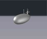
An image showing the bottom of the ship, as seen from the front, is shown next. You can see the some of the MBT flood hole baffles, the rod meter (not included in the model) and the Secondary Propulsion Motor (SPM).
Attachment:
 Wip-023-07.jpg [ 81.63 KiB | Viewed 1630 times ]
The SPM is shown in more detail in the next image. Additional MBT flood hole baffles may be seen as well. The hole at the top of the picture is one of the mounting holes.
Attachment:
 Wip-023-08.jpg [ 43.44 KiB | Viewed 1630 times ]
As you can see from the images, if you have been following this build, the final product is a bit more elaborate than I originally imagined. The final part diagram is shown below.
Attachment:
 Wip-023-09.jpg [ 146.2 KiB | Viewed 1630 times ]
As you can see my original concept of a dozen parts expanded a wee bit to 27 parts. Designing the model in AutoCad was so much fun that I just kept going. I figured that even if my buddy can’t make all of the parts, the fun of doing it made it worth it. As for the SPM assembly, that was probably a little bit of an overkill, because I doubt if it will ever be retracted, but making it retractable was beneficial for three reasons. First, if it was fixed to the hull, it would be a protrusion begging to be broken off, so making it a separate part eliminated this potential. Second, I think it is a cool feature (if it works), even if it is never used. Third, it was friggin’ fun to do!
The final image shows the metal parts template. It is shown actual size and enlarged for better viewing. As you can see, it also got a bit more elaborate than I originally thought, but not by much.
Attachment:
 Wip-023-10.jpg [ 123.3 KiB | Viewed 1630 times ]
Now that the design has been completed, the DWG (drawing) files have been converted to STL (stereolithography) files and sent to my buddy, the waiting begins.
How long the wait will be, I do not know. My buddy leaves for China Thursday and will be gone 2 weeks. Since I would be extremely surprised if he got them made before he leaves, I expect the wait will be 3 weeks or so. What happens next? I have no idea.
To begin with, I’m not sure my buddy has had time to look at the latest design, so I’m not sure that he knows that it has expanded from 12 to 27 parts. Though I think the chances are small, he may not be able, or willing, to do this many parts. If that happens, I will have to rethink the design.
Otherwise, it all depends on how the parts turn out. The test parts, even though they fit together well and had sufficient detail to show that the moveable planes was possible, were a different design and did not have any detailing, so I really have no idea how they will turn out. Under the best of circumstances, I am not naïve enough to think that Murphy (as in Murphy’s Law) won’t make an appearance somewhere. With 27 pieces, it seems unlikely that I won’t have an issue with one or more of them. The question is how many there will be. And how hard they will be to fix.
The metal too, is still a big unknown that we haven’t talked that much about. He told me where to get the metal, but I haven’t started looking into that yet, and even though I have completed the template layout, we still haven’t talked about what format he needs it in. In my limited experience with laser cutters, 2D line drawings were used and I imagine that is the case with the one he has. I also do not know if the laser he has can etch as well as cut by simply reducing the beam strength, or if it can only cut.
So there are still many unknowns to come. I’ll keep you posted when something changes.
CHEERS!!!