The Ship Model Forum

The Ship Modelers Source
It is currently Sun May 11, 2025 4:56 pm

All times are UTC - 6 hours [ DST ]


Post new topic Reply to topic  [ 151 posts ]  Go to page Previous  1, 2, 3, 4, 5, 6 ... 8  Next
Author Message
PostPosted: Sun Feb 05, 2023 6:36 am 
Offline

Joined: Fri Dec 27, 2013 6:32 pm
Posts: 531
The portholes are now applied with an engraving needle. Some glue on the needle will run in the ring and then it can be pulled back with a turning move.

Image

The ABSD deck was instructed to be painted gunship grey, but this will rust quickly.

Image

Some cardboard was cut to cover the wall but the tubes would remain exposed. I was in no mood to mask all these, I'll just repaint them later.

Image

The interior of the ABSD was soon completely rusty.

Image

Image

Image

Image

Image

For the outside, also 2 cardboard pieces were used. One for the wall with a small hole for the jacking point:

Image

And one to protect the hull. This left the railing exposed, maybe a drybrush will be applied to correct that.

Image

A night and a day were used to do all of this.

Image

Image

Image

Image

The wall tops will be harder to mask.


Report this post
Top
 Profile  
Reply with quote  
PostPosted: Mon Feb 06, 2023 6:48 am 
Offline

Joined: Tue Feb 06, 2007 10:24 am
Posts: 2567
Location: Belgium
You're working hard Steven! :thumbs_up_1: :thumbs_up_1: :thumbs_up_1:

I don't envy you on the freighter... All the rest looks like a lot of fun though!


Report this post
Top
 Profile  
Reply with quote  
PostPosted: Mon Feb 13, 2023 3:25 pm 
Offline

Joined: Fri Dec 27, 2013 6:32 pm
Posts: 531
Hi Marijn, it's easy when you can switch between models, the freighter is steadily advancing but some stuff is still missing.

Image

One of the most egregious errors in the Hawaiian Pilot kit are the crossbeams on the masts. These are 200% overscale, I found this out by comparing the length with the ship's beam on pictures, a plan and the model. Also the bottom should be hollow. An Evergreen box construction with a metal bottom to drill in did the trick. The protuberances under the model's crossbeams should just be the rigging.

I don't have all components to scratch the mast itself, I'm still missing 2.8mm brass tube. Something else I procured from the Modellbaukönig.

Image

I needed something to lower the relative sending cost, hence the Pegasus kit.

Image

Trumpeter names this "Ladders and Railing 1/350".

Image

Only on closer inspection you see the inscription "Germen (sic) ladders". So German ladders be it. And a thing they also did not show, the ladders come twice. I would even need to start the second part.

Image

Removing one step, the ladders were connected to the forecastle. Ample space to add 20mm platforms on the sides.

Image

2 pairs of ladders on the bridge front.

Image

Four on the promenade deck.

Image

And at the superstructure aft, four of them. One originates from the Cleveland set and has the US handrails.

Then it's ABSD time again. On the top of the wall 100 lampposts were painted blue before. But even the top deck has to be rusty, looking at the colour video's. How to mask all of these?

Image

It doesn't work with Micro Mask. It's hardly possible to scrape it off and then the paint is gone. Because I didn't trust it, I had only tested it on 5 lamps.

Image

So I was down to tape. Not wanting to cut 100 part of it, I decided to cut 5 transposable tape cones to put over the posts. Tilting the cone permits to get around it.

Image

25 per cent done, already two hours had past.

Image

Now 50 per cent is done after 4 hours, and I strongly recommend painting before assembling the lamps...


Report this post
Top
 Profile  
Reply with quote  
PostPosted: Thu Feb 16, 2023 3:16 pm 
Offline

Joined: Fri Dec 27, 2013 6:32 pm
Posts: 531
All of the rust parts have been treated with some darker brown shade and then a lot of orange in between.

Image

Image

This will now get a gloss coat.


Report this post
Top
 Profile  
Reply with quote  
PostPosted: Sat Feb 25, 2023 8:06 pm 
Offline

Joined: Fri Dec 27, 2013 6:32 pm
Posts: 531
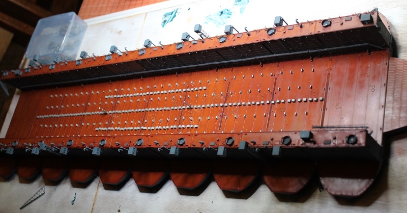
I still had to replace the ABSD extreme platform with the smaller barge you see on the pictures.

Image

Image

Some staples attached to a piece of Green Stuff styrene and the outside is made.

Image

These Normandy Rhino's show the topside texture I need.

Image

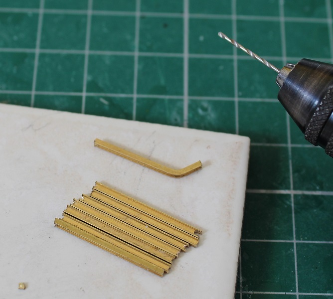
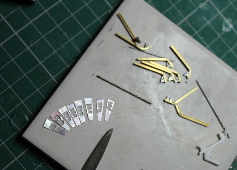
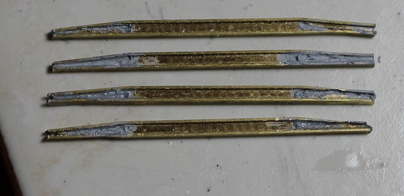
To make this out of the staples, some engraving is needed.

Image

Image

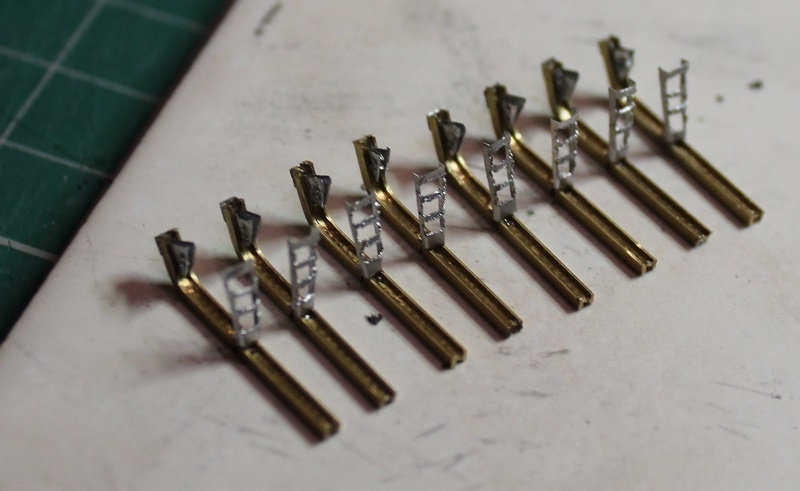
A grid is engraved and two long staples are arranged around three rows of six short ends. These are filed to the exact length.

Image

With all staples attached with some CA, more filing makes the top level out and it removes the scars on the flattened staples.

Image

Image

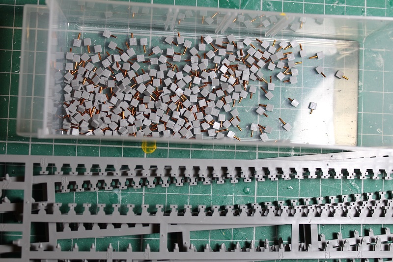
For a CL I need about 4/5 of the total number of wood blocks included in the ABSD kit, as there are two out of 10 sections that are not covered. It has more than 550, so 400 should do it. Because the ship will be connected to a lot of these blocks and I can't predict the movement of the hull on them during transport of the dio, I wanted each of the blocks to be pinned down.

Image

A 0.7mm copper pin would do the trick.

Image

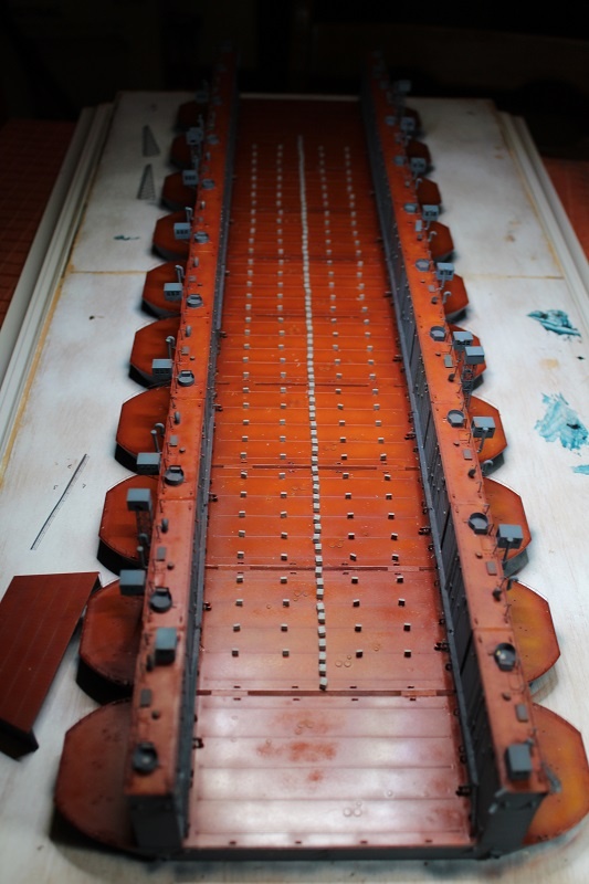
Half of the pins were added here.

Image

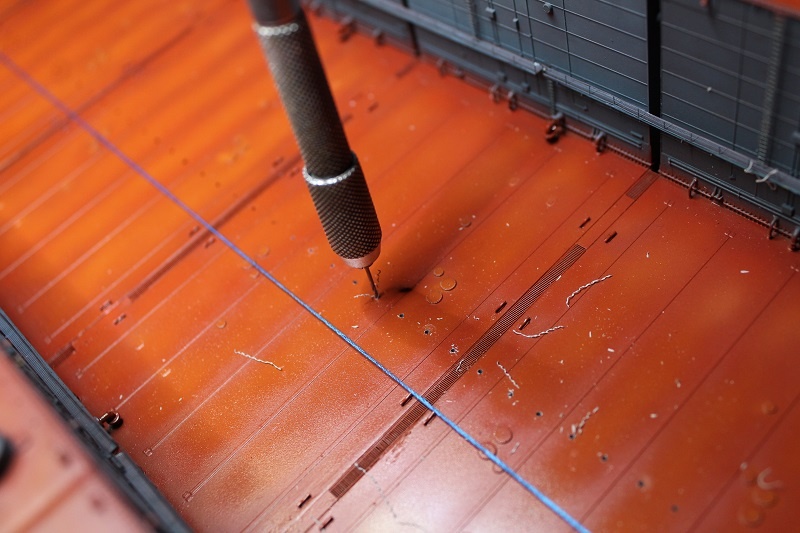
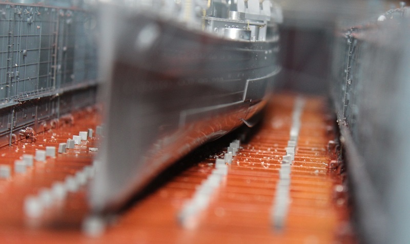
All of the pins I need are added, the removal of these blocks from the sprue is surprisingly hard. Strange how they chose to connect them sideways to the sprue, it's a lot of work to remove the burrs now. I only pinned 5 out of 8 sprues I drilled out, because I figured the outmost rows of blocks wouldn't be connected to the hull and they might be impossible to drill on the ABSD with the walls and catwalks present. Something to consider is that the blocks were not part of the construction, so the rust wash I'll do has to precede the assembly of the blocks. A few of them will get the copper thread protruding above the block into the hull. Then, with the ship fixed, the deck can finally be added to it.

Image

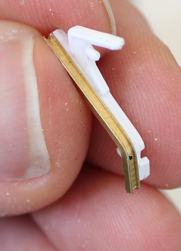
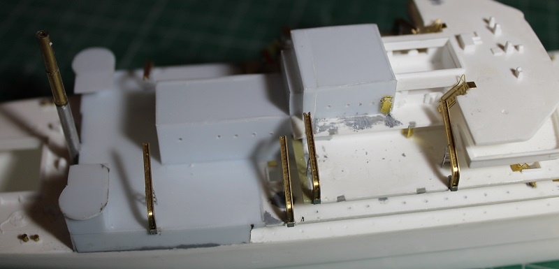
To replace the freighter mast, I decided to use the wonderful range of AK Interactive brass pipes. They offer them from 0.2mm to 3mm with an interval of 0.1mm, so I had to order a series that I did not already own from other brands. I made use of the order to get me some MAIM 1/35 oddities, for other purposes of course.

Image

Another unique feature of these pipes is the gross weight. I needed something between 2.5 and 3mm, so I ordered 2.8mm.

Image

The first two measures I cut needed a filler tube to fit them to the center, but the AK one is so thick that it fits without one.

Image

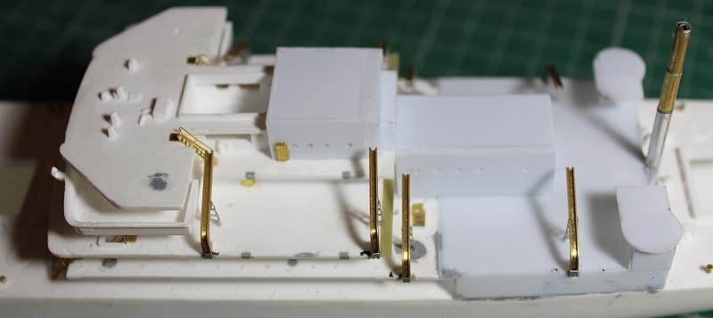
But this caused some interval in the top tube that made it sit crooked on the center tube. The stern mast is therefore sitting not so perfect.

Image

The front one is even better. It would only be improved if I had used 2.8 on 2.9 on 3mm.

Image

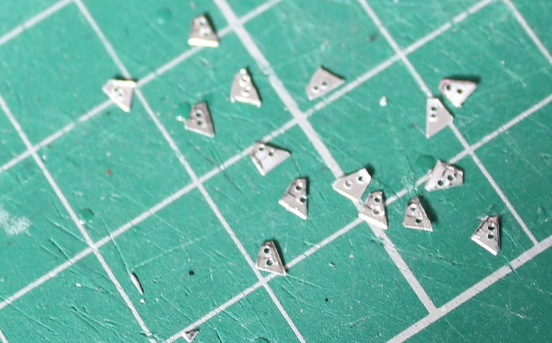
For the bow armament I had looked at the wrong pictures, checking out anterior C3 AP classes. These have a B-shaped platform.

Image

For Bayfields the right shape is rectangular with a sphere inscribed to make room for a 5 inch/38 gun. I fit the L'Arsenal gun in it, and a second one on the stern. The platform will go on the forecastle after a base is added. I'm still looking where the ladders will run in it.

Image


Report this post
Top
 Profile  
Reply with quote  
PostPosted: Sun Feb 26, 2023 2:53 am 
Offline

Joined: Fri Dec 27, 2013 6:32 pm
Posts: 531
David, these ladders will be placed when the platform is installed. My question is actually about the ladders I already put from the forecastle downwards. On this picture it's very hard to see if there is a ladder between the stacked row of carley floats and the platform base. The railing of the forecastle seems not to be interrupted on that location. The stairs could have been integrated in the base structure or they could be at the back of it. But they could just be there behind these floats. There are pictures of what seems a contemporary model of Bayfield on Navsource and there is nothing there, but it's also a bit crude in the finishing.


Report this post
Top
 Profile  
Reply with quote  
PostPosted: Sat Mar 04, 2023 8:29 pm 
Offline

Joined: Fri Dec 27, 2013 6:32 pm
Posts: 531
One of the most extensive ABSD picture sets can be found on: https://www.realwarphotos.com/#/gallery/advance-base-sectional-dock-absd/n22432/. One of these shows the berthing blocks in close detail (see attachment).

This shows that the shape of many blocks is different from what you get in the box. It seems these different blocks are combo's of 3 kit blocks. Putting the ships only on narrow blocks wouldn't make much sense, these would topple over during the berthing process.

Image

I had some spare sprues of blocks left, so I could use these to flesh the middle row of blocks. That is working a lot faster if the row is removed and added to the next one.

Image

Cutting the sprue with the cutting disk reduces stress on the glue. Some sanding is needed to remove the flash. A wire is again added.

Image

A thread is tended over the deck center. Along it the drilling annotations are made.

Image

40 holes are pre-drilled with a Dremel and resized with the pin-vise.

Image

The blocks are dry-fitted. 2 of these will be used to fix the ship.

Image

The typical Bayfield-freighter forecastle is now ready. Two barbettes for the 20mm are added.

Image

Another pair is prepared.

Image

These would only fit if I removed 2 winches and relocated these.


Attachments:
absd6.jpg
absd6.jpg [ 128.57 KiB | Viewed 802 times ]
Report this post
Top
 Profile  
Reply with quote  
PostPosted: Fri Mar 10, 2023 7:33 pm 
Offline

Joined: Fri Dec 27, 2013 6:32 pm
Posts: 531
Image

Something about the ship's profile was not right. The smoke stack shouldn't be so high above the yardarms.

Image

To make that happen, part of the stack is cut off and the lower mast parts replaced.

Image

On the ABSD, rows of small blocks are dry-fit in the drill holes.

Image

5 can be in a row on a pontoon, because they need to stand on a transverse girder.

Image

With the remainder I will make extra triple block rows.

Image

2 stainless steel pins are inserted between the keel blocks. The hull had 2 drill-trough holes on the inside.

Image

Some pics with the ship's deck dry-fit on these pins.

Image

Image

Image


Report this post
Top
 Profile  
Reply with quote  
PostPosted: Sat Mar 11, 2023 10:20 pm 
Online

Joined: Tue Jan 11, 2005 10:56 am
Posts: 8798
Location: New York City
Continued beautiful work.


Report this post
Top
 Profile  
Reply with quote  
PostPosted: Thu Mar 16, 2023 7:00 pm 
Offline

Joined: Fri Dec 27, 2013 6:32 pm
Posts: 531
Thanks, Dan, I just made 2 more rows of triple blocks from what was left in the sprue.

Image

Image

These will be painted now. In Antwerp I found brass barrels for 5 inch guns. I looks a lot better when there's a hole in the front, and they are more graceful.

Image

Image

Bayfield type ships were converted to Attack Ships (APA) and a model was made to design them: http://www.navsource.org/archives/10/03/03033a.htm . It's better than the real ship's pictures because all parts are named.

Image

The winches on the weather decks are removed.

Image

They're trimmed.

Image

They are still too thick to use.

Image

The deck will be leveled on top of these support plates.

Image

A 0.5mm styrene plate is fitted in the hole.

Image

Then a new pair of barbettes is prepaired.

Image


Report this post
Top
 Profile  
Reply with quote  
PostPosted: Fri Mar 17, 2023 2:15 am 
Offline

Joined: Mon Apr 17, 2017 2:43 am
Posts: 294
Looking great! I love the Oerlikons and the superdetailed floats!! great painting job too! :cool_1:

_________________
http://www.3xblackcats.wordpress.com


Report this post
Top
 Profile  
Reply with quote  
PostPosted: Sat Mar 18, 2023 7:10 pm 
Offline

Joined: Fri Dec 27, 2013 6:32 pm
Posts: 531
Thanks, SG1, I hope when the weathering starts, that paint will be a good base. Today we need a Navsource picture of the freighter DuPage:

Image

It shows the two port davits on a different level. Element A is a bent H- or U-profile with an end plate forming an arm. Element B is an A-shaped standard with a flange. C are triangles to anchor it to the deck, with lightening holes in them. We will make 8 of these lower units today. Next time the upper components with red letters will follow. This is a heavy beam (D) between 2 arms, a moving part E to lower the Higgins boats and F, berthing blocks.

Image

Nothing better to imitate the arms but a brass profile of 1,5 x 1 mm. Going from the Pilot to a Bayfield doubles the needed number of elements.

Image

Bending goes like this, but I should have laid flat the profile.

Image

The right shape is achieved.

Image

The profile can be broken after drilling holes in the centerplate every 21mm and making a notch.

Image

The position for the bending drill can be copied from the first part.

Image

8 done in no time.

Image

These are the holed triangles minus the tip, to weld them to the bent profile.

Image

The A-standard is made by bending in 8-fold a metal strip and then drilling through this in the pattern needed for the holes. Then it is cut out and fine-tuned with a file.

Image

After bending the sides, the standard from the pic is emerging. Still 16 welding plates will be needed.

Image

With these stands the davits are level with the triangles. The connection with the superstructure must still be cleared.


Report this post
Top
 Profile  
Reply with quote  
PostPosted: Sun Mar 19, 2023 5:03 am 
Offline

Joined: Fri Dec 27, 2013 6:32 pm
Posts: 531
Thanks for pointing things out, David. I never solder if it's not electric and even that goes wrong. I used metal because the channel had to be bent. In plastic this would have caused the outside of the I to warp at the bend point and stand open. I thought that would even occur in the brass, so I'm pleased it did not. In the model there already were indents in the deck edge where the first davits were needed, I will just repeat this at the lower deck. The only thing that remains is that the I is not an U, but half of that will be covered with element E. I do think that a U channel would crack if bent to 60 degrees, they must have welded the plates.


Report this post
Top
 Profile  
Reply with quote  
PostPosted: Sun Mar 19, 2023 6:27 am 
Offline

Joined: Fri Dec 27, 2013 6:32 pm
Posts: 531
Now there appear to be even some ships where the bottom of the U is left out, see USS Alpine.

http://www.navsource.org/archives/10/03/100309206.jpg

The upper end is not supported in other ships, though in the detail pics it seems a support is made to the kingpost.


Report this post
Top
 Profile  
Reply with quote  
PostPosted: Mon Mar 20, 2023 3:04 am 
Offline

Joined: Tue Feb 06, 2007 10:24 am
Posts: 2567
Location: Belgium
You have been busy Steven. Great work! :thumbs_up_1: :thumbs_up_1: :thumbs_up_1:


Report this post
Top
 Profile  
Reply with quote  
PostPosted: Wed Mar 22, 2023 3:27 pm 
Offline

Joined: Sat Jul 30, 2016 5:33 pm
Posts: 1932
Location: Stockholm, Sweden
This is such an inspiration for my 1/700 kit that I have in stash! Liking the contrast of colors here!

_________________
- @Shipific on IG
my gallery


Report this post
Top
 Profile  
Reply with quote  
PostPosted: Wed Mar 22, 2023 5:12 pm 
Offline
User avatar

Joined: Mon Jan 10, 2005 5:30 pm
Posts: 5556
Location: Nr Southampton England
reallyb really great woks--and there is so much of everything!!

BIG Bravo for your tenacity, perseverance and dogged refusal to compromise.

Most excellent :wave_1:

JB :thumbs_up_1: :thumbs_up_1: :thumbs_up_1:

_________________
....I buy them at three times the speed I build 'em.... will I live long enough to empty my stash...?
http://www.modelshipgallery.com/gallery ... index.html

IPMS UK SIG (special interest group) www.finewaterline.com


Report this post
Top
 Profile  
Reply with quote  
PostPosted: Fri Mar 24, 2023 8:11 pm 
Offline

Joined: Fri Dec 27, 2013 6:32 pm
Posts: 531
Thanks for the attention, Marijn, Pascalemod and Jim. It's better to persevere now and lose some time in details than building something that looked almost right. In this posting the freighter superstructure is completed before the davits can be added. For this two sidewalls are prepared.

Image

The structure after the stack is then built and the promenade deck was lengthened with a 3mm resin strip.

Image

The part that followed after this structure would intersect with two winches, so these had to be removed.

Image

The hole that was left was filled and the typical Bayfield APA housing completed. Holes were made in the deck edge for the davit arms.

Image

These are sunk partly in these holes and then fixed with CA. The holes were then filled with putty.

Image

Image

To make the heavy lifting beams some 1.5mm brass profile is used.

Image

To cut the profiles a hole was drilled and then the drill was used a s a fine saw to cut out 7mm in the centerplate on both sides.

Image

Still one part short of finishing the davits.


Report this post
Top
 Profile  
Reply with quote  
PostPosted: Sat Mar 25, 2023 5:57 am 
Offline

Joined: Mon Apr 17, 2017 2:43 am
Posts: 294
Very clever use of the drilling bit, and a new trick to learn! Thanks for sharing. Excellent progress!

_________________
http://www.3xblackcats.wordpress.com


Report this post
Top
 Profile  
Reply with quote  
PostPosted: Tue Mar 28, 2023 4:54 pm 
Offline

Joined: Fri Dec 27, 2013 6:32 pm
Posts: 531
Thanks for the comment, SG1. I used the drill again in this update to start cutting the brass. But the next parts are made from plastic.

Image

These are the arms that hold up the beam. They move by gravity in the U-channel.

Image

I made them to just clamp the beam so it would be easy to glue.

Image

Image

On both sides of the bridge a splinter shield is added.

Image

A smaller brass profile is used to reproduce the pulleys for the davits..

Image

The lower part was harder to position with everything fixed on the deck.

Image

Some changes were done to the deck house.

Image

From Ebay I won a bid of two types of Voyager Carley floats, some Flyhawk guns and directors for only 25 euros. I did have to ask to change the bid settings to international. Often some nice offers are inaccessible for foreigners. Luckily I was the only bidder.

Image


Report this post
Top
 Profile  
Reply with quote  
Display posts from previous:  Sort by  
Post new topic Reply to topic  [ 151 posts ]  Go to page Previous  1, 2, 3, 4, 5, 6 ... 8  Next

All times are UTC - 6 hours [ DST ]


Who is online

Users browsing this forum: Timothyo and 42 guests


You can post new topics in this forum
You can reply to topics in this forum
You cannot edit your posts in this forum
You cannot delete your posts in this forum
You cannot post attachments in this forum

Jump to:  
Powered by phpBB® Forum Software © phpBB Group