UPDATE 28
Greetings All! And thanks once again Nicolas.
I finally got the parts, and even though they aren’t the detailed parts I thought that they would be, it was still really cool holding them. As you know, being fellow modelers, holding something you made is a rewarding experience.
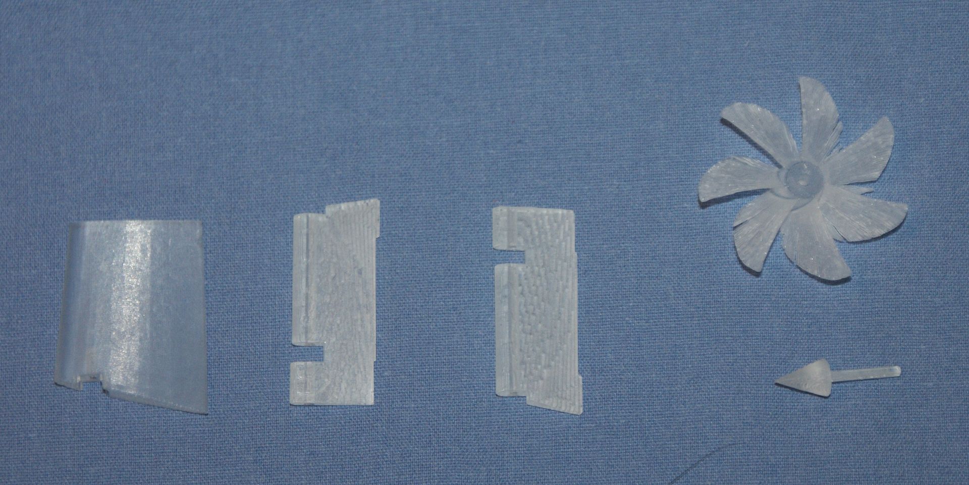
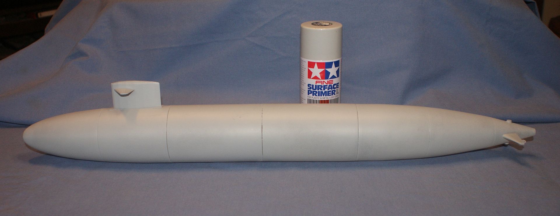
Below are pictures I took of the model. The first picture shows all of the parts.
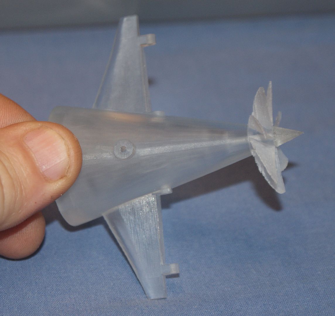
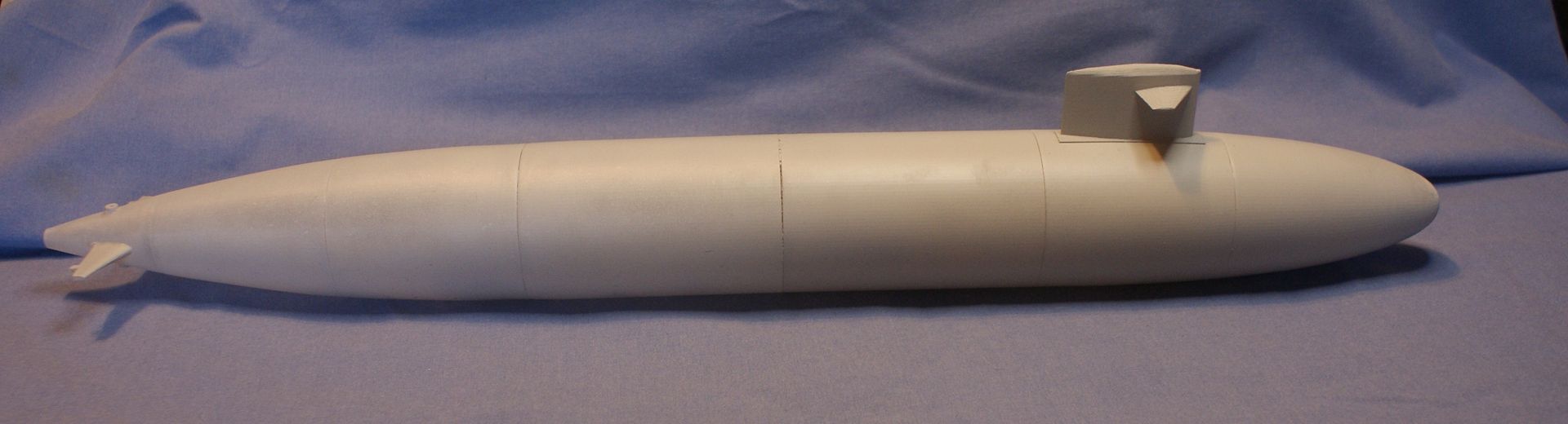
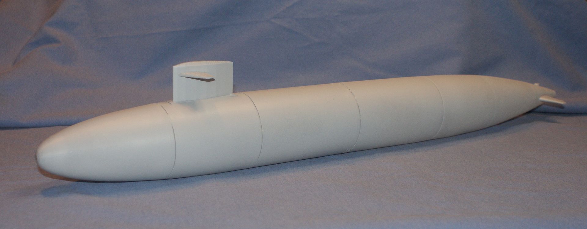
The next picture shows the first three segments. I really like the way the nose came out. I had to add several cross sections in addition to the ones on the plans to get the nicely rounded shape, and I am thrilled how it turned out. You can also clearly see the attachment point for the sail on the second piece and the alignment posts on the third piece.
The next picture shows the mid-section parts. Again you can see the alignment posts. You can also see that the alignment bar didn’t get printed on the first piece on the left. I don’t know how this happened. If you look at the part in Update 4, back on November 27, 2012, the bar is there. Unfortunately, I can’t check the AutoCad files because I moved on and long since deleted the older versions.
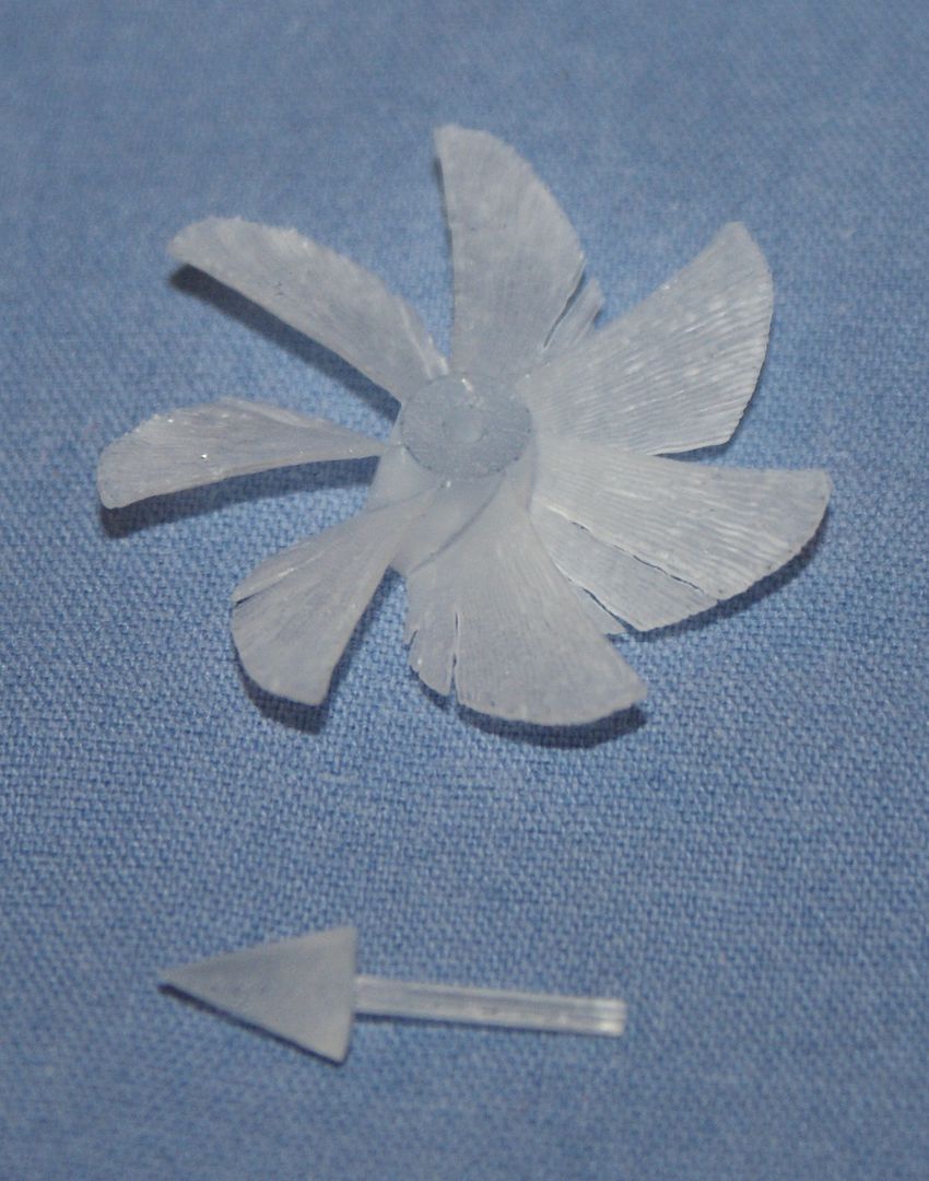
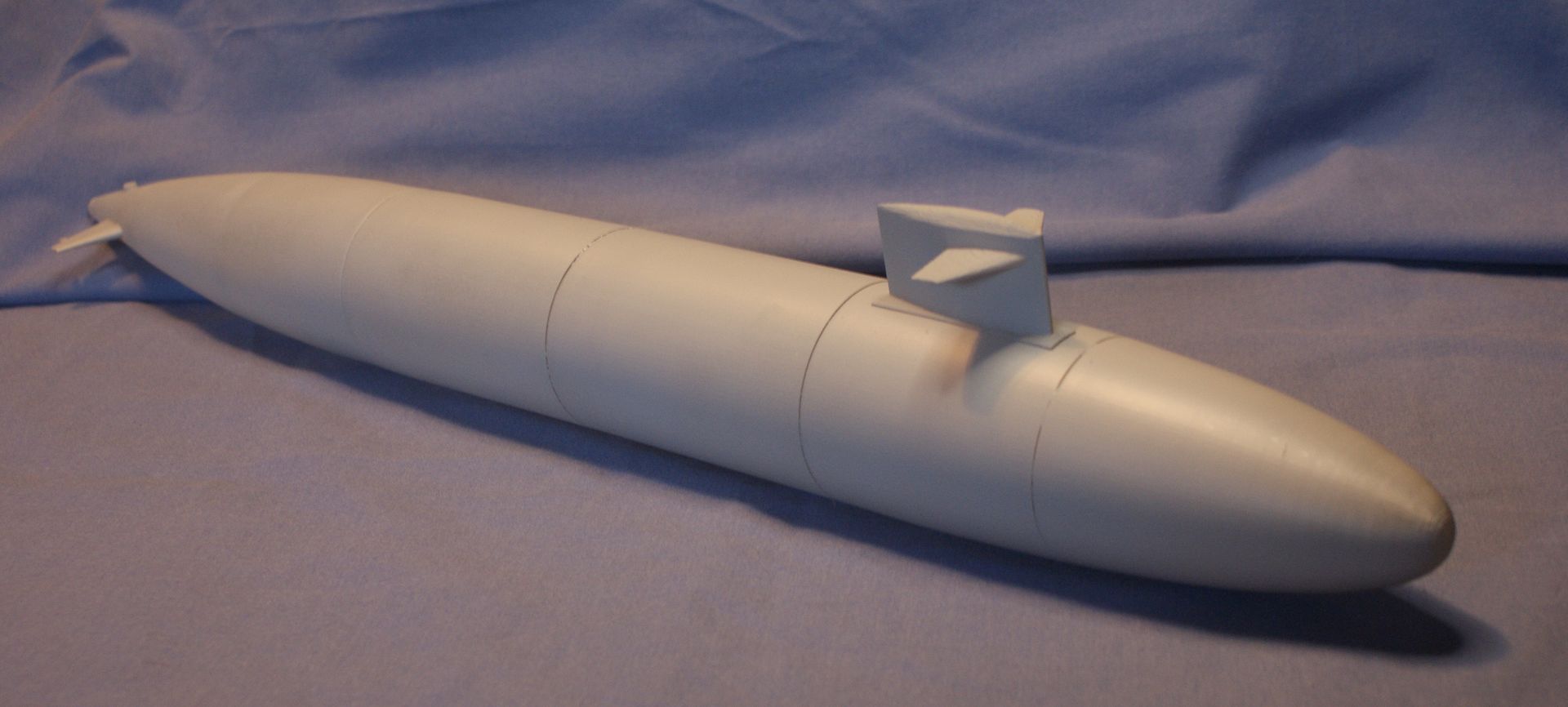
The aft sections are shown next, as are the screw, dunce cap, dive planes and one rudder. The guy that made the parts mistakenly made only one rudder. He realized his mistake and is making (or has already made) another one.
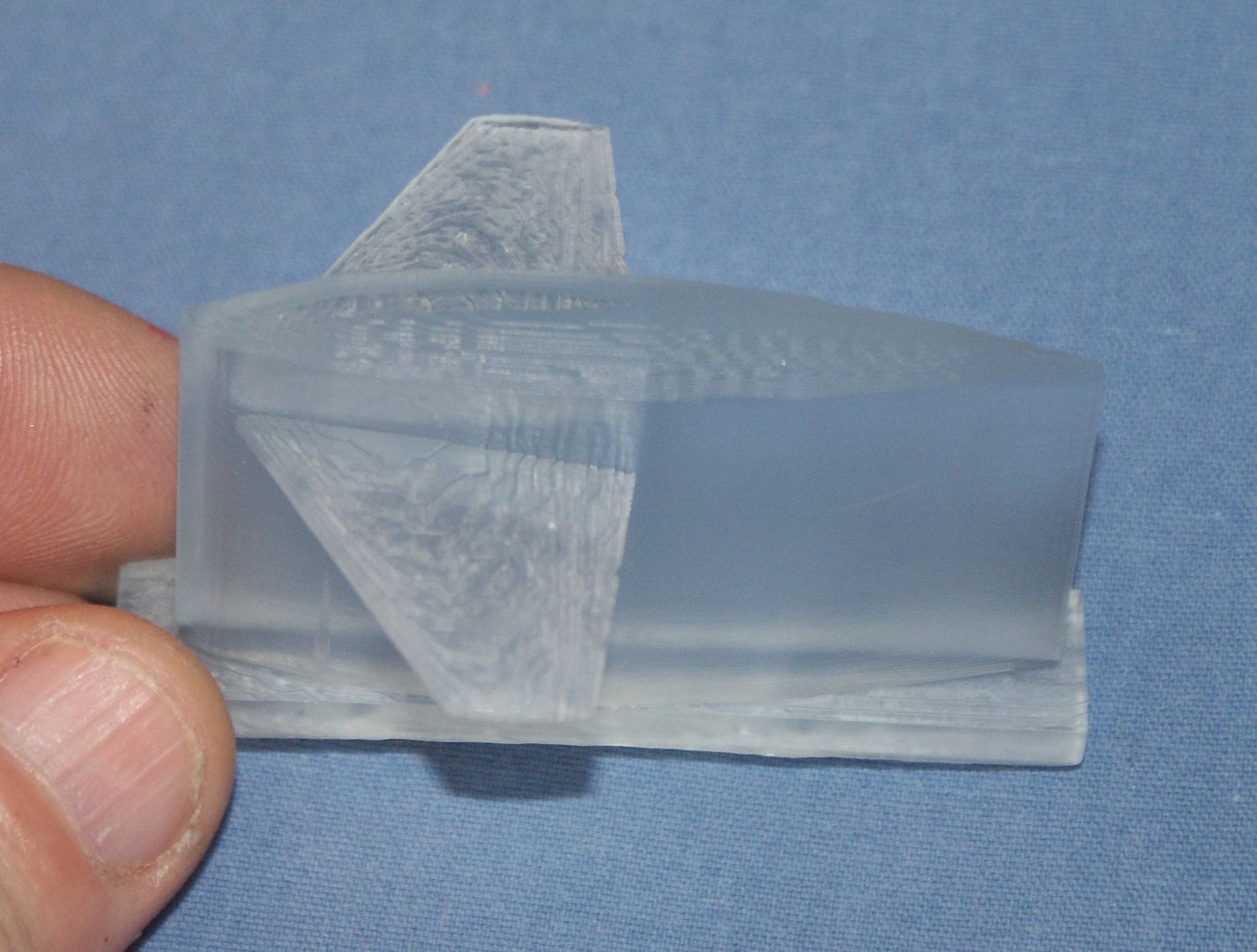
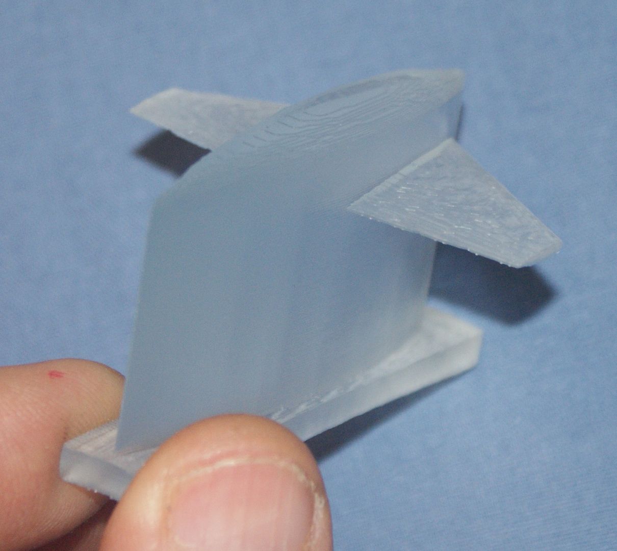
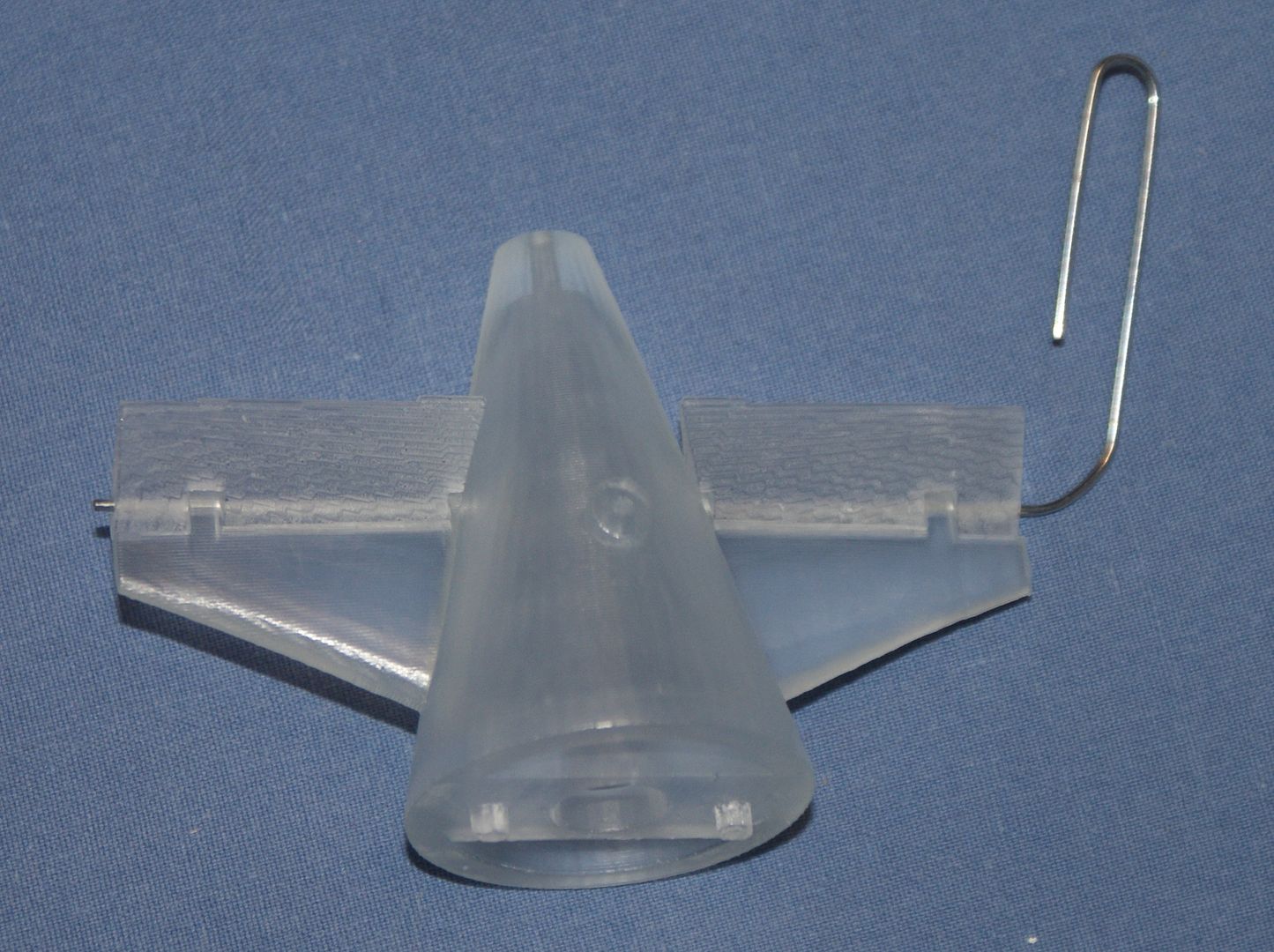
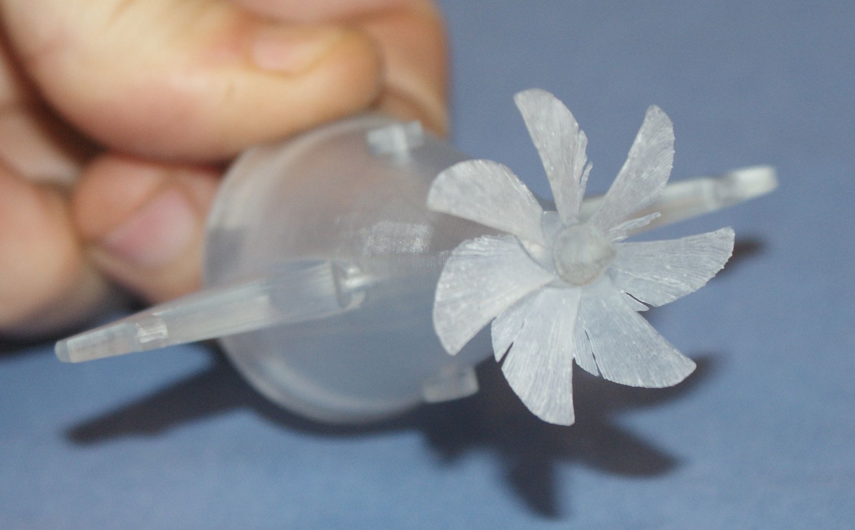
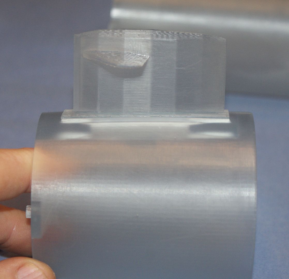
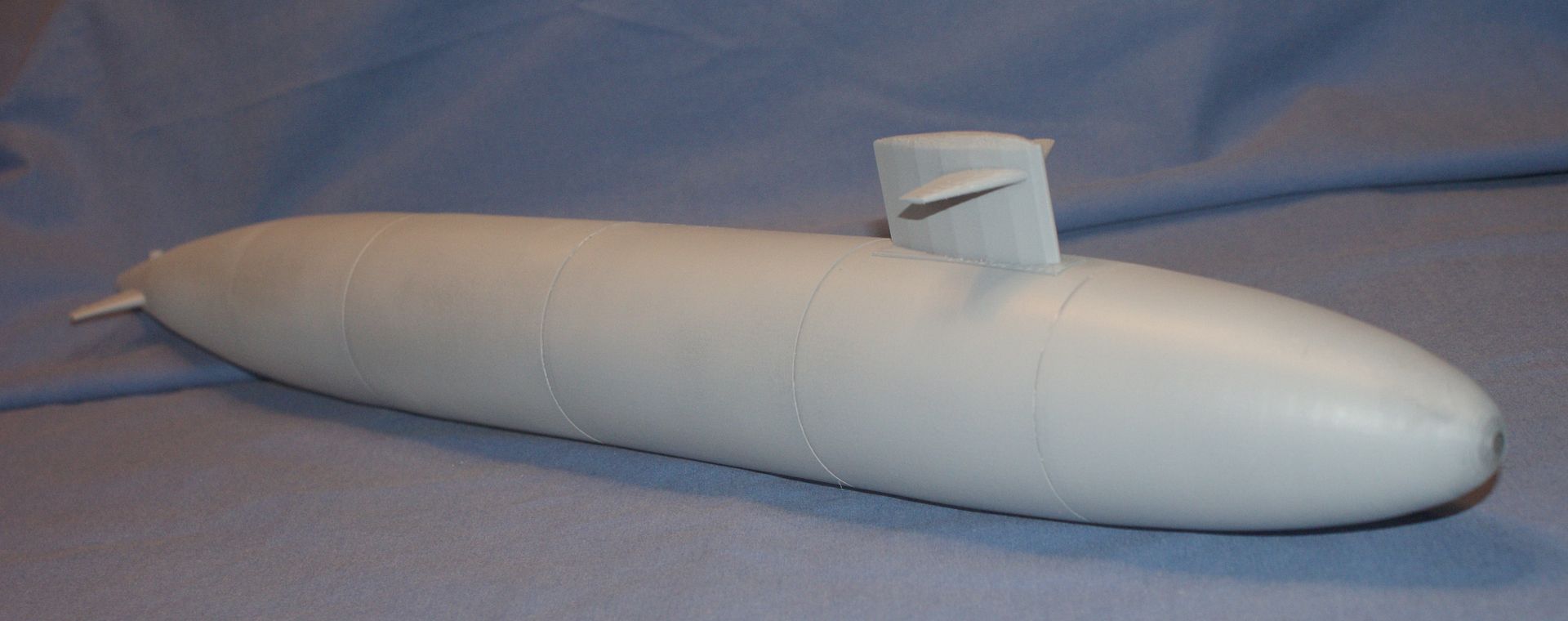
The next three pictures show the sail. Since the parts that were printed were of my initial design, the sail plane is fixed to the sail.

( The most interesting feature of the pictures, to me, is the fact that you can clearly see the layers, even though they are only 0.005” thick. The pattern it makes almost looks like grains on wood. I think this will be easily remedied with a little sanding.
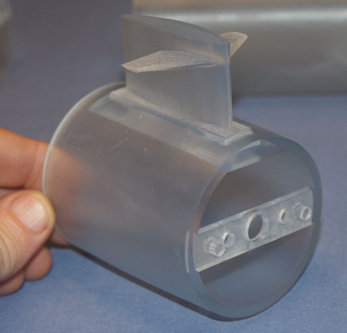
Also note that the sail sides look polygonal and are not smooth. This is because I just used the cross-sections on the plans and did not add extras as I did on the nose. At first I wasn’t crazy about this, but if you look at pictures of the subs, the seams are often clearly visible.
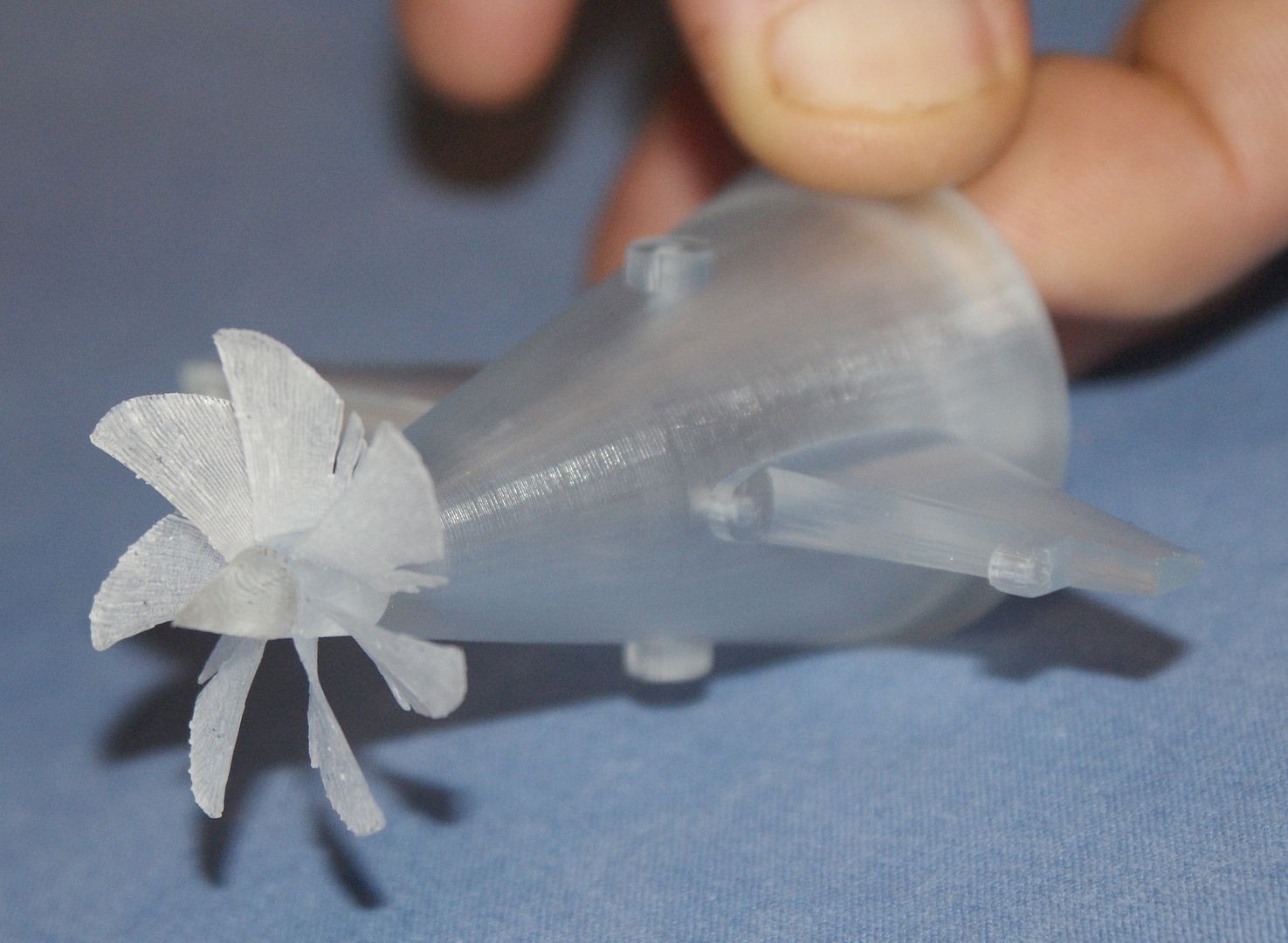
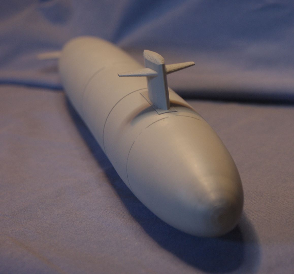
The next image shows close up shots of the one rudder, the dive planes, the screw and dunce cap, and the following image shows an even closer shot of the screw and dunce cap. With these smaller pieces, the resolution limits of the SLA printer used to make the parts starts to become apparent. The aft end of the dive planes is jagged, I think because of the way the parts were made. I am by NO means anywhere near an expert on 3D printing, but judging by the grains, it looks like the parts were made on edge. I think if they would have been made standing up, the jagged edge wouldn’t have happened.
The feathering on the leading edge of the screw blades shows that the part is right at the limit of what the SLA can accurately print. The thickness of the blades is 0.010” and you can see that this this form results in splits occurring along the layer seams. The guy that made the parts thinks that this happened during part processing and is making (or has made) a couple of extra when he prints the rudder he forgot. If I was doing it again, I would make the blade a little bit thicker, say 0.015” – 0.020”, because even though it would be off scale, I don’t think that it would be noticeable and the extra thickness would likely eliminate the feathering. Even so, the screw, even as it is, is useable, with a little work.
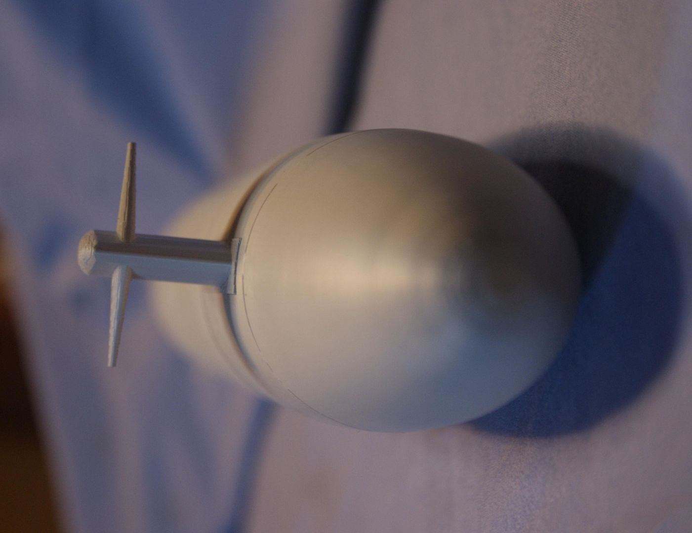
An encouraging feature is the dunce cap. Note how nice and defined the point is and how round and straight the shaft is. The shaft fits neatly into the screw as planned.
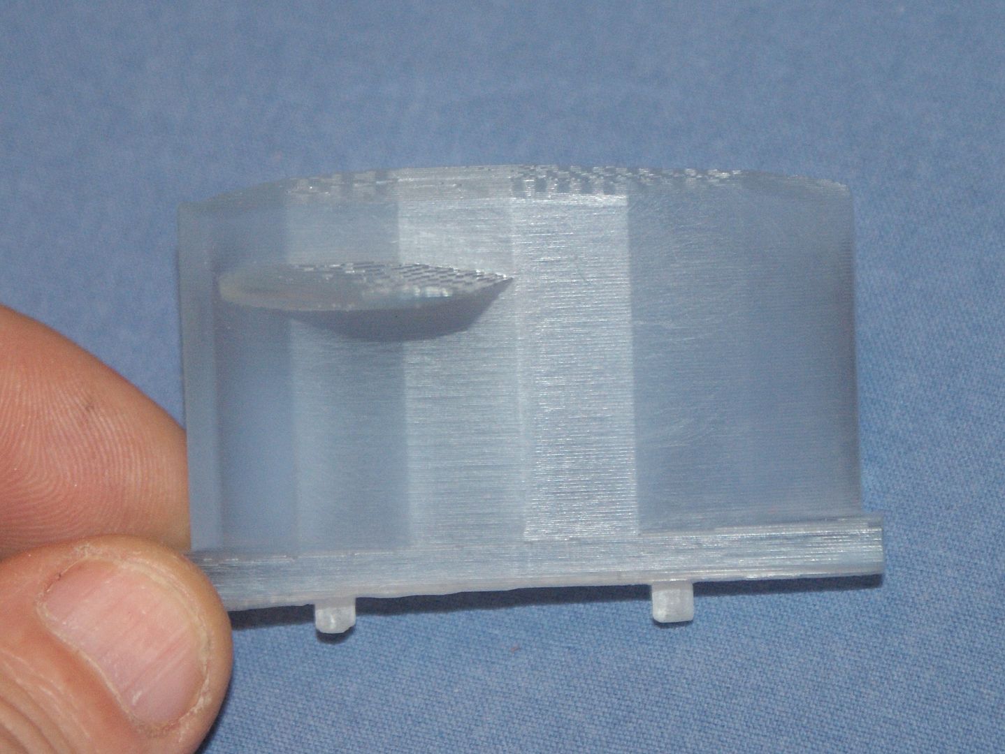
The final picture shows the dive planes temporarily attached to the hull section. The holes are nice and round and properly aligned or the paper clip would not have slid through as it did.
My friend assures me that he will make the detailed parts at some point, or at least make the nose and/or sail to see how it comes out. In the mean time I now get to build the model I have.
Since this is the first submarine I have ever built, I have some questions related to scribing and painting.
First, with regards to scribing… I have only very limited experience scribing and would like some suggestions. What is the best method? Is it better to scribe the plastic itself, or apply a few coats of primer, perhaps over a coat or two of Future, and scribe that?
As for painting… As much as I agree with Sub culture that the model would look pretty cool with LED lights in it, I plan on painting it, hopefully using rattle cans. I have an El Cheapo spray gun, sufficient for spraying Future, but not for painting. Does anybody have any recommendations on what brands and colors I should use to paint it?
I’ll keep you posted as I progress.
CHEERS!!!


 may be a little effort on finishing the propeller ,and it would be perfect
  but you have to be fed up of sand down??