The Ship Model Forum

The Ship Modelers Source
It is currently Tue Apr 16, 2024 10:16 am

All times are UTC - 6 hours [ DST ]


Post new topic Reply to topic  [ 555 posts ]  Go to page Previous  1, 2, 3, 4, 5 ... 28  Next
Author Message
PostPosted: Wed Oct 24, 2012 11:14 pm 
Offline

Joined: Wed Oct 11, 2006 5:46 am
Posts: 412
...nice cabinet! For the Barham I used plexiglass in order to save weight and to be able to move her to any show ... but every time I decided to spare her and she never went out of my home :big_grin:

_________________
http://lsa-space.blogspot.com/


Report this post
Top
 Profile  
Reply with quote  
PostPosted: Thu Oct 25, 2012 1:50 am 
Offline

Joined: Wed Jan 21, 2009 1:51 pm
Posts: 2858
The glass is heavy and the plank is heavy (30mm American Walnut). So, I definitely should be careful when moving the model. Still better than strapping the model in the trunk of my car... :smallsmile:


Report this post
Top
 Profile  
Reply with quote  
PostPosted: Thu Oct 25, 2012 5:59 am 
Offline
User avatar

Joined: Sun Jan 08, 2012 5:36 am
Posts: 422
Location: LA/Cornwall-UK
Very nice work on your scratched HMS Hood.
That is allway's a problem to move finished models to shows and have them sitting on a table with out protection :lol_3: .

You seem to have got that sorted and a very nice job you have done there. :thumbs_up_1:

Watching with Interest on this build. :good_job:

_________________
Cornwall UK


Report this post
Top
 Profile  
Reply with quote  
PostPosted: Sun Dec 23, 2012 9:39 am 
Offline

Joined: Wed Jan 21, 2009 1:51 pm
Posts: 2858
With a few days off, I thought I could finish my tiny pompoms. These are partly soldered, so you'd think the bond is good. However, over the months the bond degraded and parts have fallen off. Worse, superglue will not stick to the surface at all. Hence, this wonderful nice part is now trash. I blame the Tix flux which is supposed to be non-corrosive but in reality is not. Fortunately I already bough a batch of Carr's fluxes, some more toxic than others. So, this means I can implement a small redesign of the etch and see if any parts can be salvaged and spend another 60+ hours on pompoms...


Report this post
Top
 Profile  
Reply with quote  
PostPosted: Sun Dec 23, 2012 10:05 am 
Offline
User avatar

Joined: Thu Aug 27, 2009 11:05 am
Posts: 2261
Location: Paris France
Hello EJFoeth

I hope you find a solution for your "pompoms" !which are in my eyes,the most "real", 350 that I have ever seen :thumbs_up_1:
Cherrs
nicolas

_________________
https://ladiagonaledubosco.blogspot.fr/


Report this post
Top
 Profile  
Reply with quote  
PostPosted: Sun Dec 23, 2012 12:16 pm 
Offline
User avatar

Joined: Sat Oct 06, 2012 4:34 pm
Posts: 967
Location: Cologne / Germany, sometimes Poznan/ Poland and Chessington/ UK
Indeed ... they are the most realistic I ever seen, even in bigger scales where I saw a wonderfull scratch build Pom Pom in 1/72 as single display model at an exposition in France (Chalons sur Marne) ... but this little artwork here is absolutly phantastic! :thumbs_up_1:

_________________
The advantage of wisdom is that you can play dumb; conversely, it is more difficult.


Report this post
Top
 Profile  
Reply with quote  
PostPosted: Mon Dec 24, 2012 10:37 am 
Offline

Joined: Wed Jan 21, 2009 1:51 pm
Posts: 2858
Thanks! Fortunately some parts went quite well... blog updated :wave_1:

Image

My UP launchers were destroyed after receiving a coat of Vallejo primer, a primer that did not stick to the resin or the stainless steel photoetch. I designed new etched parts for the launchers and started all over.

Image

I started by making a small sketch based on John Lambert's drawing and I added a few modifications (The drawing by Lambert is based on photos, so I guess that's fine). I thought it would be easy to repeat these models but these launch tubes were very difficult. The launch tube is a styrene core with a PE part wrapped around it. The styrene core really needs to be accurate with 0.1mm or the PE parts will come off when held in the calipers when drying or in the vise of the drill press. Then the PE part itself needs to be folded accurately. Somehow I thought it would be better if the PE part had 8 folding lines instead of 4, to capture the correct form of the launch tube with the 45-degree edges. Then you need to drill in all the tubes. I reread my previous post where I read I had to make 30 parts before I had 5 good parts. This time I didn't no any better. I fear the Proxxon cross table and the cheap drill press isn't any good resulting in poor reproducibility (a few hundreds of a mm will show up easily in this closely knit pattern). Also, the front of the launcher part has to be completely smooth or the drill will wander. This is why the styrene core is built up from strips but with a single flat strip glued at the end; this really helped with getting a consistent pattern. One major consumer of hobby time when using the drill press is finding a reference point, or zero. I ruin 2 or 3 parts before I find the correct position so I need something better. Trying really hard doesn't cut it! After a while you'll find the entire pattern lined up nicely in the center of the launcher. Two conclusions. One: I need to learn to cast properly to avoid making all these difficult parts over and over. Two: I need a proper drill press with a cross table or CNC milling machine to punch in these difficult patterns.

Image

So here they are, the low yield of several days of trial and error. I did manage to make the gunners viewport open which is an improvement. There are also 12 large ammo lockers and 8 small ammo lockers, one set for each launcher except the one on B-turret. I do not know where they stored the large ammo locker.

Image

And just for fun, all the parts I have made that didn't work out!


Report this post
Top
 Profile  
Reply with quote  
PostPosted: Mon Dec 24, 2012 3:15 pm 
Offline
User avatar

Joined: Mon Jan 10, 2005 6:00 pm
Posts: 12143
Location: Ottawa, Canada
Your blog service doesn't allow hotlinking unless we've already viewed them on the blog and they're in our system's cache :(

_________________
De quoi s'agit-il?


Report this post
Top
 Profile  
Reply with quote  
PostPosted: Mon Dec 24, 2012 3:51 pm 
Offline

Joined: Wed Jan 21, 2009 1:51 pm
Posts: 2858
I (and by that I mean my admin of course) recently installed Cloudflare for some additional features (blocking everything from Russia, for example, eating my bandwidth). Should work now.


Report this post
Top
 Profile  
Reply with quote  
PostPosted: Mon Dec 24, 2012 4:05 pm 
Offline
User avatar

Joined: Mon Jan 10, 2005 6:00 pm
Posts: 12143
Location: Ottawa, Canada
Yep, all checks out!

_________________
De quoi s'agit-il?


Report this post
Top
 Profile  
Reply with quote  
PostPosted: Tue Dec 25, 2012 1:01 am 
Offline
User avatar

Joined: Thu Jan 13, 2005 4:37 pm
Posts: 160
Location: Upcountry Thailand
Hello Evert-Jan,

Like the rest of us, I keep getting amazed by this obsessive quest for the ultimate detail, and by the remarkable level of craftsmanship that you consistently display. Very well done Sir !

One more aspect of your building of HMS Hood makes me happy at a more personal level, in that it must be the only model build around here that is actually taking more time than my build of the destroyer Novik :thumbs_up_1:

Cheers,

Jean-Paul

_________________
Jean-Paul Binot


Report this post
Top
 Profile  
Reply with quote  
PostPosted: Tue Dec 25, 2012 5:08 am 
Offline

Joined: Wed Jan 21, 2009 1:51 pm
Posts: 2858
Let's see that Novik then :thumbs_up_1:


Report this post
Top
 Profile  
Reply with quote  
PostPosted: Sat Dec 29, 2012 2:52 pm 
Offline
User avatar

Joined: Tue Nov 21, 2006 7:44 am
Posts: 542
Location: Germany
Hi EJ,

stunning result with the UP launchers!

About the Vallejo Primer, no problems with resin, white metal and PE so far with it. Do you clean the parts with lighter fluid before adding the primer?

_________________
Cheers,
Christian
_________________
AKA "Painter"
VMF'06 - German Gamblers
Veritable Modelling Friends 2006, Germany


Report this post
Top
 Profile  
Reply with quote  
PostPosted: Sat Dec 29, 2012 3:48 pm 
Offline

Joined: Wed Jan 21, 2009 1:51 pm
Posts: 2858
I did not, I used a soapy detergent. Might be that it contain other substances that left a residue on the parts. However, alcohol on the etched steel parts didn't improve the bond either. I was thinking of trying windex? But lighter fluid... sounds inflammable and toxic? But it it works, why not. Problems that cannot be solved as far as Vallejo is concerned is airbrushing up close. With Wem/Humbrol I can almost touch the parts with the needle and still get a good coat... The parts sprayed with Humbrol were immediately more scratchresistant than the primer (Wem not so). I think I'll stick to Humbrol for a while... much easier than the waterbased paints...

Almost done with the Carley Floats and Denton Rafts... perhaps a day or so more...


Report this post
Top
 Profile  
Reply with quote  
PostPosted: Sat Dec 29, 2012 4:15 pm 
Offline
User avatar

Joined: Thu Aug 27, 2009 11:05 am
Posts: 2261
Location: Paris France
HI EJFoeth

the amount of work on your project Pharaonic,I am amazed by your tenacity,you must have nerves of steel
congrats
Nicolas

_________________
https://ladiagonaledubosco.blogspot.fr/


Report this post
Top
 Profile  
Reply with quote  
PostPosted: Sun Dec 30, 2012 4:28 pm 
Offline

Joined: Wed Jan 21, 2009 1:51 pm
Posts: 2858
Just too much patience :thumbs_up_1: Now that I had a week off, I also had some time to finish some sub projects. New blog post:

I started these Carley floats about a year earlier while we were in the middle of rebuilding our house leaving little space for any modeling (the model was stored). The floats didn't require the model to be at hand for fitting and I wanted to do something. So, some time for minor parts. Ahston et al. (1993) published a thorough investigation on the loss of the HMAS Sydney and a related Carley float; one float was apparently the only remnant for HMAS Sydney, a cruiser lost with all hands after a battle with the German auxiliary cruiser, HSK Kormoran, in November 1941. This report contains a bit of particularly useful information.

Image

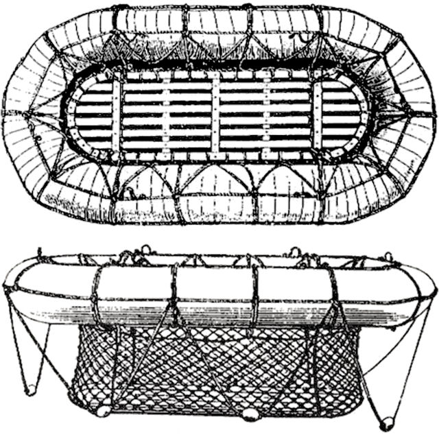
The Carley float is a simple combination of copper tubes with a cork , cotton, and canvas covering. A wooden grating that could be lowered in the water was fastened with rope where you could 'stand'. The even less fortunate were expected to cling on to the ropes around the float making it not much more than a large life ring for groups. I can image you can only survive with such a float for a few days when the weather is favorable. Note the characteristic way in which the rope is wound around the tubing, showing rope going around the entire float and around the circular section, but also rope at an angle at the inside. I wanted to capture this specific detail. Before starting, I had to know which types of float were carried by HMS Hood as the exact dimensions of the floats weren't written down anywhere I looked. Ahston et al. give a table of the types of rafts available at the time:

No Size Tube Diameter
5 3ft 6in x 6 ft 12in
6 3ft 9in x 6ft 6in 13in
7 4ft x 7ft 14in
8 4ft 6in x 7ft 6in 14in
19 5ft x 8ft 14.5in
20 5ft x 10ft 15.5in
14 6ft x 10ft 16in
15 6ft6in x 10ft6in 17in
16 7ft x 12ft 18in
17 8ft x 12ft 19in
18 9ft x 14ft 20in

It is noted that each float was fitted with two paddles (four for No. 18), a boat hook and a painter (?); No 16 to 19 had two ladders. This is information as precise as one could wish.

Image

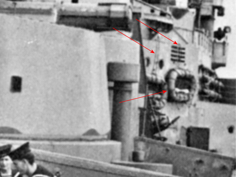
This image shows two Carley floats hanging from a few ropes to the bridge bulkhead and, based on its relation with the bridge structure it's suspended from, I'm quite certain it has to be 5 feet wide based. Note that the ropes differ from the pattern usually observed: there should be some rope at the center of the float but it's not. I haven't seen a single image of a float with the pattern as seen here so I guess the crew repatterned the float? This detail was omitted from the raft models though.

Image

I found out that the closest matches are Nos 19, 20, and 17. The Nos 19 are fitted against the bridge superstructure and on the disinfector house, No 20 is on the superstructure between the funnels and fitted to a side bulkhead of the aft searchlight platform and No 17 is mounted against the aft bulkhead of the searchlight platform. The position and number of floats aboard HMS Hood seems to differ greatly over the years, but I think this is fair assessment of what float goes where for April 1941. Note that the floats to the port side of the forward funnel appear to be lying on some structure. Instead of worrying about the type of Carley float, the real question is: what is this structure? More about this later below.

Image

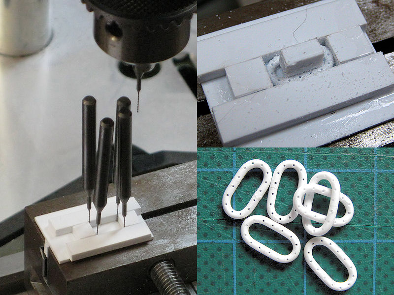
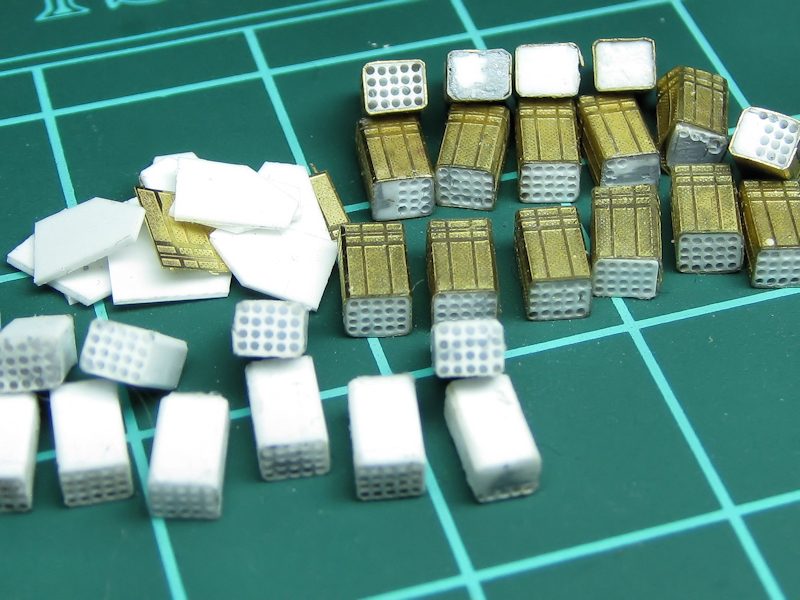
The model floats themselves were made from styrene rod. You first need to bend the rod into shape. I played with boiling them, putting the parts in the oven and I eventually used a cigarette lighter on rod curved around the end of a drill with the right diameter. You only need to heat the part for a fraction of a second or it will melt or start to burn. Each float consists of two halves that do not have a tendency to bend back. Next, I used the drill press to make a drilling jig. At left you can see the outlines with a few 0,3mm drills. I glued thick styrene strip against these drills, let it dry, put in the floats and drilled away. I used the cross table of the drill press for a reproducible pattern. The result is a series of drilled-in rings, here for the 5x10 models.

Image

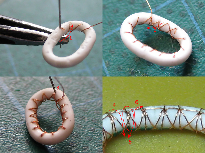
The rope pattern can be simulated with brass wire. Gluing small pieces along the raft gives a lot of glue spots and doesn't really look very good. So, thought it would be nice to sow the ropes with 0.8mm brass wire. The real Carley floats aren't very neat, so making this rope pattern by hand gives with the same variation. Here's an example of the largest float so that you can actually see how these floats were rigged. I started with gluing the end of the wire to the inside to the float, out of sight and not clogging up one of the holes (1). I then went around the float, zigzagging from point to point. The procedure is reversed and the cross pattern in the ropes appears (2). You constantly have to correct the wire with a pair of tweezers or push the wire through the hole with small drill to get the best result (3). Simply pulling the wire taut every few runs doesn't give a good result. Sometimes the wire breaks, but repairs are easy to do.

After the cross pattern was made I continued with the other ropes. I jumped from one hole to the next over the top surface of the float and put the wire through the hole (4). I went round the float once (5) and before pulling it taut, I ran the wire back through the hole, ending where I started (6). The wire around the float lies on top of the wires going from hole to hole, kept neatly in place. In the end, a single wire produces the entire pattern and runs 4 times through each of the 0.3mm holes. About 15cm/6in of brass wire is needed for the smallest float. Glue is added afterwards, at positions that are mostly out of sight. Even though this was fun to do, I wouldn't recommend making all the floats by hand for a project where you need fifty floats. Next time I'll cast a few for easy reproduction.

Image

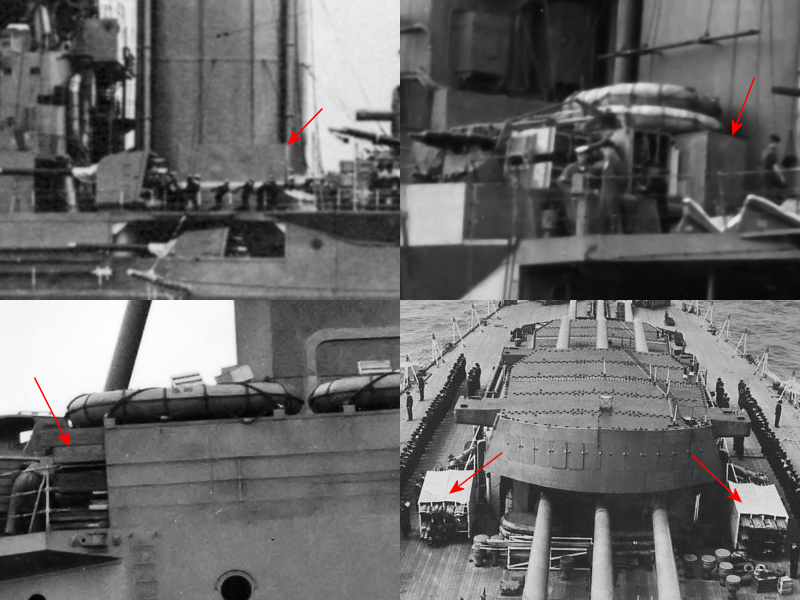
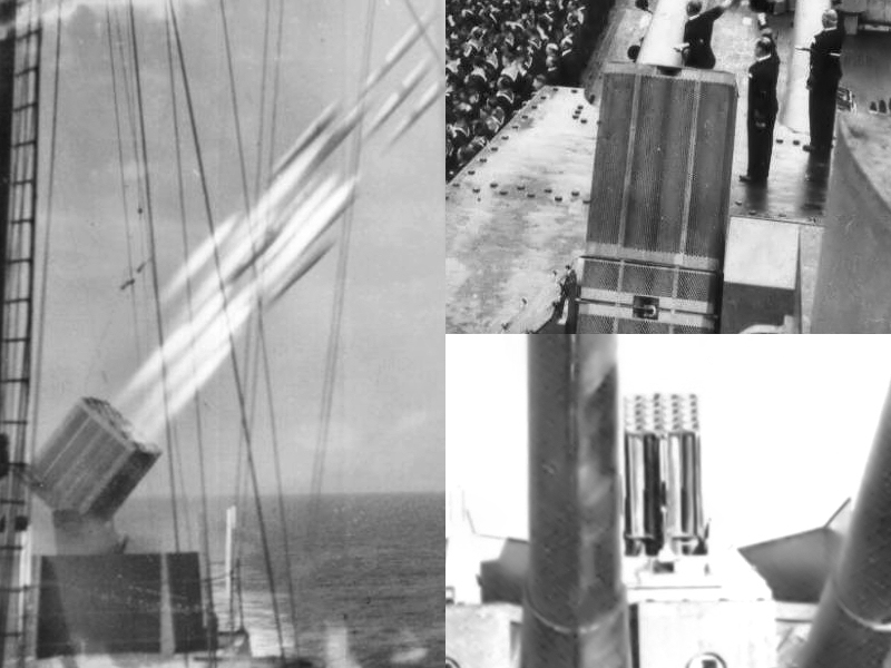
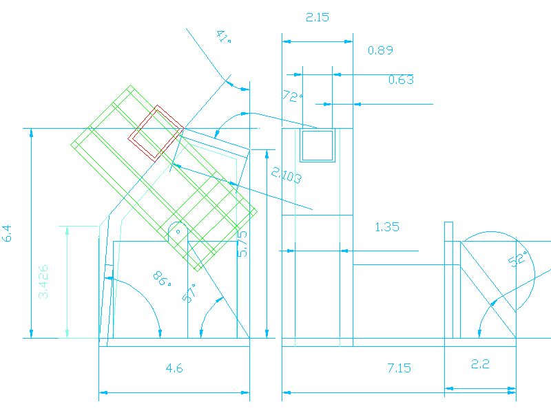
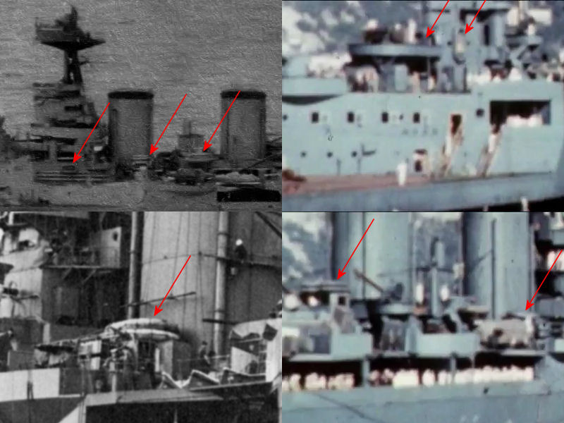
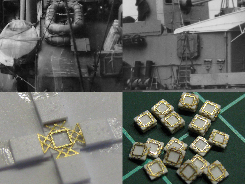
Now for that mystery block near the funnel. In the top left image you can see it hiding in plain sight and you really have to look closely or you won't notice it is there at all. Top right shows the floats stacked on "it'. It appears to be fully closed. So, with no more to go on, what could it be? Other ships have similar blocks. For instance, there are two of them on the boat deck on the King George V class battleships, shown bottom left (plus Carleys on top of it). Notice there's a lot of planks and beams sticking out. Now, HMS Hood also carried a lot of planks and beams next to the funnels, deposited loosely and without any structure, so it might just be a neater and safer way for storage. On either side of the turrets of HMS Rodney (bottom right) you can find similar racks. These are shorted and appear to be oars storage racks? I cannot tell for sure for HMS Hood. I decided to add a randomly detailed rack to HMS Hood, based on the dimensions in the above images.

Image

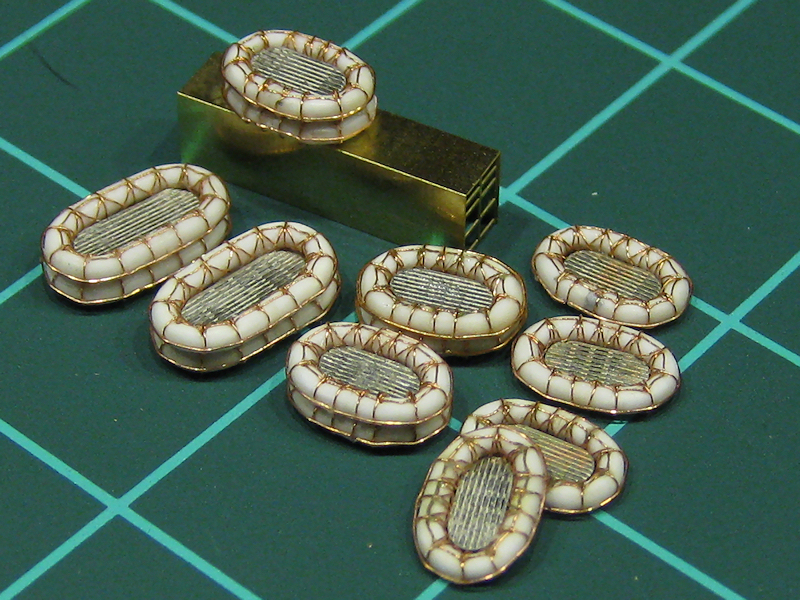
A second wire going around each float was added next. These wires are fixed with glue only and are not as 'sturdy' as the first wire. Some of the 5x8 and 5x10 floats were stacked. For the lower floats, on the wire you can see is actually added, not the complicated pattern.

Image

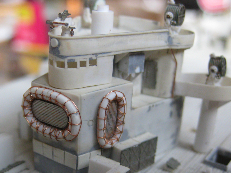
The largest float is glued directly against the aft searchlight platform; there is some room between the etched grating and the outer ring so both are glued separately. One 5x10 float is also added, leaving just enough room for the door below it to open.

Image

One other type of float is present aboard HMS Hood: a series of Denton Rafts. The top left image is of HMS Hood, showing the 16" dinghy, two 5x10 Carley floats and a few Denton Rafts. The image right is the only other image I managed to find. The rafts were made from a simple piece of PE, glued to place usng a small template for easy centering. I have over 20 of these rafts to be added randomly on the structure between the funnels.

1) Ashton, J., Challenor, C., & Courtney, 1993, R.C.H., The scientific investigation of a Carley float at the Australian War Memorial, Technical Papers of the Australian War Memorial, No 1


Report this post
Top
 Profile  
Reply with quote  
PostPosted: Sun Dec 30, 2012 11:22 pm 
Offline
User avatar

Joined: Sun Dec 03, 2006 5:36 pm
Posts: 2160
Location: About 50 miles away from the Gulf of Mexico ( traveling W is you do so :)
Have you started the machinery room :big_grin: i've been following your build-up for sometime, years i think and I got to give it to you she is coming along amazingly!! :thumbs_up_1: :thumbs_up_1: :thumbs_up_1:


Jose :wave_1:


Report this post
Top
 Profile  
Reply with quote  
PostPosted: Mon Dec 31, 2012 12:40 am 
Offline
User avatar

Joined: Sat Jan 08, 2005 7:29 pm
Posts: 1284
Location: Tempe, Arizona
:worship_1: :worship_1: :worship_1: :faint: :faint: :big_eyes: :big_eyes:

_________________
-Abram


Report this post
Top
 Profile  
Reply with quote  
PostPosted: Mon Dec 31, 2012 5:33 am 
Offline

Joined: Wed Jan 21, 2009 1:51 pm
Posts: 2858
I'm not starting anything, I decided to finish things :big_grin: Funnels and derricks are next.... Oh, I damaged something when photographing the model (I hate my model) so back to work... :heh:


Report this post
Top
 Profile  
Reply with quote  
PostPosted: Mon Dec 31, 2012 9:29 am 
Offline
User avatar

Joined: Mon Jan 10, 2005 2:15 pm
Posts: 743
Location: Northants, UK
Can't begin to imagine what the gearbox will look like :big_grin:

Amazing as ever EJ :thumbs_up_1:


Report this post
Top
 Profile  
Reply with quote  
Display posts from previous:  Sort by  
Post new topic Reply to topic  [ 555 posts ]  Go to page Previous  1, 2, 3, 4, 5 ... 28  Next

All times are UTC - 6 hours [ DST ]


Who is online

Users browsing this forum: varifleman and 53 guests


You can post new topics in this forum
You can reply to topics in this forum
You cannot edit your posts in this forum
You cannot delete your posts in this forum
You cannot post attachments in this forum

Jump to:  
Powered by phpBB® Forum Software © phpBB Group