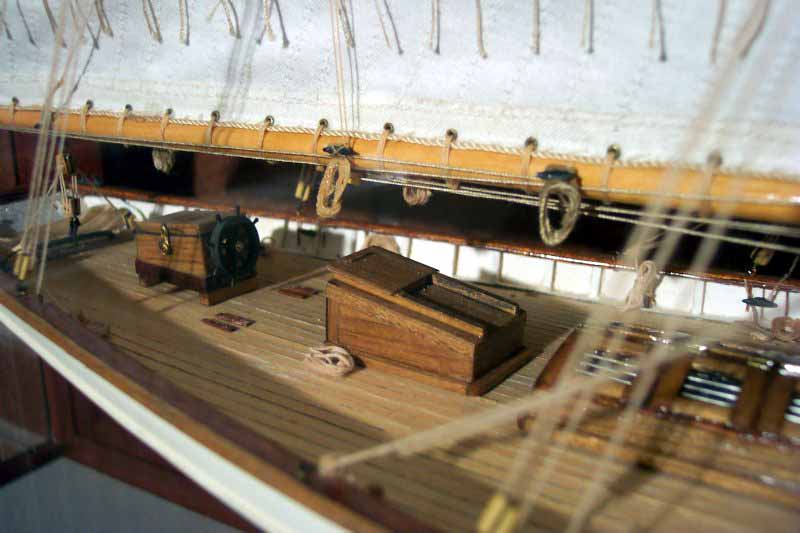
In small steps due to the sweltering heat here in Paris ...
The individual parts were cut such that the front and back pane abutt against the side panes. Since ordinary Plexiglas is much more prone to scratching than silicate-glass, the protective paper is being left on as long as possible. On the inside, however, it would be difficult to remove, once the case has been assembled. This was even more the case with the slightly oldish sheets I am using. Therefore, the paper was completely removed from the side that will face inward. On the outside a narrow strip along the edges was removed to prevent the glue sticking to it. The paper was only removed from the parts that were assembled at that moment.
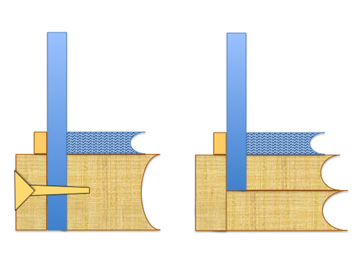
Plexiglas can be cemented together with a variety of glues, including cyanoacrylates or those UV-hardening acrylates that recently entered the DIY market. Epoxy resins, however, should not be used, as their exothermic reaction can stress the Plexiglas, which eventually will lead to fine cracks. If you can produce a perfectly flat edge that is at a right angle to the sheet, you can use a low viscosity cement. In most DIY applications it is better to use a more gap filling higher-viscosity cement.
In order to achieve high quality bonds from both, the optical and mechanical point of view, the best option is to use the Plexiglas-manufacturer’s (Rhöm, now Evonik) own cements. I used Acrifix 192, that is easy to obtain. Acrifix is a light-hardening cement, essentially liquid Plexiglas (more on specialised cements for Plexiglas at
http://www.acrifix.com). This means that the bond has almost the same optical and mechanical properties as the sheet itself. According to the manufacturer, Acrifix 192 has a shelf life of two years. The stuff I bought apparently in 1998 and kept in different fridges at various places around Europe since then worked without any problems. Only the open time was a tad short, but this seems to have been due to my two 100 W worklights. When I used only one and turned it away from the case, I could work longer on the bond.
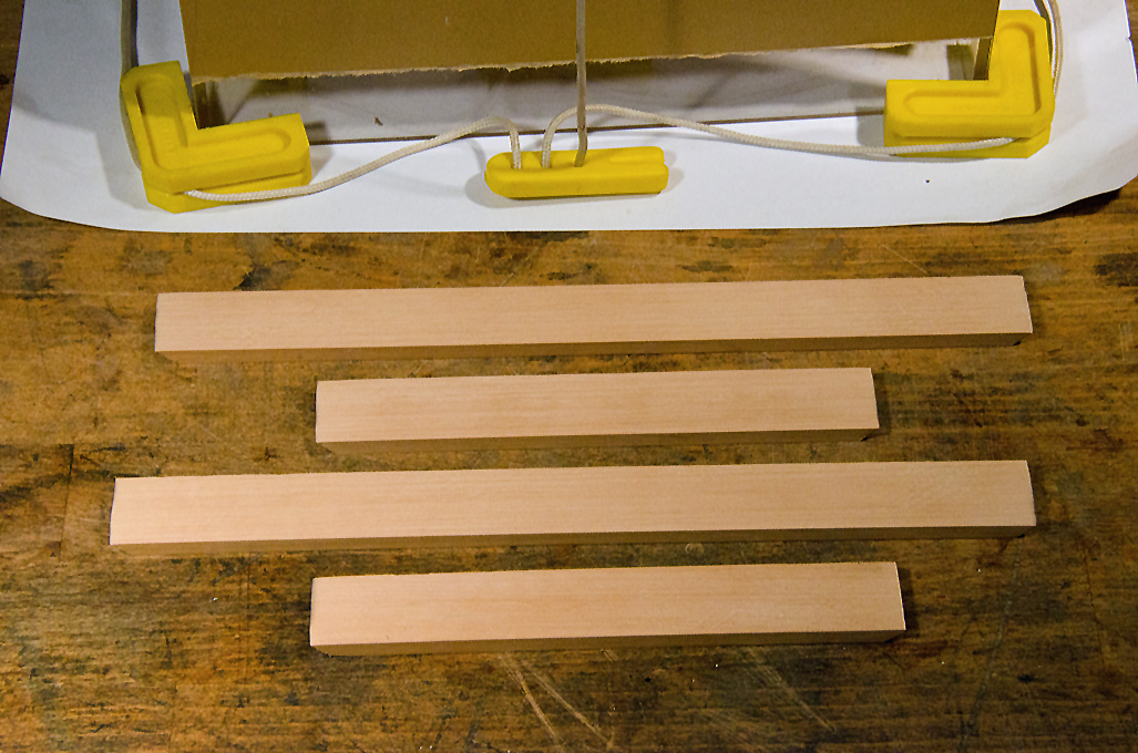
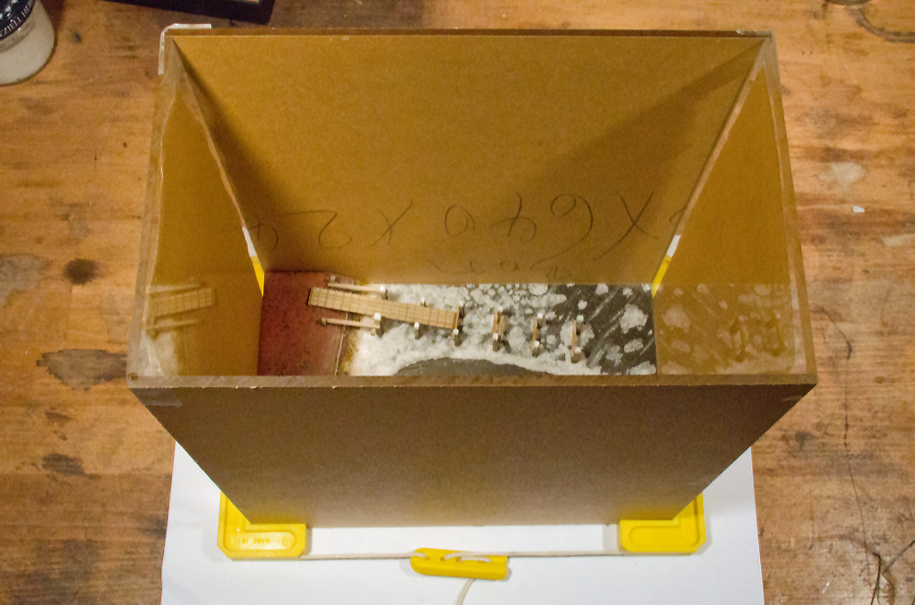 Cementing the parts of the glass case together
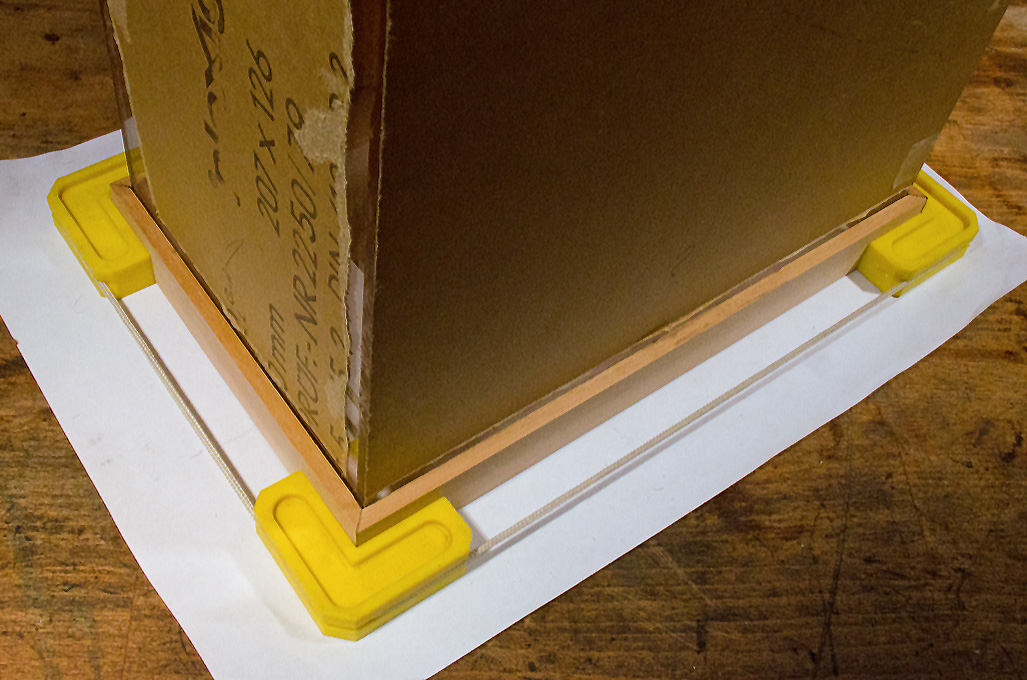
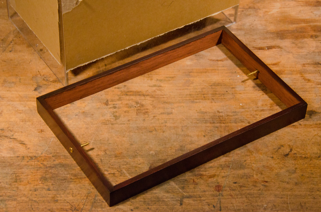
The parts were arranged around the base plate. It would have been better to build the case before starting the scenic display, but my impatience to try out my ‚icing’ skills got the better of me. Now have to work a bit more cautiously when cementing the parts together. The four parts are held together temporarily by a gadget that is normally used to fix picture frames and the likes during glueing. In addition I used cellotape to keep the parts together. In order to allow the application of cement, the fixations are loosened a bit at the respective corner. The cement is applied rather sparingly in order to avoid it squirting out and damaging the surfaces of the Plexiglas sheet. All four corners are cemented together one after the other.
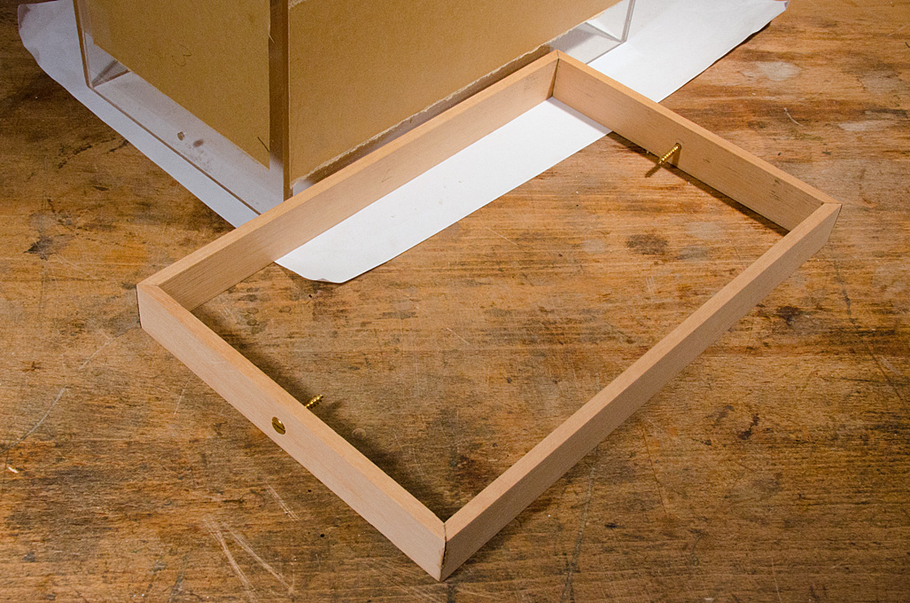
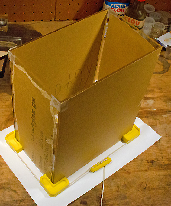 Cementing the parts of the glass case together
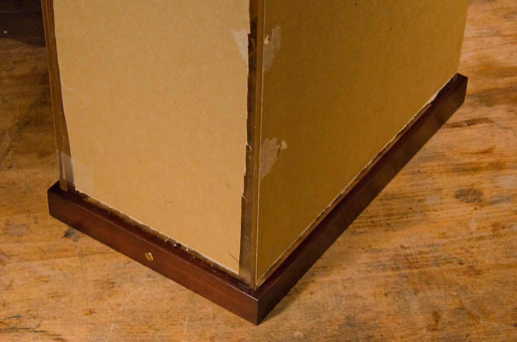
It is possible to obtain a perfect bond without any bubbles – with a bit of practice. However, I wanted to be on the safe side, preventing the cement to squirt out and disfigure the panes, and used a minimum of cement, which may result in some bubbles. This is of no consequence as the corners will be covered later by L-profiles in brass anyway.
To be continued ...
wefalck


 )
)