First time post here so be patient. If I get a little to wordy just tell me to tighten it up. I've been wanting to build a 1/350, CV-6 Enterprise for decades. It's one of those ships thats gone down in history and with good reason - beautiful lines, battle tested and pivotal to winning a war. HMS Victory and USS Constitution are like that in that sense, but as you can still walk through history on their decks, we'll never be able to do the same with Enterprise. Tragic really. Modelling her is the closest thing I can do to walking her decks.
I started a few months ago so I'll post what I've done and work up to the present. I'll also be using the Infini Yorktown PE, which was the only thing available when I got the kit. I see now that Infini released the Enterprise PE...such is the life of a modeler.
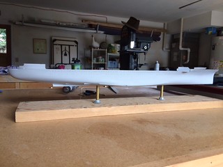
First was the hull. I don't like the faux plating so decided to sand it off. There were some other things I fixed too.
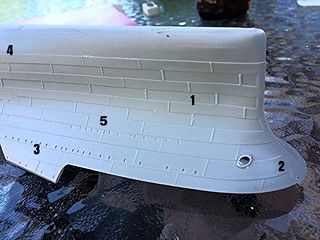
1) filled a small sink mark at the narrowest part of the bow port and starboard, 2) replaced the poorly molded bow leads, 3) made two more leads on the port and starboard that aren't included, 4) made the below waterline armor blister and 5) removed the plating.
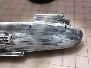
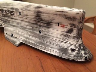
On the stern, 1) there's an open arch that's molded solid. I opened this up and moved it forward a little to avoid the stern/hanger bulkhead that's located right where the arch is molded. 2) is the armor blister, 3) are drilled out portholes that were later puttied over when I noticed from pictures that most were welded over as the war progressed. I'm modelling the Midway fit-out and the only portholes I see are amidship. More and more were welded over as the war progressed until pretty much all of them were gone by the end of the war. 4) is an attempt to scribe horizontal joints at each deck to add visual interest. This was a fail. Then I tried to mask every other scribed area and build up the adjacent area with primer. This also failed. So, I sanded it all off back to flat...hence the crazy quit of colors in my pictures. The smooth hull really looks nice so I decided to keep it smooth and add interest with paint and weathering.