The HullI've used Ross Wattons Anatomy of the Ship Warspite as the base, assuming that the fundamental structure of this ship class were the same. I chose the Academy Warspite kit simply because it has some of the casemate guns in place which I assume provide a starting point. Hah. But I got it half price in a sale so OK. With hindsight, it would probably have been just as easy to scratch build.
The goal is 'credible detailing' rather than complete accuracy as I have nowhere near enough info for that.
In summary, the hull has been modified in 3 ways:
1) Add the casemate structures that Barham had
2) Correct various shapes to match the AOTS profiles
3) Add/replace surface detail such as plating (non-existent on the Academy kit), drains, portholes etc.
About the plating: unlike the Trumpeter kits, there is no plating detail on the Academy hull parts. Luckily, the AOTS book has extensive information on this including a full plate expansion. I've used paper to simulate the plating interpreting the drawing as best I can. Rather than just using a simple over and under set of strips, I have a wide mix of over and under, clinkered with areas of greater complexity of shapes where the curves fore and aft. In some places I've printed out scaled versions of the expanded plate drawings and cut out the more complex parts and used them directly.
About the portholes: All portholes have been drilled out and lined with brass tube to ensure true circles with sharp edges. Eyebrows are from fine copper wire. Some of the porthole heights above various decks seemed a bit odd, in certain place they were much higher than others whereas the AOTS book has the at a common height.
Attachment:
 IMG_2699.JPG [ 162.47 KiB | Viewed 3415 times ]
A) The centerline profile was remodel as per AOTS and the prow brought to a finer edge.
B) Anchor hawse holes have been drilled through and lined. The lining has been shaped to provide a smooth transition out onto the deck with th deck ports given the right shape. The exit holes have been lined with copper wire.
C) I read in the CASF for this ship class that one of the things Academy got right was that the front end of Warspite's bulge differed to the other ships. I've assumed that Barham's bulge was the same as the other ships so it has been filled out to match.
D) Academy provide the paravane foot as a separate foot but is incredibly thick and inelegant. I've made a new one from styrene with paper plating and drilled the holes.
Attachment:
 IMG_2700.JPG [ 172.08 KiB | Viewed 3415 times ]
E) Since Barham still had 6 forward casemate positions, this section had to be cut inward from the kit and given new deck and walls. Additionally the deck forward of the barbettes has a slight incline towards the bow which was added.
F) Warspite retained the center 4 casemates so the forward one had to be made from scratch.
G) As far as I can ascertain, Academy made a big error with the torpedo bulge shape in that these knuckles are supposed to run horizontal for the full length; Academy curves them up fore and aft. Luckily the hull is molded from thick plastic so it is possible to carve out the right shaped from the existing plastic. I did at one point start pricing up Trumpeters Warspite; it was that bad....
H) The grab rails are from this brass wire mounted on copper wire braces so that the rail is about .010" clear of the wall.
Attachment:
 IMG_2701.JPG [ 169.45 KiB | Viewed 3415 times ]
I) The aft casemate position is scratch built.
J) The casemates themselves are completely scratch built as the kit parts seemed undersized and the supporting structure top and bottom didn't feel right. The casemates are made from rolled paper with the viewing ports cut out.
K) The barbettes were salvaged from the kit decks. The decks were discarded as they has a bizarre ridge running down the center; looks like an incorrect interpretation of deck camber.
L) It looks like there is some kind of foot platform around the outside of the casemate so I've added these from thin styrene. Currently they may stick out too far, but that is easy to change.
M) New decks have been added from thicker styrene and given a slight camber to ensure the center of the deck doesn't subside (though not as much as the real ship - that's one for the future). The final deck layer is from .010" styrene cut to include the overhangs around the casemates.
Attachment:
 IMG_2702.JPG [ 179.92 KiB | Viewed 3415 times ]
N) The aft casemates were removed from Warspite so this section is all new scratch building. Gun port plate-over has been added using paper.
O) Aft end of the torpedo bulge knuckles have also been modified to run horizontal.
P) Salvaged kit barbettes. For some reason the Y barbette was significantly shorter than the B barbette but it looks like they should be the same height. So this has been shimmed. Oddly, the missing height corresponded to the thickness of the deck part plastic.
Q) These access hatches were not well represented being simply raised blips which completely lost their shape towards the rear as the side molding limited their definition. SO they've been redone using a custom stencil. I didn't have any dimensional info so I guessed; the hatches scale out to about 3' x 2'.
R) Drains were made from paper formed into 'C' sections and trimmed to shape.
Attachment:
 IMG_2703.JPG [ 166.31 KiB | Viewed 3415 times ]
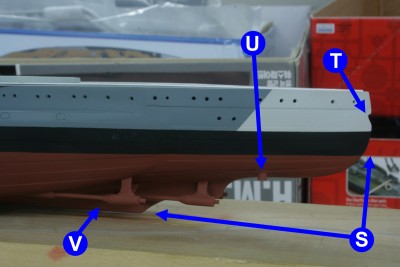
S) Stern centerline profile has been reshaped to match the AOTS drawings. It's lucky that the hull plastic was so thick has significant plastic removal was involved; I had to add styrene sheet on the inside in places as it got too thin.
T) Just like the bow, the stern anchor hawsehole has been drilled, lined and shaped.
U) The kit rudder mounts have been removed and replaced with brass tube and paper stiffeners.
V) The propeller shafts have been given a major rework. The shaft mounts and hull-entry bulges were kept but majorly reworked. AOTS shows that all 4 shafts have the same angle down as they go back but the inner shaft are parallel to the centerline but the outer shafts angle in slightly. With the rework of the torpedo bulge (see later), the kit shafts parts were wildly off.
The A brackets were removed, drilled through to take a brass rod shaft and given fillet stiffeners from styrene. The hull-entry covers were drilled to take the end of the shaft and cut down . From that point it was a matter of tweaking the mounts until the shafts matched card templates with the correct alignment angles. Took quite some time....
Attachment:
 IMG_2708.JPG [ 170.86 KiB | Viewed 3415 times ]
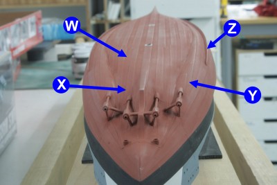
W) To ensure the part of the keel projecting between the propellers had a uniform width (the kit molding had a weird flare in places, as does the 1/700 Trumpeter Barham, which just doesn't seem right., it was necessary to modify the hull shape. using cross sections from the AOTS, this area needed to be filled out, extending the flat bottom area towards the stern.
X) Conversely, this area needed to be scalloped out.
Y) AOTS shows that the rear of the torpedo bulge covers significantly more than the kit with the inside edge running inside of where the outside prop shafts enter the hull. Despite no kit I checked (Trumpeter, Academy or Airfix) having this, I decided to go with the book anyway for giggles.
Z) Bilge keels never seem to be molded right, having a shallow angle (that allows part removal from the mold?) so they've been replaced with a steeper angle and extended forward.
Couple of shots of what's under the covers:
Attachment:
 IMG_2659a.jpg [ 143.78 KiB | Viewed 3415 times ]
Attachment:
 IMG_2660.jpg [ 175.25 KiB | Viewed 3415 times ]
Couple of spurious extras:
Attachment:
 IMG_2705.JPG [ 168.74 KiB | Viewed 3415 times ]
Attachment:
 IMG_2706a.jpg [ 136.52 KiB | Viewed 3415 times ]


