The Ship Model Forum

The Ship Modelers Source
It is currently Fri Apr 19, 2024 2:44 am

All times are UTC - 6 hours [ DST ]


Post new topic Reply to topic  [ 358 posts ]  Go to page Previous  1, 2, 3, 4, 5, 6 ... 18  Next
Author Message
PostPosted: Sun Jan 13, 2019 9:47 am 
Offline
User avatar

Joined: Mon Jan 10, 2005 5:30 pm
Posts: 5386
Location: Nr Southampton England
Marijinn wrote:

>>> thorough and methodical approach <<<
me? nahhh...

you got the wrong guy - thorough and methodical, now that would be Georgy Pek!
now this is methodical and prepared! :thumbs_up_1: :thumbs_up_1:

viewtopic.php?f=59&t=163972&hilit=zs180#p707352


-- whereas I am rather more like making it up as I go along.
The next guy who follows can organise it all in a rational format !! :big_grin:

meanwhile--organised chaos continues in a rather more tangible manner at last

the ' funnel deck '....
there is a lot of work to do in this area; the manufacturers intention was that many dozens of small window frames are intended to be installed into apertures in the casting, however I saw a potential flaw in this plan when I first opened the box 18 months ago;
==> that being of getting everything flush and filled to perfection without messing up the window PE or the black colour behind and the chance of it all going horribly wrong and / or looking messy / bitty

Attachment:
P1230736.jpg
P1230736.jpg [ 807.88 KiB | Viewed 1333 times ]


When the window frames are installed it looked a like this -- the potential issues are self evident.
( note the 3-D printer step lines-- I was Idle... and did not clean them up as I was covering them.... !
ergo no need :cool_2: )

Attachment:
P1230727.jpg
P1230727.jpg [ 704.6 KiB | Viewed 1333 times ]


more skilful (and patient !) people than I may elect to retro-fill and sand it all flush .

Attachment:
P1230728.jpg
P1230728.jpg [ 551.21 KiB | Viewed 1333 times ]


I elected to take a short cut ;

that of having the lifeboat deck faces made as photo-etched overlays

This has been pretty much wholly successful--but not alas without its own minor pitfalls (!)
But I digress--more of that later in this update ( cutting perfect PE ! )

Installing a lot of small window frames/ grilles is very time consuming...

I blacked the window area with a 3B soft lead pencil, and dropped in the window grilles
onto matt Humbrol varnish as the adhesive
( if at later inspection they are detected as crooked or wrong,
they are--unlike with glue-easily flicked off even when set . :big_grin: )


Attachment:
P1230720.jpg
P1230720.jpg [ 781.04 KiB | Viewed 1333 times ]

Attachment:
P1230721.jpg
P1230721.jpg [ 647.01 KiB | Viewed 1333 times ]


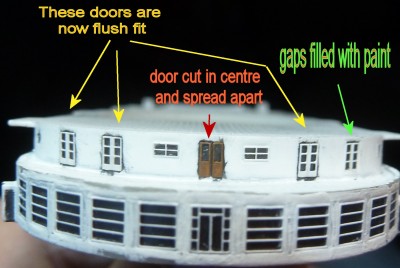
The First class verandah deck has some really nice PE doors in the kit--unfortunately these are slightly too wide for the apertures to sit in dead-flush (as they are on the real ship,) as is middle PE wooden double door, while it is nice,
....is a bit to narrow compared to photos

I would later widen this door; but in the meantime the apertures needed scraping out and making wider
it looks at this stage, neither promising or elegant!

Attachment:
P1230722.jpg
P1230722.jpg [ 618.42 KiB | Viewed 1333 times ]


It improved vastly with some PE ! ( timber door still to be painted and have stretched sprue put in centre split

Attachment:
P1230733.jpg
P1230733.jpg [ 775.22 KiB | Viewed 1333 times ]


The three small square windows either side would not be covered by the PE--
these suffered from being not ever so sharply cast alas

Attachment:
P1230741.jpg
P1230741.jpg [ 566.98 KiB | Viewed 1333 times ]


Attachment:
P1230770.jpg
P1230770.jpg [ 916.64 KiB | Viewed 1333 times ]


The cure here, was to to make my own seperate window frames of the thinnest
appropriate sized PE I could lay my hands on in my ( admittedly huge ) old PE stash

(WEM Koenig 1/350 ladders )

which would match the relief-etched frames of my custom PE

Attachment:
P1230752.jpg
P1230752.jpg [ 677.08 KiB | Viewed 1333 times ]


cutting these accurately was surprisingly tricky - I used the reflection of the PE in the cutting blade to get it mostly right

Attachment:
P1230762.jpg
P1230762.jpg [ 669.23 KiB | Viewed 1333 times ]


The slightly imperfect remainder was held in my flat tweezers ( padded with Tamiya tape )
and sanded with 1500 blunt sandpaper until flat

Attachment:
P1230767.jpg
P1230767.jpg [ 682.84 KiB | Viewed 1333 times ]


Attachment:
P1230731.jpg
P1230731.jpg [ 501.04 KiB | Viewed 1333 times ]


There was a missing window on the casting - above the entrance vestibule

I cut open my PE above the vestibule , inserted a section of window and closed the gap with s/s PE

Attachment:
aft deck windows a.jpg
aft deck windows a.jpg [ 517.42 KiB | Viewed 1333 times ]

Attachment:
P1230787.jpg
P1230787.jpg [ 663.15 KiB | Viewed 1333 times ]


Offering up my spare PE on the originally supplied funnel deck
( not the-replacement funnel deck )

was a wise move as it fitted well

BUT-- as there was a MINOR discrepancy between the the two castings ( o,2- 0.3 or so mm or so overall )
the new deck casting being fractionally smaller ( as evidenced by the packing piece at the bridge end)
Attachment:
P1230631.jpg
P1230631.jpg [ 886.61 KiB | Viewed 1333 times ]


(albeit it would have needed some of this this anyhow!!)


This threw out the window mullion centres ever so slightly but progressively

This required very very small amounts to be cut out of the PE to get the window mullions to align

Attachment:
P1230753.jpg
P1230753.jpg [ 657.47 KiB | Viewed 1333 times ]

Attachment:
P1230756.jpg
P1230756.jpg [ 683.68 KiB | Viewed 1333 times ]


Attachment:
P1230761.jpg
P1230761.jpg [ 822.62 KiB | Viewed 1332 times ]


The cuts were closed off with stretched sprue which after the first coat of paint will be pared
and sanded flush before the next coat.

Attachment:
P1230789.jpg
P1230789.jpg [ 530.84 KiB | Viewed 1333 times ]


The entrance vestibule had window frames cut down to size from spare items of the fwd winter garden
( at the bows)windows.
Attachment:
P1230793.jpg
P1230793.jpg [ 617.16 KiB | Viewed 1333 times ]


This area is poorly photographed; and is not easily visible in aerial photos either as the after-most davit and boat usually obscures the view

Attachment:
20190107_124056.jpg
20190107_124056.jpg [ 198.14 KiB | Viewed 1333 times ]


The casting accurately portrays the hollow in the outside wall ==> kudos!

Attachment:
20190107_124154 - Copy.jpg
20190107_124154 - Copy.jpg [ 231.13 KiB | Viewed 1333 times ]


the solid part of the vestibule I made of vinyl tape

Attachment:
P1230792.jpg
P1230792.jpg [ 671.09 KiB | Viewed 1333 times ]


Attachment:
P1230793.jpg
P1230793.jpg [ 617.16 KiB | Viewed 1333 times ]


Note the hollow to the outside wall has now been added
Attachment:
P1230800.jpg
P1230800.jpg [ 747.77 KiB | Viewed 1332 times ]


well that is it so far -- some more updates as they happen.

More modelling now--less thinking about it !

JB :wave_1:

_________________
....I buy them at three times the speed I build 'em.... will I live long enough to empty my stash...?
http://www.modelshipgallery.com/gallery ... index.html

IPMS UK SIG (special interest group) www.finewaterline.com


Report this post
Top
 Profile  
Reply with quote  
PostPosted: Sun Jan 13, 2019 9:28 pm 
Offline
User avatar

Joined: Fri Jan 11, 2019 4:11 pm
Posts: 62
Just caught with your Build. Will be watching with interest.....Cheers mark

_________________
If I was your Wife I would poison your Tea
If I was your Husband I would drink it

Winston Churchill


Report this post
Top
 Profile  
Reply with quote  
PostPosted: Wed Jan 16, 2019 1:38 pm 
Offline
User avatar

Joined: Mon Jan 10, 2005 5:30 pm
Posts: 5386
Location: Nr Southampton England
In the forward area of the Boat deck there was an ' undercut ' area

In photos of the real ship not much detail can be seen or gleaned as the lifeboats and davits obscure the view ,
and in distance shots these look like simply black voids.

Closer study of images suggested that there may be some windows and certainly doors at each end

Attachment:
8f96fa8b1a983e18df0a4cc2bb7fe333.jpg
8f96fa8b1a983e18df0a4cc2bb7fe333.jpg [ 867.87 KiB | Viewed 1241 times ]


and more continued viewing of the " Normandie-in- colour film (on Youtube)
( its a great and stylish piece of period -film documentary )

I managed to screen grab this image from the film

Attachment:
undercut windows .jpg
undercut windows .jpg [ 611.12 KiB | Viewed 1246 times ]


The centre window would prove to be challenge , by virtue of having the 'twin' vertical bars in the glazing of the centre window...


I elected to use spares of the larger window( same deck further aft) to try and emulate these.

Attachment:
P1230815.jpg
P1230815.jpg [ 983.42 KiB | Viewed 1246 times ]


( a large number wasted --due to the being very fine (and rather a soft ) brass,
a lot of trial and eror, of poor / inaccurate cutting and my own ham-fistedness! )


This involved turning the PE frames through 90 degrees
and cutting them to size to achieve the ' double-bar' window dividers

Attachment:
P1230809.jpg
P1230809.jpg [ 579.4 KiB | Viewed 1246 times ]

( the centre window was made of 5 separate pieces and required 4 seperate frames to get the double bars ,
due to distortion of the brass on the non-use side of the window cut

Attachment:
P1230808.jpg
P1230808.jpg [ 1.02 MiB | Viewed 1246 times ]


and then joining them up- floating on matt varnish on the pencil-blackened surface.

The end result was acceptable and they will be --like the real thing--barely visible probably behind the davits boats!

Attachment:
P1230822.jpg
P1230822.jpg [ 696.38 KiB | Viewed 1246 times ]


I am now concentrating on trying to achieve a more homogeneous 'flatness' of deck-house the walls to vent grilles.
The casting had recesses to house the brass inserted vent grilles--alas these have large ( relatively!!) " valleys " surounding them.

More soon

Jim B :thumbs_up_1:

_________________
....I buy them at three times the speed I build 'em.... will I live long enough to empty my stash...?
http://www.modelshipgallery.com/gallery ... index.html

IPMS UK SIG (special interest group) www.finewaterline.com


Report this post
Top
 Profile  
Reply with quote  
PostPosted: Wed Jan 16, 2019 2:45 pm 
Offline

Joined: Tue Jan 11, 2005 10:56 am
Posts: 8572
Location: New York City
Wonderfully intricate work. It looks great.


Report this post
Top
 Profile  
Reply with quote  
PostPosted: Wed Jan 16, 2019 9:48 pm 
Offline
User avatar

Joined: Sun Dec 03, 2006 5:36 pm
Posts: 2160
Location: About 50 miles away from the Gulf of Mexico ( traveling W is you do so :)
Fantastic job on the windows Jim! :thumbs_up_1: :thumbs_up_1:


Jose :wave_1:


Report this post
Top
 Profile  
Reply with quote  
PostPosted: Thu Jan 17, 2019 3:34 am 
Offline
User avatar

Joined: Fri Jan 11, 2019 4:11 pm
Posts: 62
Ditto. The work you are doing is great.....Cheers mark

_________________
If I was your Wife I would poison your Tea
If I was your Husband I would drink it

Winston Churchill


Report this post
Top
 Profile  
Reply with quote  
PostPosted: Thu Jan 17, 2019 2:51 pm 
Offline

Joined: Tue Sep 17, 2013 12:16 pm
Posts: 350
This is just amazing!

It very interesting to see the parts that already have the PE cladding (?). How smooth and sharp it looks compared to the resin part, even though I believe the resin looks smooth and sharp to the naked eye.

I keep following this thread and learn a thing or two :wave_1:

_________________
CV-8: http://www.shipmodels.info/mws_forum/viewtopic.php?f=59&t=153851
DD-436: http://www.shipmodels.info/mws_forum/viewtopic.php?f=59&t=157123
CVL-24 http://www.shipmodels.info/mws_forum/viewtopic.php?f=59&t=158455


Report this post
Top
 Profile  
Reply with quote  
PostPosted: Mon Jan 21, 2019 3:37 pm 
Offline
User avatar

Joined: Mon Jan 10, 2005 5:30 pm
Posts: 5386
Location: Nr Southampton England
@ hypno 7

Indeed ...PE is so lovely -- flat and homogeneous! - unlike sometimes resin parts...( from all manufacturers! )
=========================================================

the fwd bridge piece was alas not a terribly sharp casting-
Attachment:
bridge casting.jpg
bridge casting.jpg [ 580.37 KiB | Viewed 1127 times ]


-and the bridge windows did just not quite look like photos of the real thing


Attachment:
proud pax on the vorpiek of Normandie.jpg
proud pax on the vorpiek of Normandie.jpg [ 545.9 KiB | Viewed 1127 times ]


As posted earlier ( December 15 ) I had a bridge front overlay and bridge sides made to match the front


Image

The windows on the bridge sides were different from side to side


Attachment:
bridge windows port side.jpg
bridge windows port side.jpg [ 281.86 KiB | Viewed 1127 times ]

Attachment:
bridge -starboard  side windows s 2 ..jpg
bridge -starboard side windows s 2 ..jpg [ 461.69 KiB | Viewed 1127 times ]


To try and keep the proportions correct( ish )
I removed approx 0.4 mm ( by eye measurement !! ) from the fwd face and skimmed a bit off the sides as well,
scraped down the bridge decks ( and broke both sides whilst thinning them down from above and below)
and removed the bridge wing side walls , and filled the remnants of the cast window frames

Attachment:
P1230628.jpg
P1230628.jpg [ 771.93 KiB | Viewed 1127 times ]


This was a challenging bit of bending,
as the PE in stainless is pretty strong ( when compared to equivalent brass)
and required some considerable force with rolling steel rods ( tool handles etc) of different diameters on top of the PE,
on post-it note pads and paperback books..(!)
==> so to keep the planes sweet , smooth and unbuckled
( as opposed to heating the stainless which allows it soften and be more compliant and easier to bend but risk dents and marks)
but the result looks pretty cool

Attachment:
P1050145.jpg
P1050145.jpg [ 870.59 KiB | Viewed 1127 times ]


None of it is finished painting, or indeed glued on yet
but there is endless test-fitting and fiddling.

more soon
JB

_________________
....I buy them at three times the speed I build 'em.... will I live long enough to empty my stash...?
http://www.modelshipgallery.com/gallery ... index.html

IPMS UK SIG (special interest group) www.finewaterline.com


Report this post
Top
 Profile  
Reply with quote  
PostPosted: Mon Jan 21, 2019 3:56 pm 
Offline

Joined: Tue Jan 11, 2005 10:56 am
Posts: 8572
Location: New York City
It does look sharp.


Report this post
Top
 Profile  
Reply with quote  
PostPosted: Tue Jan 22, 2019 1:14 am 
Offline
User avatar

Joined: Fri Jan 11, 2019 4:11 pm
Posts: 62
The new P/E certainly makes a big difference overall and especially to the Bridge Area.....Cheers mark

_________________
If I was your Wife I would poison your Tea
If I was your Husband I would drink it

Winston Churchill


Report this post
Top
 Profile  
Reply with quote  
PostPosted: Tue Jan 29, 2019 8:06 am 
Offline
User avatar

Joined: Mon Jan 10, 2005 5:30 pm
Posts: 5386
Location: Nr Southampton England
progressing well-- habe not been able to find time to post the progress yet.

a small update;

vents grilles


the ship was festooned with ventilation louvres
In 1/700 not really feasible to have scale number of louvres sharply depicted ... so anything we try and do will look over-scale or too busy

--so we have to give the impression of it looking like the real thing might
alas simply popping in the PE grilles into the cats recess was unsatisfactory

Attachment:
P12308151.jpg
P12308151.jpg [ 237.83 KiB | Viewed 1023 times ]


Attachment:
vent.jpg
vent.jpg [ 663.13 KiB | Viewed 1023 times ]


as the real thing was not flush !

in fact they protruded quite a way--some more than others
Attachment:
zz.jpg
zz.jpg [ 492.22 KiB | Viewed 1023 times ]


Attachment:
vent.jpg
vent.jpg [ 663.13 KiB | Viewed 1023 times ]


useful photos of people often reveal interesting detail behind!

Attachment:
gettyimages-515349984-1024x1024.jpg
gettyimages-515349984-1024x1024.jpg [ 382.1 KiB | Viewed 1023 times ]


Attachment:
gettyimages-515170202-1024x1024.jpg
gettyimages-515170202-1024x1024.jpg [ 371.93 KiB | Viewed 1023 times ]


Attachment:
zzz.jpg
zzz.jpg [ 500.08 KiB | Viewed 1023 times ]


The compromise I reached was to add a second set of PE ( available from Blueridge to buy )
and attach them slightly askance to the under layer PE in the recess
this gave a better impression of more louvres

I added some supports to the PE to prevent then collapsing into the recess

Attachment:
P1230785.jpg
P1230785.jpg [ 714.04 KiB | Viewed 1023 times ]


next post will have images show what they look like--
more later today hopefully!

Jim Baumann :wave_1:

_________________
....I buy them at three times the speed I build 'em.... will I live long enough to empty my stash...?
http://www.modelshipgallery.com/gallery ... index.html

IPMS UK SIG (special interest group) www.finewaterline.com


Report this post
Top
 Profile  
Reply with quote  
PostPosted: Wed Jan 30, 2019 4:57 pm 
Offline
User avatar

Joined: Mon Jan 10, 2005 5:30 pm
Posts: 5386
Location: Nr Southampton England
surprisingly hard to make vents look interesting ! :scratch:

herewith a couple of snaps of incomplete superstructure parts in construction.

middle funnel base ( still to receive the waist height handrail as per above photos of the real thing with the ladies and the gentlemen
( and the lights...(?)

Attachment:
P1230845.jpg
P1230845.jpg [ 861.43 KiB | Viewed 958 times ]


one of the (many) superstructure side vents
Attachment:
P1230846.jpg
P1230846.jpg [ 482.21 KiB | Viewed 958 times ]


more of those later
=====================================================

The third funnel base has been a bit of a mission...

the whole casting was( again ) dished in the centre slightly
Attachment:
P1040973.jpg
P1040973.jpg [ 570.81 KiB | Viewed 958 times ]


The vent apertures were partly miscast


These have been sanded off and the structures lowered to compensate their height
when they lids have replaced with some PE parts from my spare stash

Attachment:
P1040970.jpg
P1040970.jpg [ 678.9 KiB | Viewed 958 times ]


there was an odd projection that did not tally with photos of the real thing

Attachment:
P1050148.jpg
P1050148.jpg [ 710.8 KiB | Viewed 958 times ]


Attachment:
zziz..jpg
zziz..jpg [ 459.63 KiB | Viewed 958 times ]


so off it came
Attachment:
P1050150.jpg
P1050150.jpg [ 894.2 KiB | Viewed 958 times ]


The aft face of it is almost entirely made of vent grilles
but the proportions of the structure where -I think--slightly off--being a tiny bit too shallow


This was addressed as below
Attachment:
P1050156.jpg
P1050156.jpg [ 711.24 KiB | Viewed 958 times ]


tediously now of course my previously made wood paper deck was no longer usable as there was a missing bit of " wood. "..
Attachment:
P1050154.jpg
P1050154.jpg [ 810.08 KiB | Viewed 958 times ]


so whilst making a new deck --I took the opportunity of improving the fit
Attachment:
P1050158.jpg
P1050158.jpg [ 785.45 KiB | Viewed 958 times ]


Attachment:
P1050160.jpg
P1050160.jpg [ 569.72 KiB | Viewed 958 times ]


this took a few attempts ( boooringly tedious and repetitive )

Attachment:
P1050162.jpg
P1050162.jpg [ 458.31 KiB | Viewed 958 times ]


with the wood decks tacked in, and the distinctive black perimeter edge added ( visible in above posted image of the real ship)
This was made of thin vinyl tape, split down with a blade and coerced into the curve, and then sealed in place with CA and varnish

The funnel has been test-fitted and it looks ' promising..!
Attachment:
P1230851.jpg
P1230851.jpg [ 762.24 KiB | Viewed 958 times ]


it is now ready for the ' amusing' part-- making the deck vents lids of the PE stock...

more fun soon

JIM B :wave_1:

_________________
....I buy them at three times the speed I build 'em.... will I live long enough to empty my stash...?
http://www.modelshipgallery.com/gallery ... index.html

IPMS UK SIG (special interest group) www.finewaterline.com


Report this post
Top
 Profile  
Reply with quote  
PostPosted: Thu Jan 31, 2019 4:26 am 
Offline
User avatar

Joined: Wed Sep 28, 2011 12:04 pm
Posts: 1818
Location: Paris
Well, my eyes becomes sore, when I recall how small all this is ...

_________________
Eberhard

Former chairman Arbeitskreis historischer Schiffbau e.V. (German Association for Shipbuilding History)

--------------------------------------------------------------------------------------------------------------------------------------------------------------------------------------------

Image Image Image Image


Report this post
Top
 Profile  
Reply with quote  
PostPosted: Thu Jan 31, 2019 10:21 pm 
Offline
User avatar

Joined: Fri Jan 11, 2019 4:11 pm
Posts: 62
I wonder why I am mad enough to work in 700 Scale sometimes but what you are doing boggles my mind..... :woo_hoo: :thumbs_up_1: Cheers Mark

_________________
If I was your Wife I would poison your Tea
If I was your Husband I would drink it

Winston Churchill


Report this post
Top
 Profile  
Reply with quote  
PostPosted: Fri Feb 01, 2019 1:56 pm 
Offline

Joined: Tue Jan 11, 2005 10:56 am
Posts: 8572
Location: New York City
Really great work on the ventilation louvers, and the base for the third funnel.


Report this post
Top
 Profile  
Reply with quote  
PostPosted: Sat Feb 02, 2019 4:17 pm 
Offline
User avatar

Joined: Mon Jan 10, 2005 5:30 pm
Posts: 5386
Location: Nr Southampton England
Thank you gentlemen for your encouraging words!

Whilst I am waiting for the Mk III ( and I hope final! ) version of the stainless steel promenade PE window fret and other additional new parts...

I am still working intensely on all the small structures among other bits.
====================================================

The ship had two large -I guess - air intake(?) vents either side of the sports-deck.

Attachment:
air intakes.jpg
air intakes.jpg [ 331.58 KiB | Viewed 824 times ]

Attachment:
air intakesa.jpg
air intakesa.jpg [ 349.63 KiB | Viewed 824 times ]


These vents had been cast as one onto the sports-deck/funnel deck piece;
and me having made life harder for myself with my paper decks... :scratch:
found it very hard to cut around these in a satisfactory manner .

So I removed them!

using a razor saw and blade to part them from the main deck casting.
They were quite neatly rendered-- and the real think has a beaded lip top edge and a handrail around them

inside view
Attachment:
airintakes 3.jpg
airintakes 3.jpg [ 758.98 KiB | Viewed 824 times ]


outside view
Attachment:
airintakes 4.jpg
airintakes 4.jpg [ 143.61 KiB | Viewed 824 times ]


but the walls were rather over-thick,

Attachment:
P1230640.jpg
P1230640.jpg [ 525.68 KiB | Viewed 824 times ]


removing them allowed me to thin the walls down

Attachment:
P1230645.jpg
P1230645.jpg [ 908.07 KiB | Viewed 824 times ]


add the lip to the apex edges and handrail of wire

as well as fill the 3-d printing steps with paint and sand , resand and sand ....

Attachment:
P1230648.jpg
P1230648.jpg [ 640.67 KiB | Viewed 824 times ]


I am still debating .... if less is more...? should I try and add the internal stiffening stringers --or will that be too busy and overscale.?

===================================================================================

meanwhile the fwd funnel base ....
the cast on vent grilles were poor

Attachment:
P1230517.jpg
P1230517.jpg [ 358.44 KiB | Viewed 824 times ]


having already planned to ' double up' I recessed for the the initial vent PE piece
Attachment:
P1230519.jpg
P1230519.jpg [ 649.51 KiB | Viewed 824 times ]


this is where I should have stopped and checked....

but no--I forged onwards full of gung-ho and installed the PE window frames and doors...
at which point I though the doors were too tall ...

Attachment:
P1050169.jpg
P1050169.jpg [ 617.53 KiB | Viewed 824 times ]


a quick check with a straight edge in all planes proved otherwise

Attachment:
P1050171.jpg
P1050171.jpg [ 678.55 KiB | Viewed 824 times ]


what it did prove....!
was that the casting had a curved lower wall....
and as a result left what looked like a black gap-- but was not.

The correct thing to do would have been to check this first, then add filler and sand to correct profile.

for me however it was too late, as the window frames were irremovable , sandpaper and filler would surely have messed them up.

I needed an escape plan!

after some thought and heart-searching--this is what I did:

the real thing had a handrail at waist height.

I used some decal white stripe to create the correct profile and hid the 'step' with the handrail wire

this was better ,

Attachment:
P1230834.jpg
P1230834.jpg [ 551.16 KiB | Viewed 824 times ]


all I had to now was ...( Ha!)

use a very fine ROTRING pen ( .15) to make the window 'black 'bigger by drawing along the frame edges
( a bit like eyeliner in ladies make-up--only muuuuch smaller ( and much more important ! )

and thereby this would reduce the apparent size of the window horizontal bar.

With the doors seeming too narrow compared to photos of the real ship
I had to make make some door frames

add the lighting rail of thinner wire around the near -top edge
Attachment:
zzz..z.jpg
zzz..z.jpg [ 488.81 KiB | Viewed 824 times ]


and the white protruding 'tops' over the doors....
clean up and improve the paintwork and density of the white,
etc etc

My next posting will show the results of this work. :wave_1:

_________________
....I buy them at three times the speed I build 'em.... will I live long enough to empty my stash...?
http://www.modelshipgallery.com/gallery ... index.html

IPMS UK SIG (special interest group) www.finewaterline.com


Report this post
Top
 Profile  
Reply with quote  
PostPosted: Sun Feb 03, 2019 8:09 am 
Offline
User avatar

Joined: Mon Jan 10, 2005 5:30 pm
Posts: 5386
Location: Nr Southampton England
I have reaced the stage I seem to reach in every model I build these days...

...........the trouble with macro digital photographs and big screens is.....

that NOTHING looks good enough or sharp enough anymore... !
individual small pieces as 'stand-alone' items look ' round' and not 'edgy' enough.

arghhh !

BUT

when viewed at 1/1 scale viewing, and as a part of a whole collective unit I guess it will look OK in the end.
anyhow--

I shall persist!
============================================================================================

the fwd funnel base

adding the door frame of 1/350 handrail

Attachment:
ziz.jpg
ziz.jpg [ 560.3 KiB | Viewed 791 times ]


with the door tops. lighting rail

Attachment:
P1050245.jpg
P1050245.jpg [ 550.54 KiB | Viewed 791 times ]


the middle funnel base with handrail added

Attachment:
P1050222.jpg
P1050222.jpg [ 543.5 KiB | Viewed 791 times ]


and test-fitted to the deck

Attachment:
P1050236.jpg
P1050236.jpg [ 803.35 KiB | Viewed 791 times ]


The trouble with theses handrails-- on the real ship these have approximately 750-100 mm maximum clearance ( 3- 4 inches ) from the 'wall'

I do not think I can manage to do an even gap of around a tenth of a millimetre (0.1 mm) gap ,
anything larger will clunky and overscale

....and most certainly I cannot manage the stand-off supports anywhere near to scale , so I resort to gluing on the handrails and adding small pencil strokes
==> to simulate the SHADOW thrown by the handrail stand-off.

The ' vent farm' of the third funnel base

Attachment:
P1050231.jpg
P1050231.jpg [ 858.35 KiB | Viewed 791 times ]


the top edge of the fwd semicircular wall ( that I had remade in brass ) had a timber capping handrail on the real ship.

I added this in wire-, -so as to hopefully get a better demarcation when painting

Attachment:
P1050233.jpg
P1050233.jpg [ 791.21 KiB | Viewed 791 times ]


apropos demarcation....

the edges of all decks on the ship had a |( liftable in sections ) perforated timber surround to allow water to drain
Attachment:
deck drains.jpg
deck drains.jpg [ 192.26 KiB | Viewed 791 times ]


clearly seen on the rounded sections also ( view from 1 st class on to zig-zag seating deck )

Attachment:
deck frains.jpg
deck frains.jpg [ 708.98 KiB | Viewed 791 times ]


Now... I do know that these were flush with the decking.

BUT... due to my own inability to cut sufficiently accurately a clean butt edge ...

I chose to put the curved sections ON-TOP... ( sacrilege. !! )

BUT...

it gives a sharp demarcation--and when ' disguised' by the handrails immediately adjacent , it should be rather less obvious.

I Felt it was a price worth paying for an overall sharper look.

I gleaned the curved and straight sections from my special ' hand-rail wood capping PE I had made for me.

Attachment:
Normandie_PE_JIM.jpg
Normandie_PE_JIM.jpg [ 332.58 KiB | Viewed 791 times ]


these had a groove relief etched into their underside--my intention being to locate the handrails into them ( utopian maybe ...? :big_grin: )

anyhow--in this instance I used them upside don--the groove adding a bit of relief

and...-if one wants to believe it enough--to give the impression of the timber plank edging as well as the drains--==> need imaginations for that though...!) :cool_2:

Attachment:
P1050242.jpg
P1050242.jpg [ 737.96 KiB | Viewed 791 times ]


onwards...! :wave_1:

JIM B

_________________
....I buy them at three times the speed I build 'em.... will I live long enough to empty my stash...?
http://www.modelshipgallery.com/gallery ... index.html

IPMS UK SIG (special interest group) www.finewaterline.com


Report this post
Top
 Profile  
Reply with quote  
PostPosted: Sun Feb 03, 2019 2:50 pm 
Offline

Joined: Thu Dec 18, 2014 7:58 am
Posts: 155
Location: Oslo, Norway
JIM BAUMANN wrote:
BUT... due to my own inability to cut sufficiently accurately a clean butt edge ...

I chose to put the curved sections ON-TOP... ( sacrilege. !! )


Boo! Hiss!

Who are you, and what have you done to Jim?


Report this post
Top
 Profile  
Reply with quote  
PostPosted: Sun Feb 03, 2019 2:52 pm 
Offline

Joined: Thu Dec 18, 2014 7:58 am
Posts: 155
Location: Oslo, Norway
JIM BAUMANN wrote:
I have reaced the stage I seem to reach in every model I build these days...

...........the trouble with macro digital photographs and big screens is.....

that NOTHING looks good enough or sharp enough anymore... !
individual small pieces as 'stand-alone' items look ' round' and not 'edgy' enough.


The "show at 100% magnification" mode is deadly when using a dozens-of-megapixels camera. User discretion is advised.


Report this post
Top
 Profile  
Reply with quote  
PostPosted: Mon Feb 04, 2019 3:35 am 
Offline

Joined: Wed Jan 21, 2009 1:51 pm
Posts: 2858
Is the wire end on the side of that brass strip? Very subtle. Also, great work and nice to see someone re-engineering an entire model : :thumbs_up_1:


Report this post
Top
 Profile  
Reply with quote  
Display posts from previous:  Sort by  
Post new topic Reply to topic  [ 358 posts ]  Go to page Previous  1, 2, 3, 4, 5, 6 ... 18  Next

All times are UTC - 6 hours [ DST ]


Who is online

Users browsing this forum: SovereignHobbies and 84 guests


You can post new topics in this forum
You can reply to topics in this forum
You cannot edit your posts in this forum
You cannot delete your posts in this forum
You cannot post attachments in this forum

Jump to:  
Powered by phpBB® Forum Software © phpBB Group