The Ship Model Forum

The Ship Modelers Source
It is currently Sun Jul 27, 2025 7:28 am

All times are UTC - 6 hours [ DST ]


Post new topic Reply to topic  [ 35 posts ]  Go to page 1, 2  Next
Author Message
PostPosted: Sat Oct 18, 2014 9:09 am 
Offline

Joined: Tue Jan 25, 2011 9:33 pm
Posts: 59
Fellow Modelers,

U.S.S. Skipjack (SSN-585) was the lead ship in a class of nuclear-powered fast attack submarines
first commissioned in April 1959. These were the fastest submarines in the world, with its new “teardrop” shaped hull design allowing for speeds and maneuverability far beyond anything that existed at the time. A total of six were launched, with only one being lost (Scorpion/SSN-589) in 1968 from unknown causes. The rest of the class served very successfully, and were still considered effective attack submarines when they were individually de-commissioned decades later. Skipjack was the last of the class to be de-commissioned, beginning in April 1990.

In 2012 Moebius Models released a huge 1/72 scale model of this very famous and historic submarine. The kit consists of 60 parts (52 light gray plastic/4 clear plastic/4 photo-etch) and has an overall length of 42”. Master model builder/model maker David Merriman served as the lead-man for Moebius on this project, and I understand he went to a great deal of effort to make sure the manufacturers in China got all of the details and shapes right. Certainly this is (by far) the most accurate styrene plastic model of Skipjack ever made. This is the start of my progress build, so let’s cast off and make some headway…

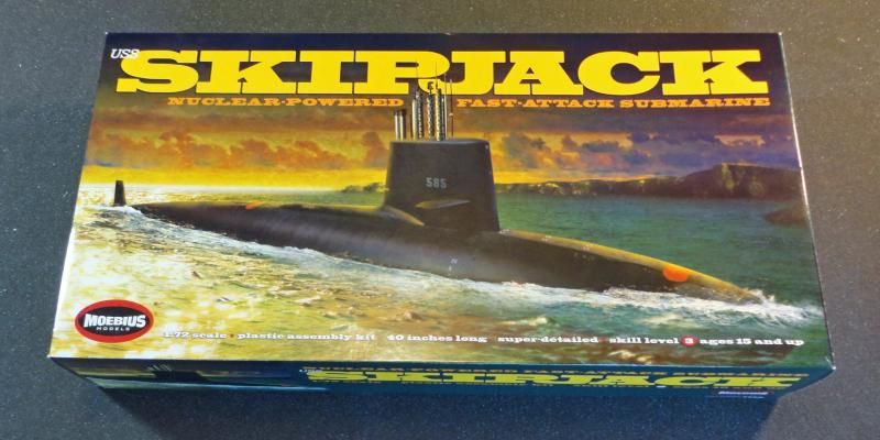
1st Image: This is the model box artwork. I honestly think it would have looked better if it had been a complete body shot underwater, but everyone has an opinion.
Image

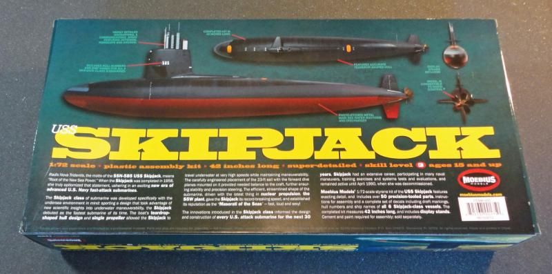
2nd Image: This is the back of the model box. These photos are of the assembled model. I think the same guy that painted the box art built this model, and he did a really nice job. These are helpful as an assembly and painting reference.
Image

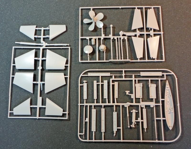
3rd Image: The majority of the kit parts are shown here. The molding is clean and sharp.
Image

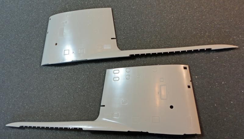
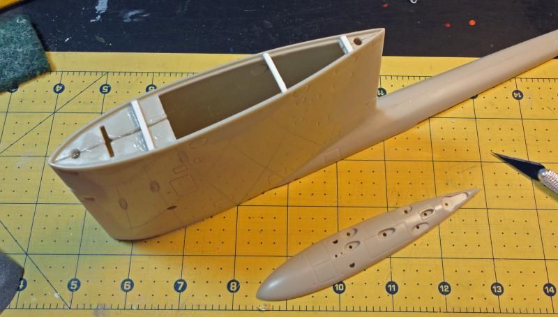
4th Image: The two sail halves are shown side by side.
Image

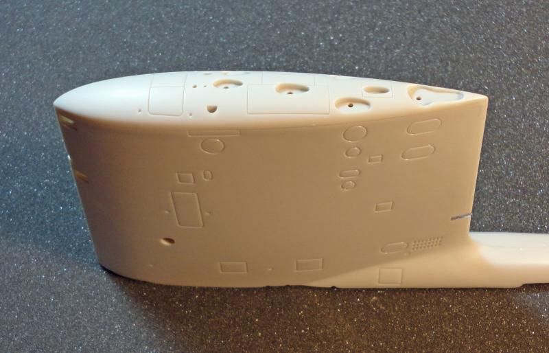
5th Image: The hull comes in four pieces (upper/lower front and upper/lower rear). A little mismatch between the front rear upper pieces can be seen, but this easily removed once the glue is added.
Image

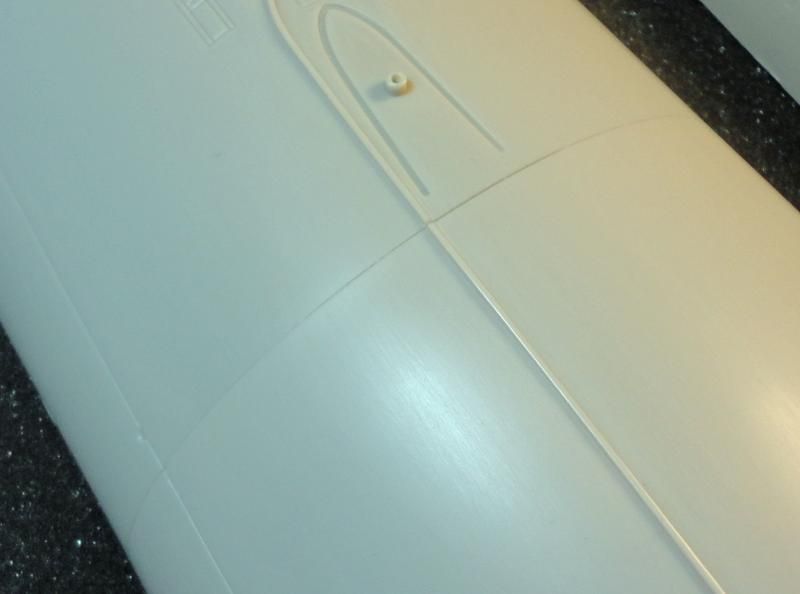
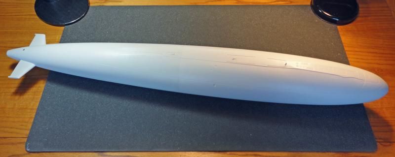
6th Image: The upper hull seam-line is shown after gap-filling superglue was applied and sanded out.
Image

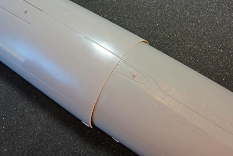
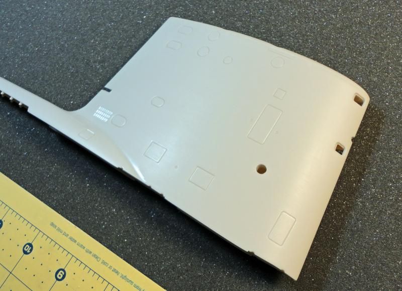
7th Image: The front and rear lower hull pieces have been glued together, but the seam-line has not been filled in or sanded out.
Image

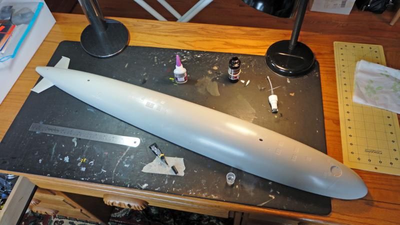
8th Image: Here is an overview of the lower hull assembly on the work table.
Image

9th Image: 5-Minute Epoxy was used to glue the upper and lower hull assemblies. A lot of pieces of masking tape were used to make sure the hull had a tight, gap-free fit.
Image

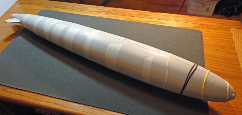
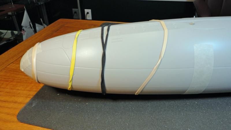
10th Image: The area around the bow was a little warped and required a few rubber bands to make sure the alignment was good while the glue dried.
Image

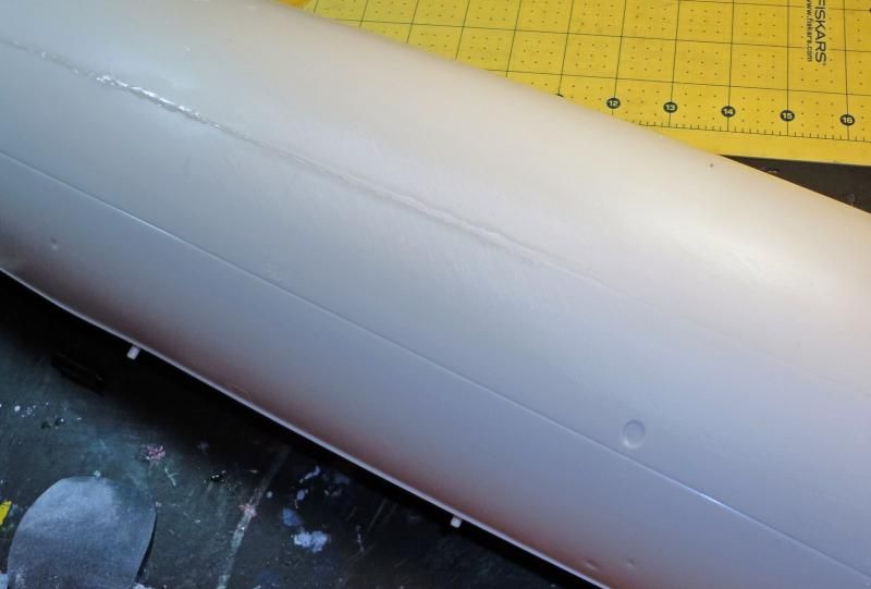
11th Image: This photo shows the hull seam in the process of being sanded out. Over 80 inches had to be removed. The sanding was fairly easy since there were no surrounding raised details in danger of being lost. The only thing to remember was that the seam line is on a radius so you have to be a little careful not to create any flat spots.
Image

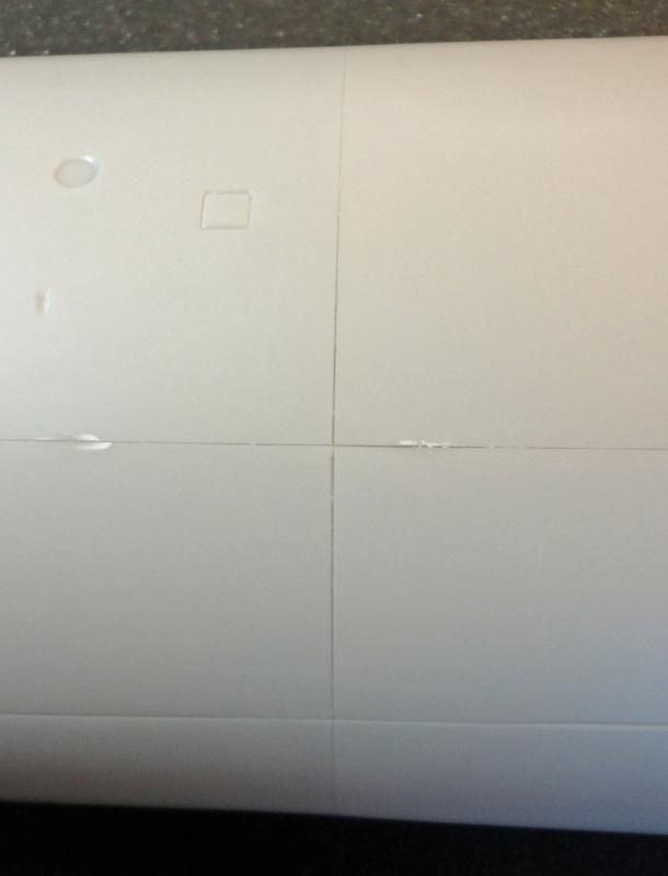
12th Image: All the hull join lines (upper/lower/front/rear) are shown. You can see the gaps are small and the alignment is good, which tells you a good job was done with the engineering and manufacturing of the kit.
Image

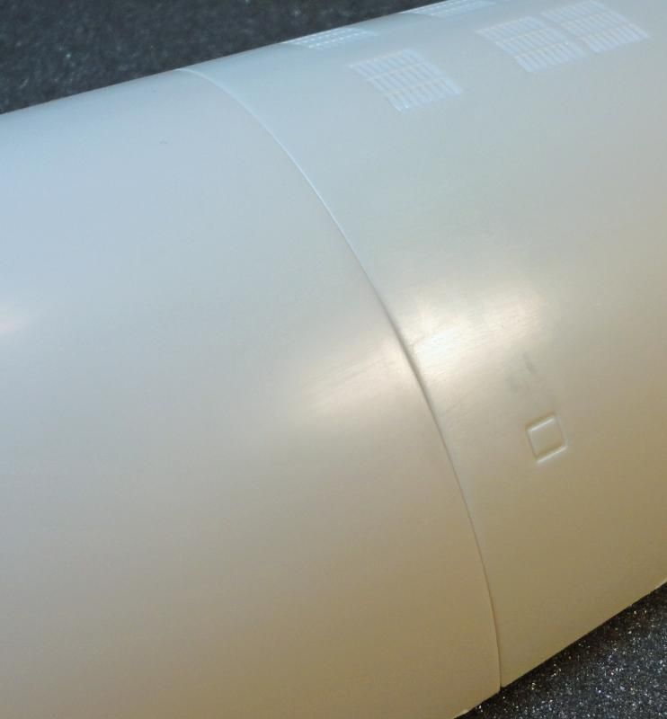
13th Image: Here is the assembly after the mid-hull seam line was sanded out.
Image

14th Image: Works now moves to the sail assembly. The two halves went together very well and it was easy to sand out the seam line. When I added the sail top part it was too wide and overhung both sides by about 1/32”. My fix for this was to cut open the join at the top of the sail and add small styrene pieces to act as spacers. I added three down the length of the sail. Once I had a perfect fit between the sail and sail top, a fair amount of glue was applied to the spacers and original join line.
Image

15th and 16th Image: These two photos show the sail assembly after the top has been added and the seam line removed.
Image
Image

Until next time…

Phillip1


Report this post
Top
 Profile  
Reply with quote  
PostPosted: Sun Oct 19, 2014 11:08 am 
Offline
User avatar

Joined: Sat Feb 26, 2005 7:32 pm
Posts: 960
Location: Seattle, Wa.
At 42 inches long, this kit is to big for me, but I will be following along with your build. Your pictures and build comments will certainly be a great help to others planning on building this kit in the future.

_________________
Gordon


"Then there was one patched-up carrier...."
Vice Admiral Thomas A. Kinkaid


Report this post
Top
 Profile  
Reply with quote  
PostPosted: Sun Oct 19, 2014 12:39 pm 
Offline

Joined: Thu Nov 07, 2013 7:39 pm
Posts: 25
Very cool!
I've heavily debated getting one....

My father's cousin when down in the Scorpion, they grew up next door and were very close.
A month after it disappeared, he received a post card from Spain saying they were to depart the next day and how he just hated being on it and had a bad feeling. He really loved the women in Spain and was considering going awol and back packing through out europe, so if he doesn't make it back, you know why and this post card probably will be the last he ever hears from him....
My father likes to think he did
His father held his memorial five years later.

In 1993, as a young adult, I was up late night channel surfing and came upon a news article on cnn headline news. The government finally released information on the location and photos of the Scorpion. His parents had already passed on at this point not knowing anything.

I look forward to seeing progress with this (even though it's the skipjack) :thumbs_up_1:


Attachments:
100_3193.jpg
100_3193.jpg [ 160.59 KiB | Viewed 4631 times ]
Report this post
Top
 Profile  
Reply with quote  
PostPosted: Mon Oct 20, 2014 6:28 pm 
Offline

Joined: Tue Jan 25, 2011 9:33 pm
Posts: 59
Gordon Bjorkland-Welcome aboard. I hope you enjoy the build.

MadAxeMan-Thanks for sharing that story.

Phillip1


Report this post
Top
 Profile  
Reply with quote  
PostPosted: Sat Oct 25, 2014 9:32 am 
Offline

Joined: Tue Jan 25, 2011 9:33 pm
Posts: 59
Fellow Modelers,

More progress photos…

1st Image: The sail planes (top) and rudders (bottom) are two pieces assemblies. In this photo they are being test fitted to the connecting yoke. The connecting yokes had to be trimmed back a little so the parts had a close fit to the hull.
Image

2nd Image: Here are the ten different assemblies that extend from the sail. They consist of (1) snorkel, (2) periscopes, (1) light, (1) radar and (5) antennas. Four were a single piece and six were two piece assemblies.
Image

3rd Image: Here are all the sail extensions being test fitted to make sure there is no interference before any painting is done.
Image

4th Image: The kit’s whip antennas were too thick and clunky, so they were replaced with small diameter rod. The photo shows the kit parts beside the metal replacements.
Image

5th Image: Cutting several of the masts into three sections served multiple purposes, including making the seam line easier to sand, making painting easier and improving the overall appearance.
Image

6th Image: This photo shows test fitting two of the kit’s four photo-etch parts. They represent the Main Sea Water Suction and Discharge Gratings. These parts did not fit well to the hull and sanding was required to improve the fit.
Image

7th Image: The next step was attaching the sail to the hull. Before this was done two areas (one on the sail and the other on the hull) were masked and painted Testors flat black (1149). These areas are the “open” section of the turtleback behind the sail. Skipjack was nuclear powered, but also had a diesel generator for auxiliary power. The diesel generator exhaust piping was located in this section. You have to paint it now or it is impossible to completely cover after the hull and sail are together.
Image

8th Image: The fit of the sail to the hull was good, but a small bead of 5-Minute Epoxy was applied all around the connection to eliminate any tiny gaps. In this photo you can see the black paint in the turtleback opening.
Image

9th Image: The upper and lower rudders are shown after being glued in place.
Image

10th Image: Here is an overview shot with the hull, sail and rudders finally together. Now that’s what I’m talking about! I will say that before I began building this kit, Skipjack’s shape never made that big an impression on me. However I have now changed my tune. I have to say this is a very sleek, streamlined and attractive design. All of the larger, “teardrop” hull submarines that followed never matched the looks of this class.
Image

Until next time…

Phillip1


Report this post
Top
 Profile  
Reply with quote  
PostPosted: Fri Oct 31, 2014 9:16 pm 
Offline

Joined: Tue Jan 25, 2011 9:33 pm
Posts: 59
More progress photos…

1st Image: The kit comes with two pedestals for mounting. I wanted these to attach to a wood base I purchased at a Michael’s craft store. Unfortunately the largest base I could find was too short to match the mounting holes on the hull. To make the wood base work I located a new mounting hole about 2.5” inward from the stern hole. After the new hole was made the original hole was covered with a very thin piece of styrene.
Image

2nd Image: Changing the pedestal location required modifying the pedestal by adding a styrene ring (or lip) for the hull to sit on. This ring had to sit at the correct height and angle. This was harder to do than I thought it would be and it took me three tries before I got the correct placement. Lastly, a small piece of masking tape was added at the top of the pedestal to create a tighter fit against the hole in the hull.
Image

3rd Image: This photo shows the wood base and kit pedestals being properly located before any painting was done.
Image

4th Image: The wood base was stained and given three costs of satin finish clear polyurethane. The kit pedestals were painted Model Master aluminum (1418) and sealed with Model Master Metalizer Sealer. 5-Minute Epoxy permanently secured the pedestals to the base.
Image

5th and 6th Image: Time to start painting the model! The first area painted was below the mid-hull line, so everything above it was masked off. These photos show how this was done.
Image
Image

7th Image: On the real submarines anti-fouling red paint was used. This is usually a dark, dull red. To get a “hull red” color, I mixed 50% Testors flat red (1150) with 50% Model Master (MM) rust (1785). This photo shows the second of four coats being applied. To prevent any grainy buildup and to keep the finish smooth, I gently buffed the painted surface with a very soft rag between applications.
Image

8th Image: This photo shows the lower hull after all four coats of paint were applied.
Image

9th Image: Let’s talk about recessed panel lines. The Moebius kit comes with very deep recessed panel lines representing the waterline and sonar dome outlines. I have read some criticism about these being included, since they are really not accurate and are heavy-handed. However, by including them the ability to mask and paint these areas is made MUCH easier. My belief is once the model is done the recessed lines will not detract from the finished display, and I am very grateful to Moebius for including them. The area around the lower sonar dome is shown after being painstakingly masked off.
Image

10th Image: My understanding is the sonar domes were made out of glass-reinforced plastic and were painted with hull color paint. The hull paint eventually discolored and wore off, exposing a medium gray primer coating. However, I followed the kit instructions and painted the lower sonar dome a lightened, washed our red by adding white to the base color.
Image

11th Image: The final painting done to the lower hull was airbrushing (at random) a very thin wash of medium gray and dark gray, to break up the single color and give slightly weathered appearance.
Image

12th and 13th Image: These photos show the model after the masking tape was removed.
Image
Image

Until next time…

Phillip1


Report this post
Top
 Profile  
Reply with quote  
PostPosted: Sat Nov 01, 2014 6:38 am 
Offline
User avatar

Joined: Sun Mar 13, 2005 11:51 am
Posts: 2432
Location: Belgium
Following for a while. You're making great progress and the kit itself looks quite sharp!
Love that hull shape, like a bullet :heh: :thumbs_up_1: :thumbs_up_1:

_________________
The merchant shipyard


Report this post
Top
 Profile  
Reply with quote  
PostPosted: Sat Nov 08, 2014 4:00 pm 
Offline

Joined: Tue Jan 25, 2011 9:33 pm
Posts: 59
Neptune-Thanks for the compliment

The painting progress continues…

1st and 2nd Image: After the red paint fully cured everything below the mid-hull was masked off.
Image
Image

3rd Image: This photo shows the first coat of Testors flat black (1149) being applied. Like the lower hull, a total of four coats were added with each coat being buffed with a very soft rag to produce a smooth finish. On the real submarine an anti-fouling black is used on everything above the waterline. On FBM (fleet ballistic missile) submarines a very dark purple paint is used between the mid-hull and waterline, but this turns black after exposure to seawater.
Image

4th Image: Here is the model after all the black paint has been applied. It was a tedious chore using a regular size airbrush on such a large subject, but I never use paint spray cans so I had to be patient and gut it out. I will say the submarine looks a lot meaner and tougher now that it is painted.
Image

5th Image: The upper sonar dome is shown masked off and ready for painting. I used MM dark ghost gray (1741) to represent the gray primer.
Image

6th Image: After the upper sonar dome was painted I was not happy with the demarcation line between the black and gray. It was not as sharp as I wanted it to be. To correct this I carefully masked over the gray sonar dome, hoping I would have better control over-spraying with black.
Image

7th and 8th Image: These photos show the upper sonar dome after my second painting attempt. The demarcation lines turned out very sharp and I am happy with the way it looks.
Image
Image

10th through 12th Image: The next area to be painted was above the mid-hull line and below the waterline. Masking began with 3/16” wide masking tape strips carefully placed along the recessed panel line. Small, curved pieces of tape were used around the waterline location. After the waterline was masked, larger pieces of tape were used to cover everything above the waterline.
Image
Image
Image

13th Image: The assembly is shown here completely masked and ready for painting.
Image

14th through 18th Image: I wanted my model’s hull weathering to look similar to what I had seen on David Merriman’s 1/96 scale Skipjack RC model. Two photos of it are shown. Also shown are several photos of nuclear submarines in dry-dock, showing (to varying degrees) how the black paint between the mid-hull and waterline oxidizes to a chalky, light green color.
Image
Image
Image
Image
Image

19th Image: For my “oxide green” I mixed 50% MM SAC Bomber green with 50% Testors flat white. A concentrated, 3/16” wide band of this color was airbrushed around the top of the waterline.
Image

21st Image: For the next weathering step, the same color was applied further down the hull. The application was less concentrated and more random.
Image

22th Image: For the final weathering step, a lightly concentrated overspray of MM flat gull gray was applied over most of the area including the stern section. Note that both the oxide green and flat gull gray paints were thinned down to washes before they were used.
Image

23rd through 25th Image: The assembly is shown after the masking tape is removed above the waterline.
Image
Image
Image

26th through 30th Image: The assembly is shown after the masking tape is removed below the mid-hull section.
Image
Image
Image
Image
Image

Until next time…

Phillip1


Report this post
Top
 Profile  
Reply with quote  
PostPosted: Sat Nov 08, 2014 4:10 pm 
Offline
User avatar

Joined: Mon Nov 11, 2013 11:01 pm
Posts: 1257
Location: Detroit area
Awesome progress, the paint job is looking really fantastic!

_________________
Sean Nash, ACG (aircraft camo gestapo)

On the ways:
1/200 Trumpeter HMS Nelson
1/700 Tamiya USS Yorktown CV-5

In the stash:
1/35 Italiari PT-109
1/35 Tamiya "Pibber" Patrol Boat
1/350 Trumpeter USS Yorktown CV-10


Report this post
Top
 Profile  
Reply with quote  
PostPosted: Sun Nov 09, 2014 8:09 am 
Offline
User avatar

Joined: Sun May 20, 2012 6:01 am
Posts: 409
Location: Ontario Canada
That's a great looking build,Phillip.Earlier this week,I was checking out the
Seaview kit on the Moebius website.I missed that Skipjack kit.

Scott

P.S. It's about a Sturgeon,not a Skipjack,but just finished reading a great
book."Stalking The Red Bear",by Peter Sasgen."The True Story of a
U.S. Cold War Submarine's Covert Operations Against The Soviet
Union".

_________________
K494 HMCS Arnprior
Royal Canadian Navy


Last edited by K494 on Sun Nov 09, 2014 9:18 am, edited 1 time in total.

Report this post
Top
 Profile  
Reply with quote  
PostPosted: Sun Nov 09, 2014 8:51 am 
Offline

Joined: Tue Jan 25, 2011 9:33 pm
Posts: 59
Goodwood-Thanks for the compliment.
K494-Thanks. This same model is now available through RevellAG. I think it has a different decal set.


Report this post
Top
 Profile  
Reply with quote  
PostPosted: Sun Nov 09, 2014 9:17 am 
Offline
User avatar

Joined: Sun May 20, 2012 6:01 am
Posts: 409
Location: Ontario Canada
Phillip1 wrote:
Goodwood-Thanks for the compliment.
K494-Thanks. This same model is now available through RevellAG. I think it has a different decal set.

Thanks for the info about the RevellAG kit,Phillip.

_________________
K494 HMCS Arnprior
Royal Canadian Navy


Report this post
Top
 Profile  
Reply with quote  
PostPosted: Sat Nov 15, 2014 3:54 pm 
Offline

Joined: Tue Jan 25, 2011 9:33 pm
Posts: 59
Fellow Modelers,

More progress photos…

1st Image: To improve the appearance of the lower hull grates/vents I masked off the outline, burnished dark gray pastel dust into the recesses and dry-brushed the lower hull color over the raised areas.
Image

2nd through 5th Image: The next item on the list was painting the two emergency buoys. The first photo shows the outlines being carefully masked off. The second photo shows the tape applied to prevent overspray. The third photo shows the buoy after painting. I wanted the buoy color to appear washed out and faded so I used Floquil reefer orange (F110030). The final photo shows the aft emergency buoy after removing all the masking tape.
Image
Image
Image
Image

6th Image: The decals were added next. The only markings applied were the hull number to the sail (585) and the name (Skipjack) at the end of the turtleback. I used Aeromaster and Superscale decals for this. Almost all of the clear decal film was cut away, and each number/letter was applied as a separate decal. Doing this, and using multiple applications of Micro-Sol and Walthers Solvaset (the strong stuff), allowed me to get a “painted on” look with the markings without having to add any gloss coating. The photo shows a piece of masking tape was used to help line up the decals before any setting solution was added. I did not include the draft numbers on the hull or upper rudder. There is some irony with my choice of markings, since the submarine name and hull number are present for a very short time (i.e. commissioning and publicity photos), then they are removed. The draft numbers remain for the life of the submarine.
Image

7th and 8th Image: Here are two views of the assembly after all the decaling was finished.
Image
Image

9th Image: I included this photo with my hand as a reminder how large this model is.
Image

10th Image: Only a small amount of water streak staining was added above the waterline. Some of it can be seen in this photo. I applied dark gray pastel dust then spread it out with “down strokes” from a soft wide brush.
Image

11th through 14th Image: In these photos the model has been permanently attached to the base with 5-Minute Epoxy. I am always relieved when I can get to this point on a ship or submarine model, since it means I no longer have to handle the hull and risk damaging the paint finish.
Image
Image
Image
Image

15th through 18th Image: Next on the list was painting the sail masts. Four of the masts have a light gray/dark gray mottle camouflage pattern. This camouflage makes it much more difficult to detect vertical objects at great distances. First the entire mast was painted Floquil neutral gray (303176). Next the “mottle” shapes were drawn with a pencil onto a piece of masking tape. These shapes were cut out with an x-acto knife and added to the mast. My only rule on applying the mottling was trying to keep equal spacing. The mast was then painted MM dark ghost gray (1741). The last photo shows the finished mast after the masks were removed. The mottle masks were tedious to cut so I used the same ones for all four masts.
Image
Image
Image
Image

19th Image: The only “horrible” part of the entire model is the dish for the SS-2 Radar (Part 48). Instead of being a fine mesh screen it is a thick blob of plastic. I replaced it with a photo-etch antenna from my spares box. What I used is not really accurate, but still a lot better than the kit part. The photo shows the two pieces side by side.
Image

20th Image: Krystal Kleer was added to the lens openings of the two periscopes to make them look like glass.
Image

21st Image: The propeller was painted MM Brass (1417), sealed with MM Metalizer Sealer, then airbrushed with a heavy coat of flat black wash. The flat black wash removed the shine and made the finish look worn and dingy.
Image

22nd Image: This photo shows some the sail extensions being after being glued into place.
Image

23rd Image: This image shows the 1/72 scale submarine photo-etch set I purchased from Jeff LaRue. I used ten of the ballast tank vents, and two of the ASW vents. An identification sheet came with the parts.
Image

24th and 25th Image: I scratch built the center covers for the ballast tank vents. The first photo shows some of them about to be painted, and the second photo shows two of them already installed.
Image
Image

The next post will contain finished photos of the model.

Until next time…

Phillip1


Report this post
Top
 Profile  
Reply with quote  
PostPosted: Sun Nov 16, 2014 4:46 am 
Offline

Joined: Fri Jun 06, 2014 8:56 pm
Posts: 486
Location: Queensland, Australia
Nice work!

_________________
stash:
1/350 Grosser Kurfurst by ICM
1/350 Seydlitz


Report this post
Top
 Profile  
Reply with quote  
PostPosted: Sun Nov 16, 2014 7:19 am 
Offline
User avatar

Joined: Sun May 20, 2012 6:01 am
Posts: 409
Location: Ontario Canada
Very nice!

_________________
K494 HMCS Arnprior
Royal Canadian Navy


Report this post
Top
 Profile  
Reply with quote  
PostPosted: Sun Nov 16, 2014 2:26 pm 
Offline
User avatar

Joined: Thu Aug 27, 2009 11:05 am
Posts: 2261
Location: Paris France
Philip

very nice "big" work :thumbs_up_1: il like it :thumbs_up_1: :thumbs_up_1:
cheers
Nicolas

_________________
https://ladiagonaledubosco.blogspot.fr/


Report this post
Top
 Profile  
Reply with quote  
PostPosted: Sun Nov 16, 2014 5:15 pm 
Offline

Joined: Tue Jan 25, 2011 9:33 pm
Posts: 59
Le Bosco/K494/GazzaS-Thanks for the compleiments.

Phillip1


Report this post
Top
 Profile  
Reply with quote  
PostPosted: Sat Nov 22, 2014 10:16 am 
Offline

Joined: Tue Jan 25, 2011 9:33 pm
Posts: 59
Fellow Modelers,

My U.S.S. Skipjack is finished! This is a large model, but it did not have a lot of parts, which kept the building time down. It took me about 100 hours to complete. The modifications and after-market add-ons were kept to a minimum, so this build is close to being “straight out of the box”. The kit fit together very well and had almost no warping. The scribed panel lines are a little soft and deep, but they do not detract from the finished display. Creating an attractive paint finish is the key to this model being able to turn heads. For anyone who is interested in modern submarines (and has the shelf space) I highly recommend this kit. Thanks for the interest and following along.
Image
Image
Image
Image
Image
Image
Image
Image
Image
Image
Image

I will start another thread, where more photos of the finished model will be posted.

Until next time…

Phillip1


Report this post
Top
 Profile  
Reply with quote  
PostPosted: Sat Nov 22, 2014 1:24 pm 
Offline

Joined: Sun Jan 04, 2009 1:31 pm
Posts: 1780
..


Last edited by carr on Wed Jul 11, 2018 10:01 pm, edited 1 time in total.

Report this post
Top
 Profile  
Reply with quote  
PostPosted: Sat Nov 22, 2014 10:17 pm 
Offline

Joined: Tue Jan 25, 2011 9:33 pm
Posts: 59
Carr,

Thanks for the compliments. They are greatly appreciated.

Phillip1


Report this post
Top
 Profile  
Reply with quote  
Display posts from previous:  Sort by  
Post new topic Reply to topic  [ 35 posts ]  Go to page 1, 2  Next

All times are UTC - 6 hours [ DST ]


Who is online

Users browsing this forum: Majestic-12 [Bot] and 83 guests


You can post new topics in this forum
You can reply to topics in this forum
You cannot edit your posts in this forum
You cannot delete your posts in this forum
You cannot post attachments in this forum

Jump to:  
Powered by phpBB® Forum Software © phpBB Group