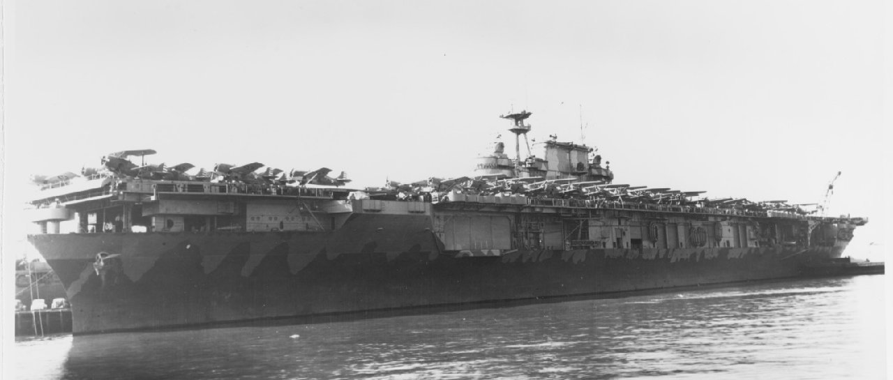
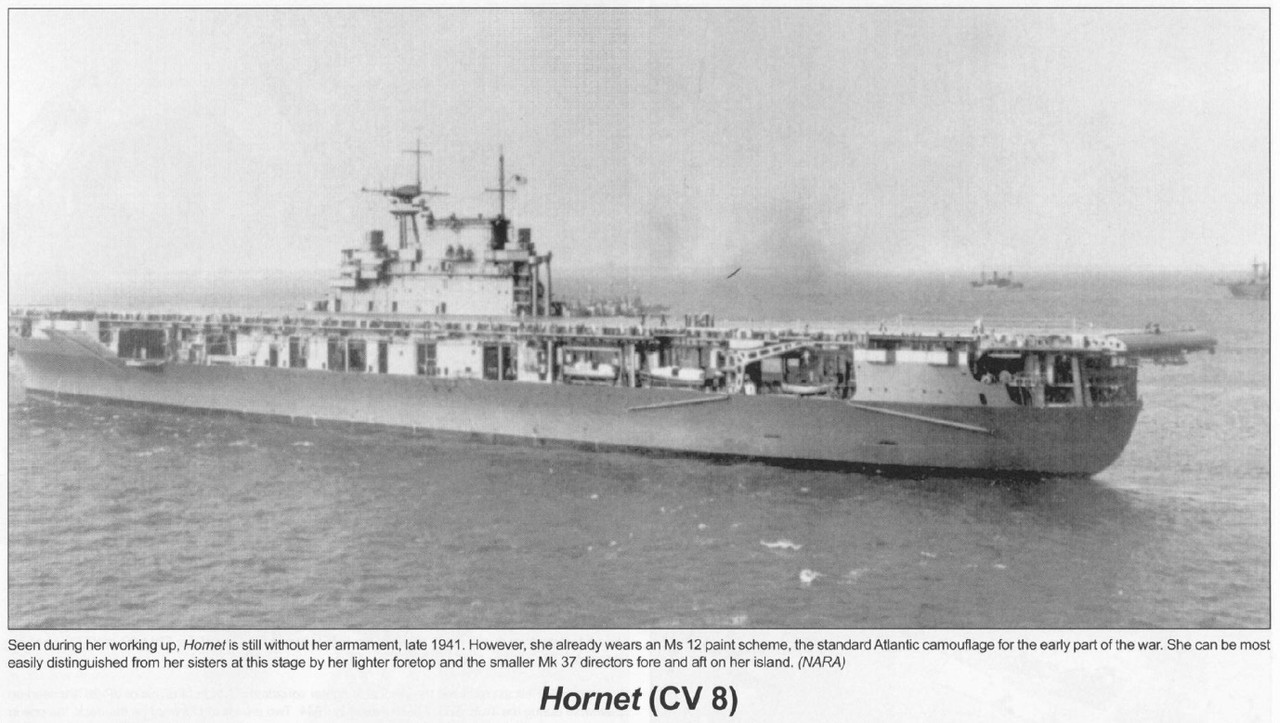
The USS Hornet (CV-8), the seventh U.S. Navy ship of that name, was a U.S. Navy Yorktown Class aircraft carrier. During the Second World War, she launched the Doolittle Raid on Tokyo and participated in the Battle of Midway and the Buin-Faisi-Tonolai Raid.
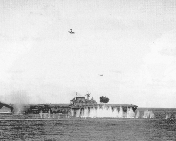
In the Solomon Islands campaign, she participated in the capture and defence of Guadalcanal and the battle of the Santa Cruz Islands where she was irretrievably damaged by enemy torpedoes and dive bombers. In the face of an approaching Japanese surface force, the Hornet was abandoned and then torpedoed and sunk by approaching Japanese destroyers.
The Hornet was in service for a year and six days and was the last aircraft carrier (CV) of the American fleet ever sunk by enemy fire. For these actions she received four stars of service, a citation for the Doolittle Raid in 1942, and her 8 Torpedo Squadron received a Presidential Unit Commendation for extraordinary heroism for the Battle of Midway. His wreck was located in late January 2019 near the Solomon Islands.
Merit stopped producing this box a year and a half ago. It's not easy to find a used one now at a reasonable price. This box is replaced by the Yorktown at Trumpeter, but there is no kit available at the moment as far as I know...
I added the MK1 kit and the MK1 wooden deck kit (also with PE inside).
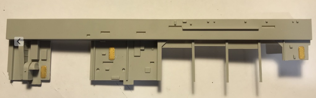
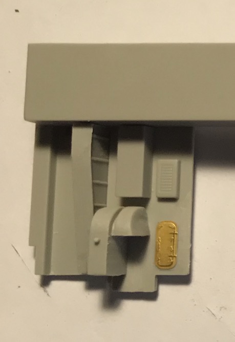
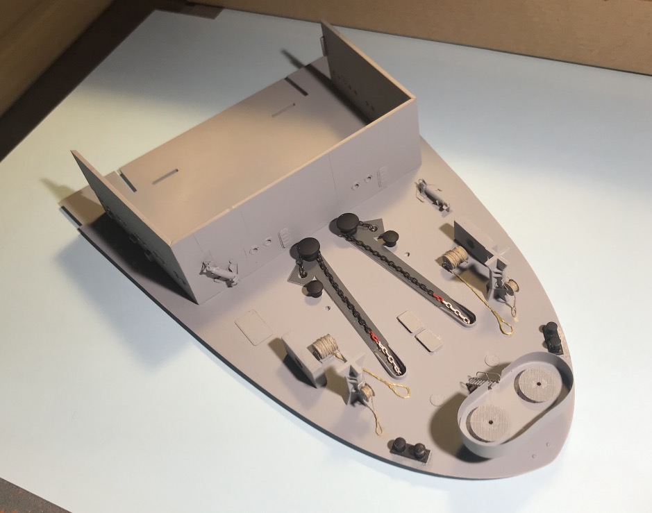
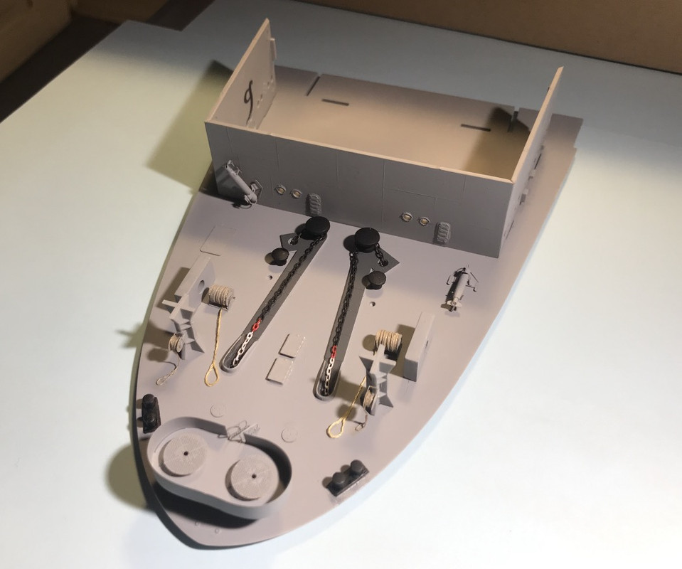
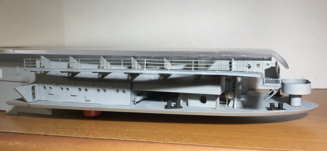
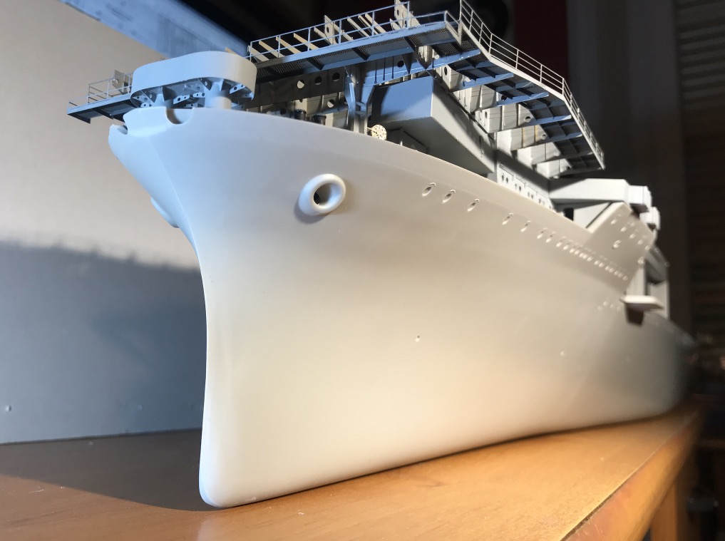
I've been working on forward for two days now.
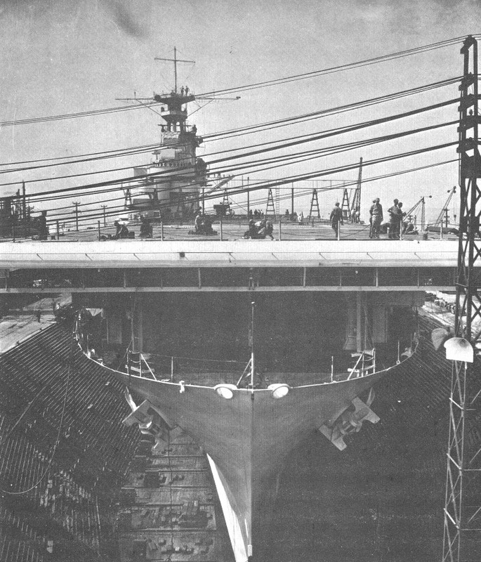
I find that there are some details missing, but the reason, at least for the foredeck (it's not really a forecastle) is probably that there are no pictures of this part of the ship to my knowledge. Only a few shots from outside can help a little. Moreover this part is under the flight deck and less visible compared to the rest.
So you have to have a little imagination...
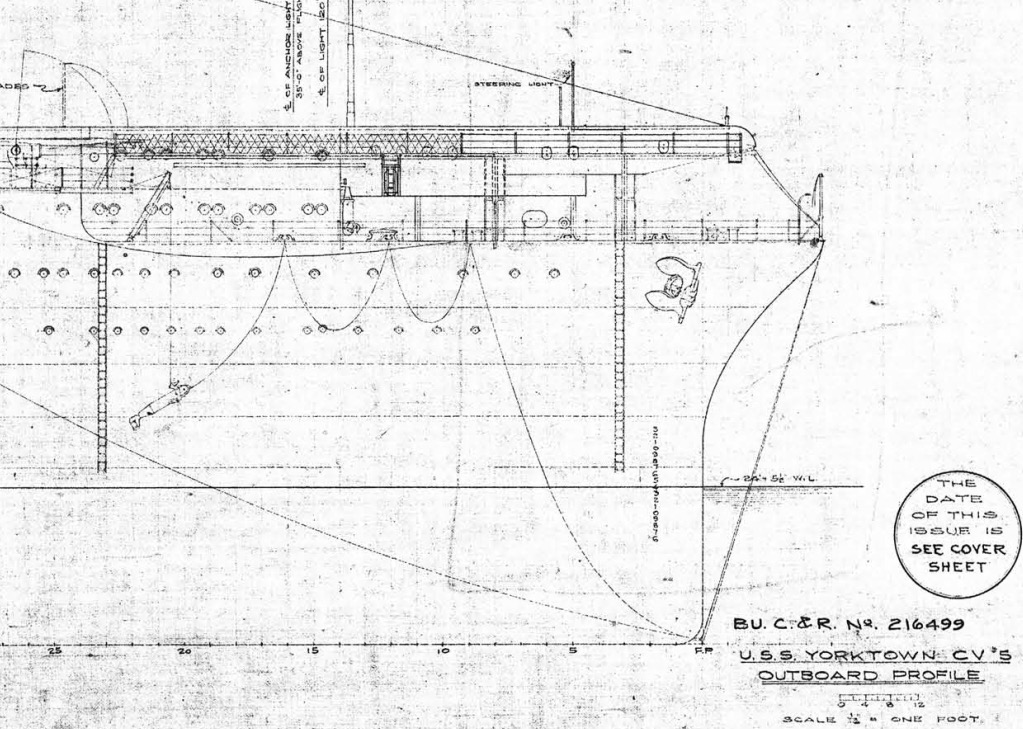
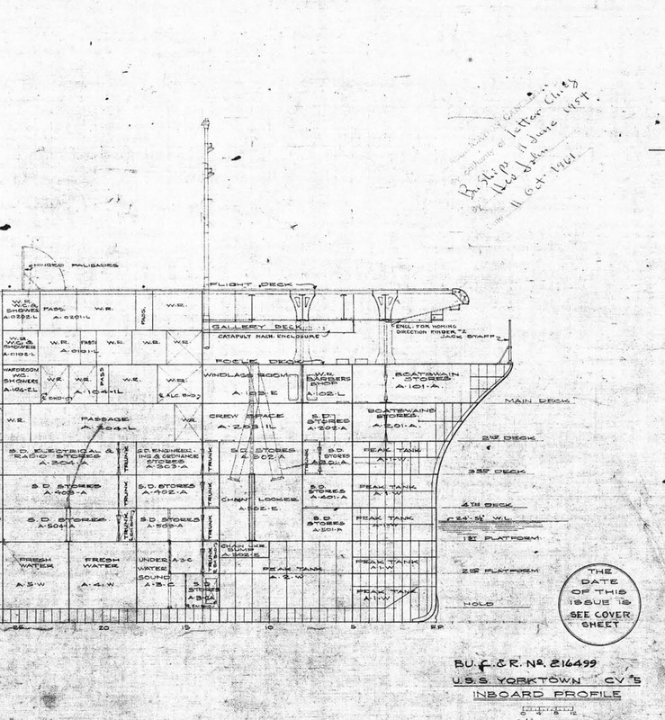
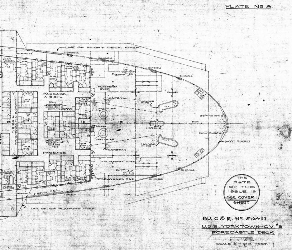
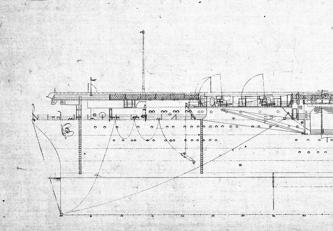
The front end of the Yorktown CV-5, not necessarily identical.
Some pictures of the progress:
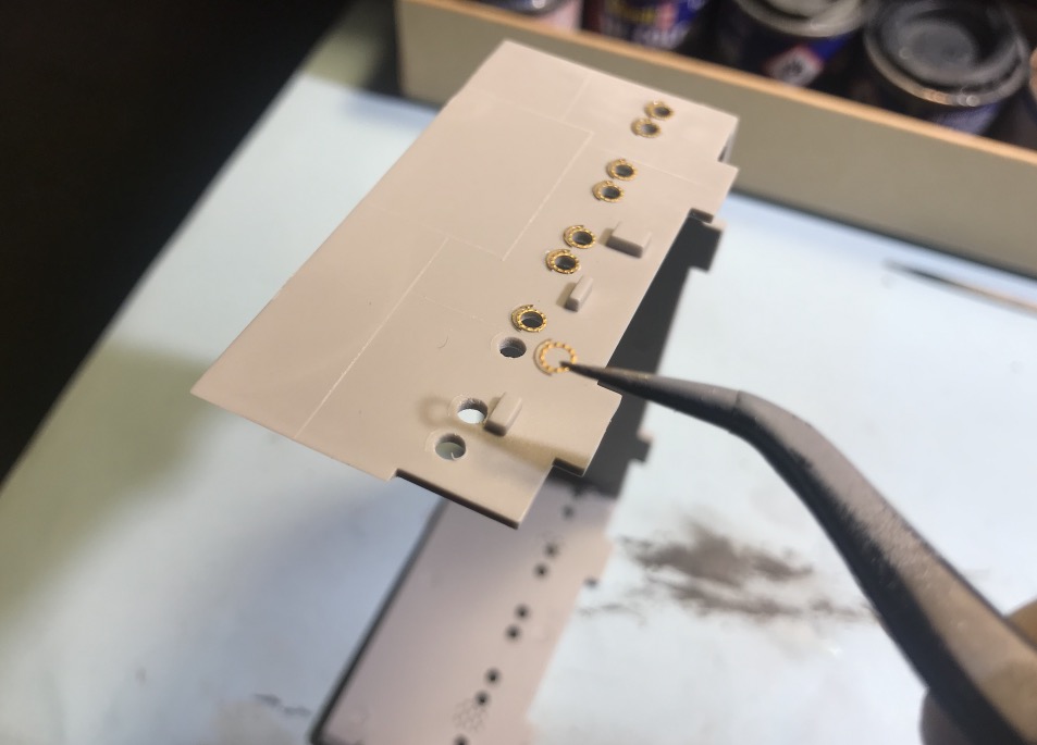
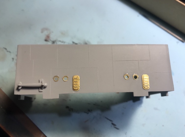
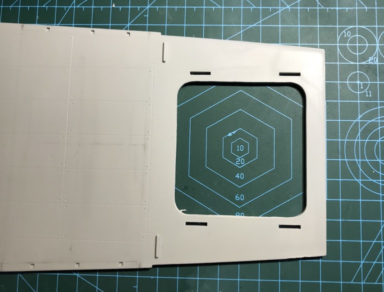
Installation of the portholes, then of a transparent rhodoïd behind.
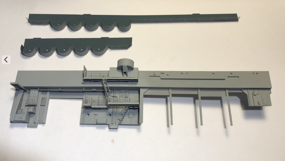
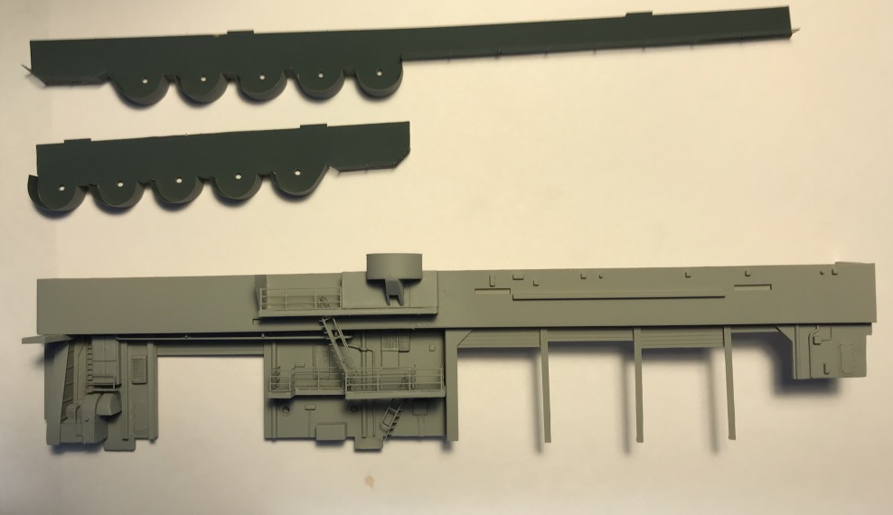
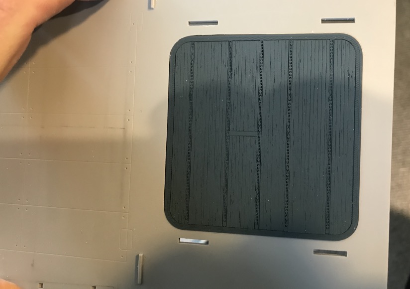
Improvement of the shingles by simulating a shingle.
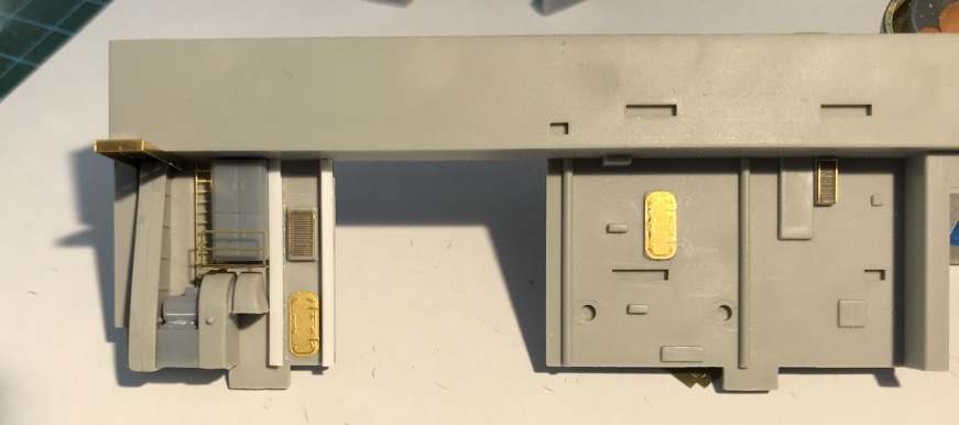
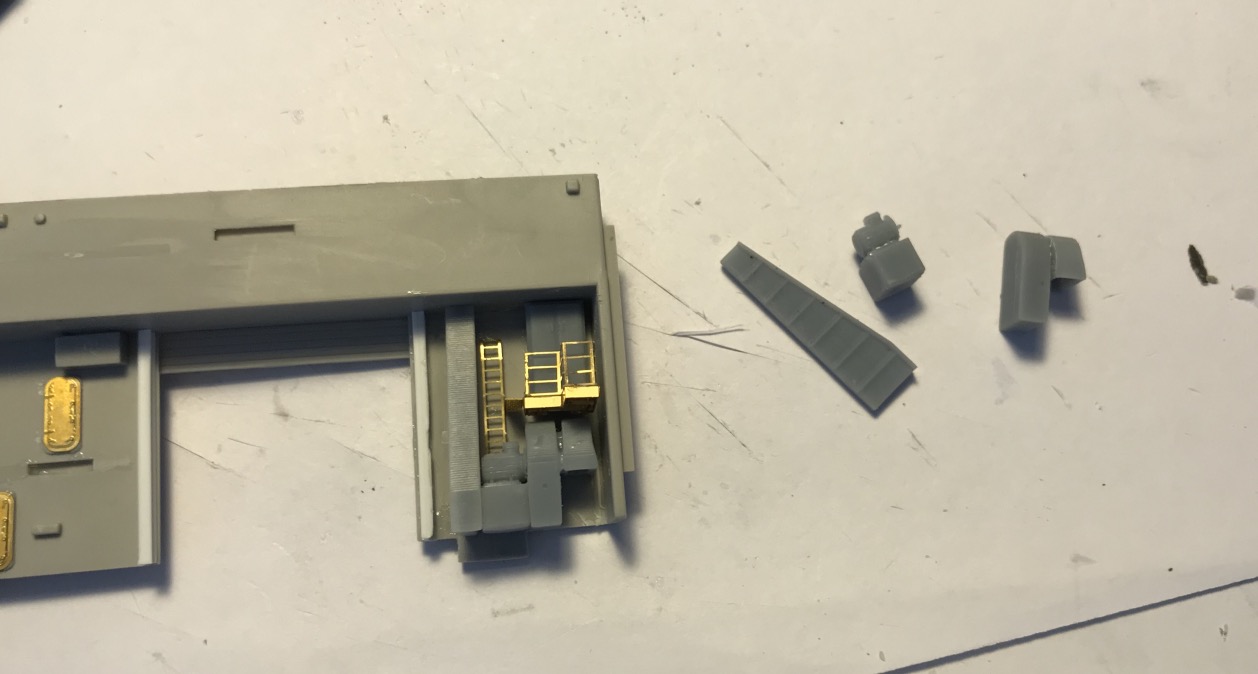
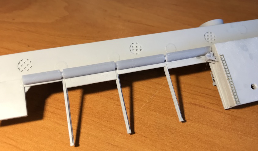
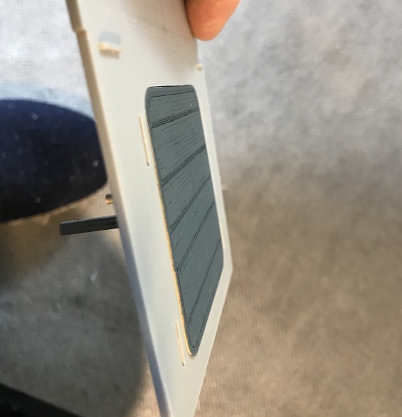
The front AA platform, the shielding is not easy to mount, it must be perfectly formed to fit .
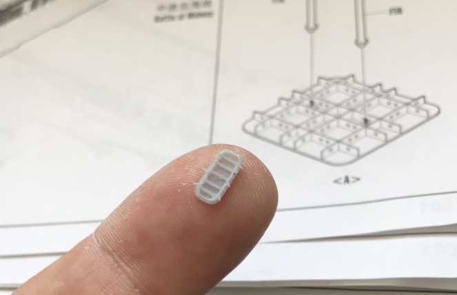
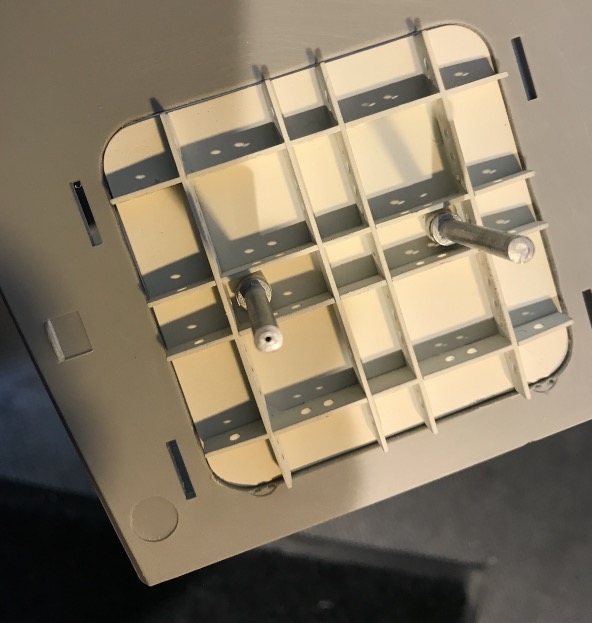
I've added two small lattice platforms for the cannons. I also added a ladder because nothing is planned at Merit to go up there... Luckily, I still have some of Bismarck..
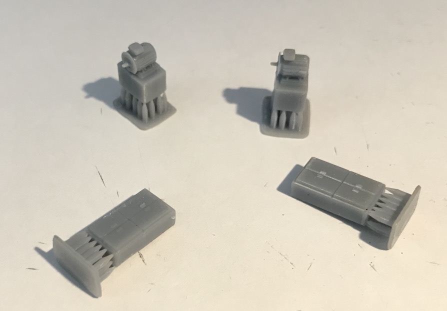
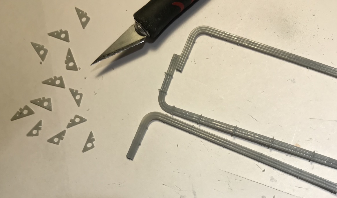
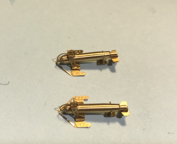
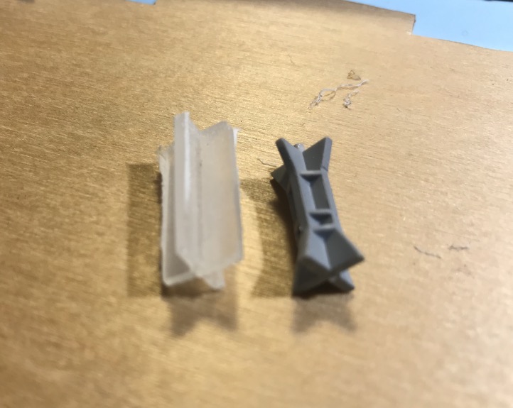
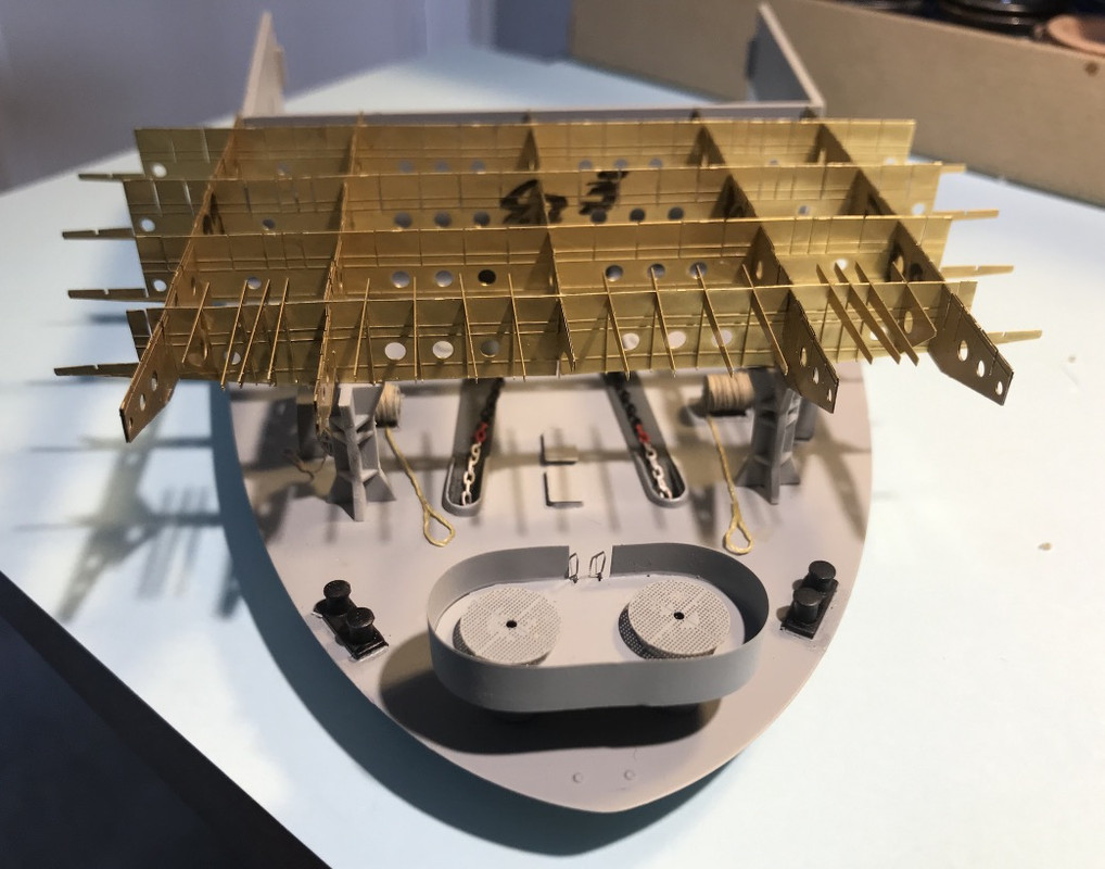
The two front paravanes. I counted 9 pieces for one..
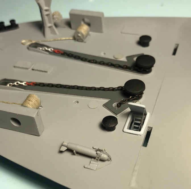
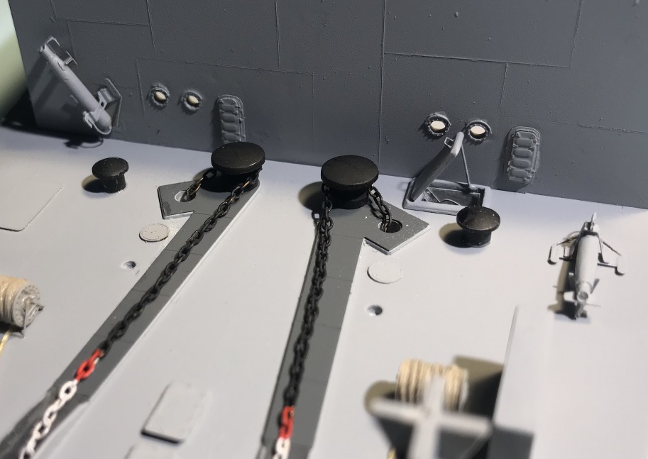
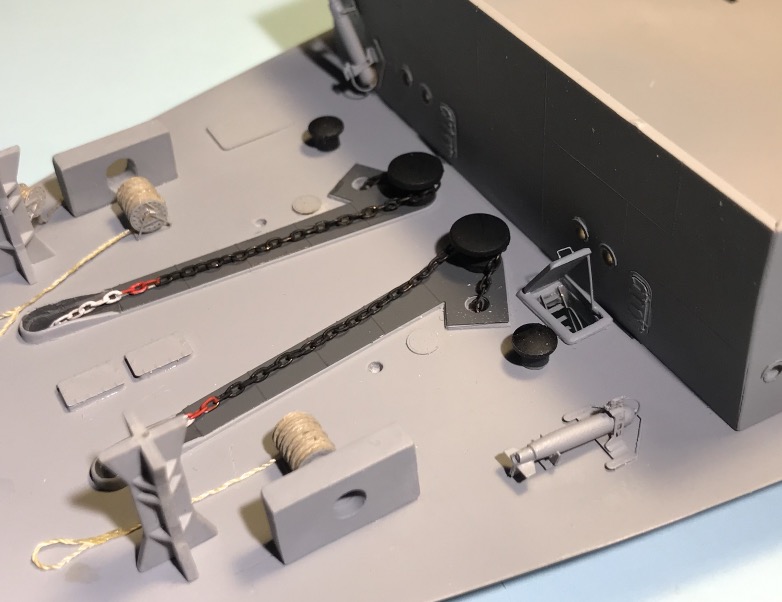
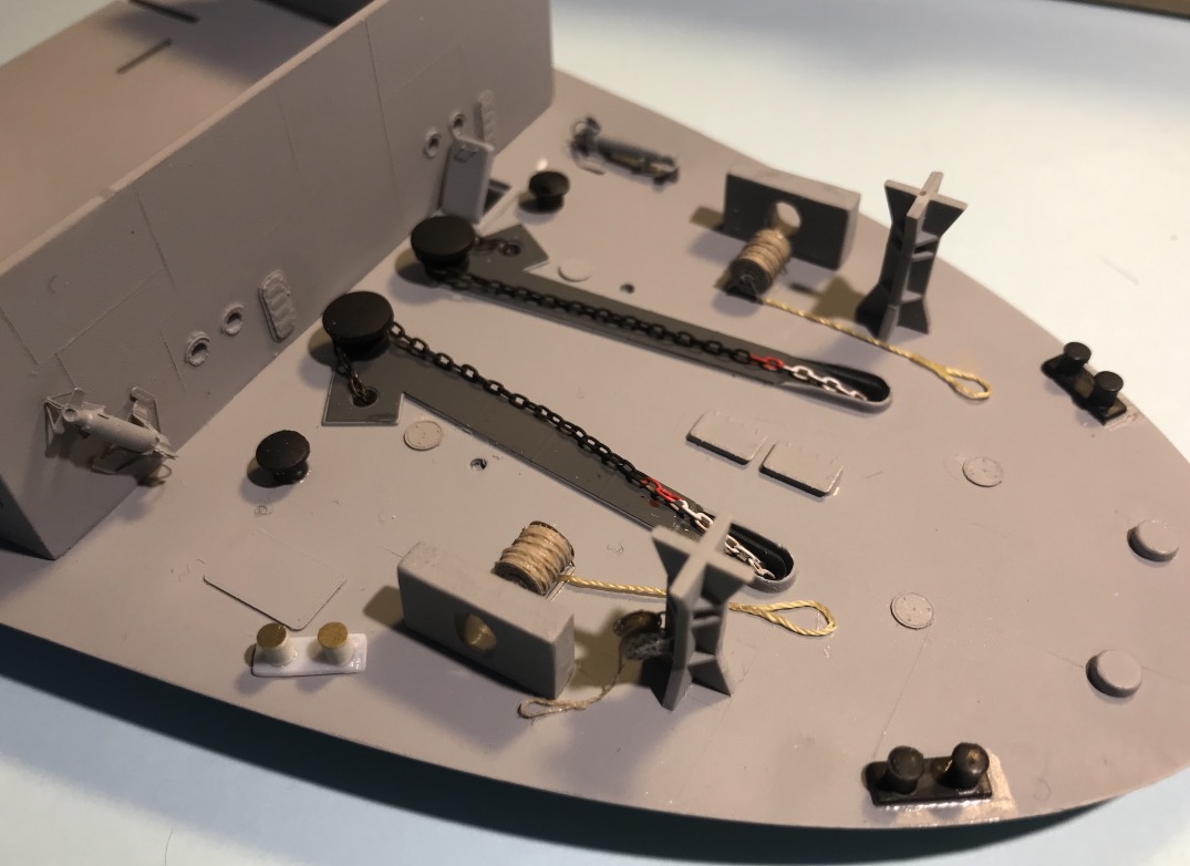
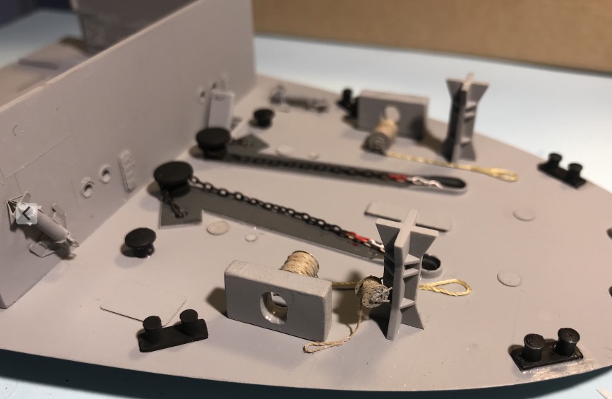
I've added some access hatches on the deck. I have also reproduced the soldering lines of the deck and the forward block with the cutter. The port door has since been straightened.
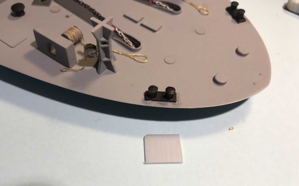
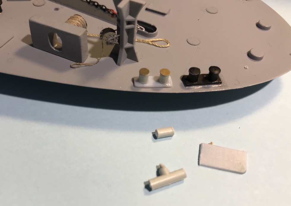
I don't know what the two holes in the deck near the capstans are for, a mystery, I'll hide them with an access plate probably...
I still have the anchor lashings to install. (Scratch)
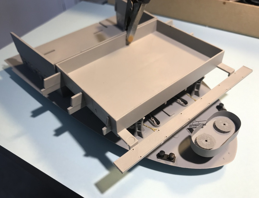
Compared to the plan of the Yorktown, two mooring bollards are missing on the rear of the manoeuvring range. Merit ship must never dock... There's scratch in the air...
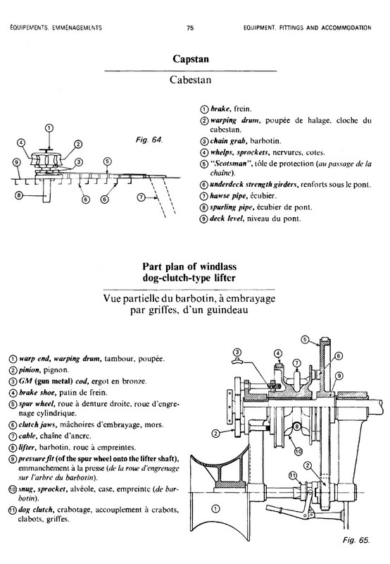
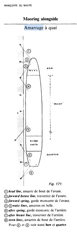
A little reminder of the marine terms used especially on the guys. This book has followed me throughout my maritime career... A gold mine.
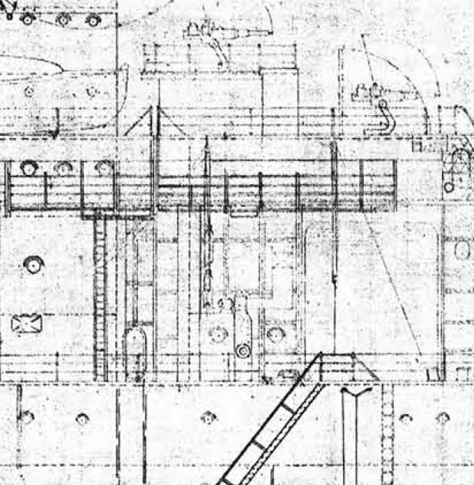
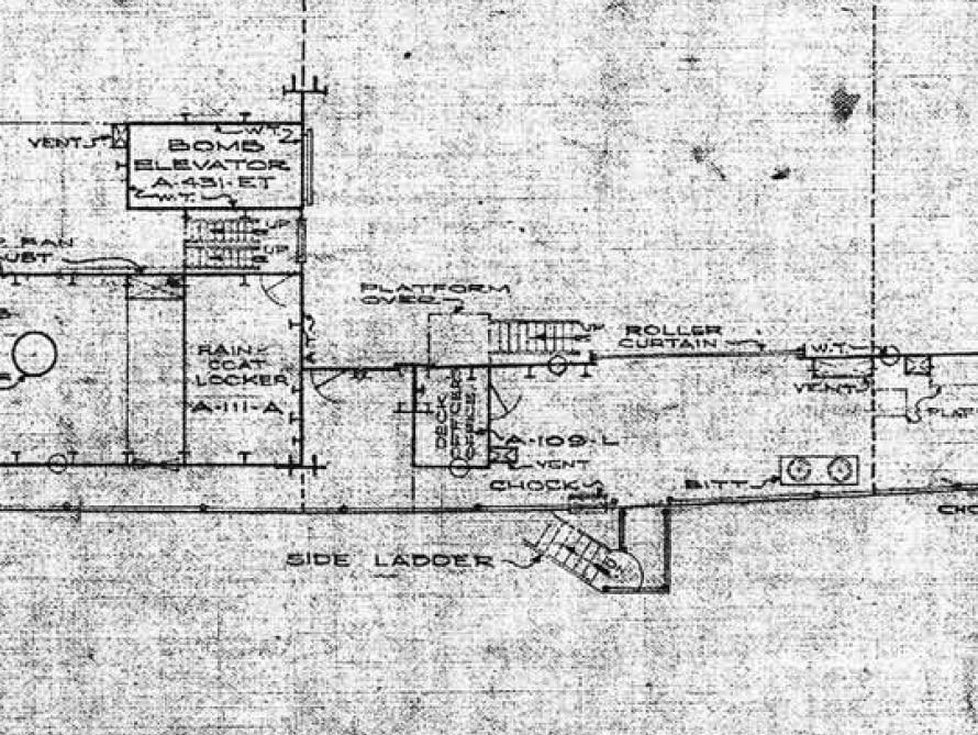
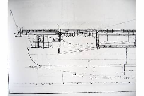
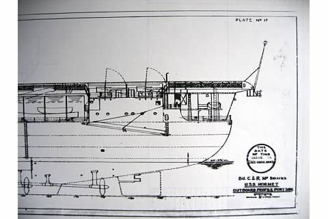
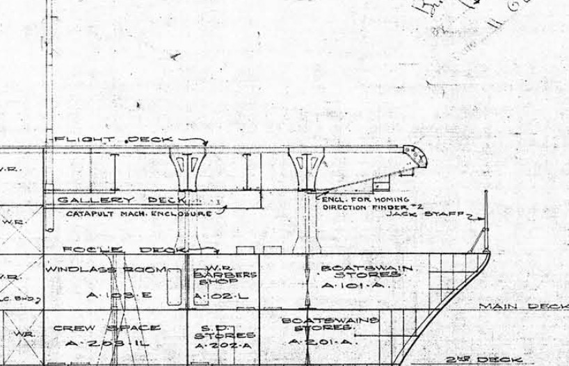
This morning's work still on the plans of the forward deck of the Yorktown CV-5, the only reliable source, but not without flaws because changes have been made to the CV-8, as on all sister ships by the way, even in the merchant, I speak with full knowledge of the facts....
I can see some details:
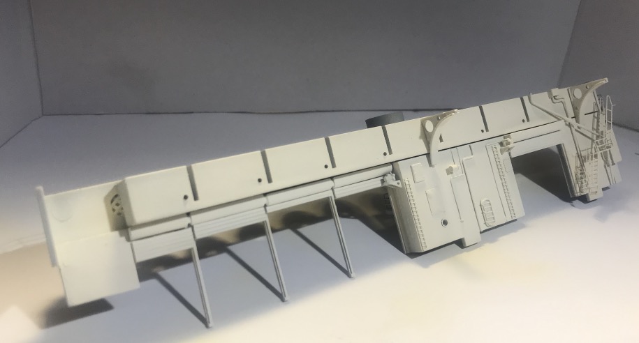
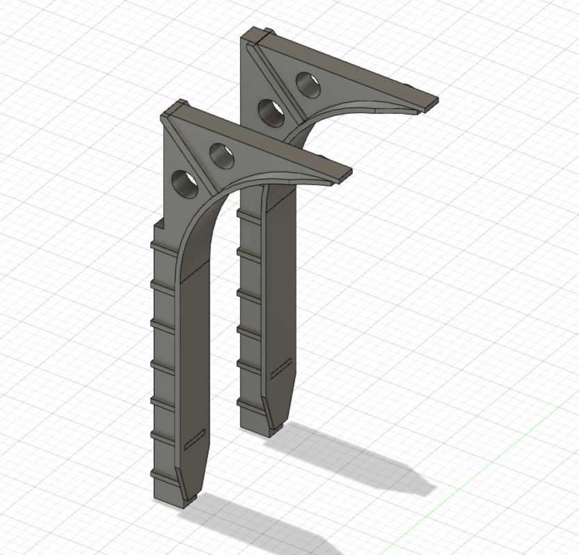
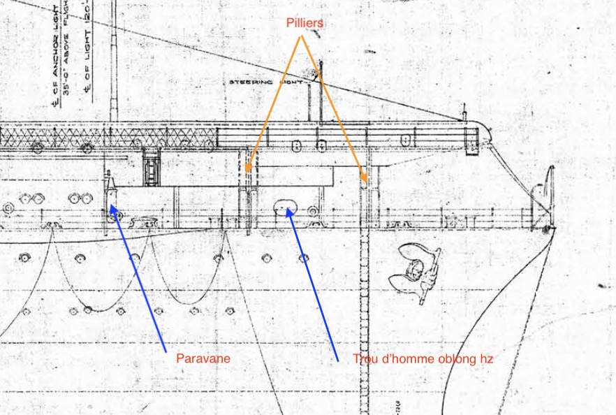
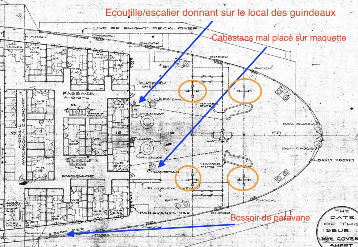
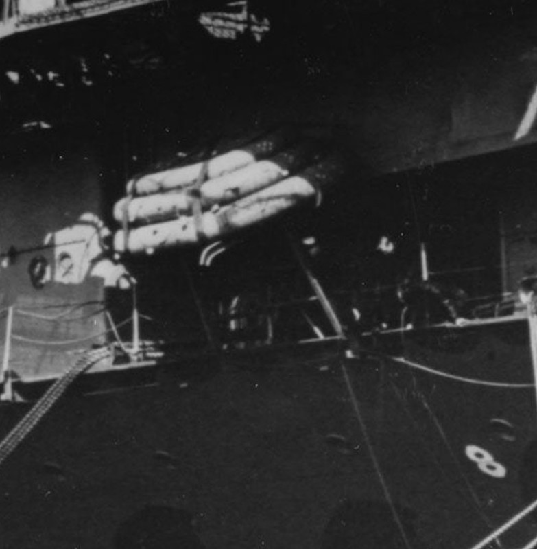
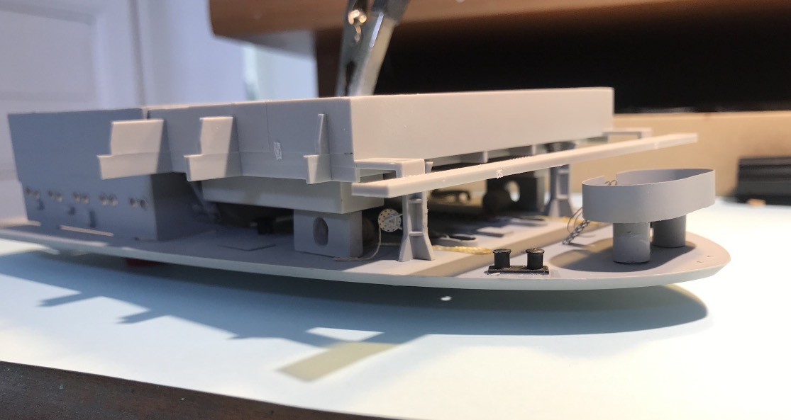
- The two paravane davits to be added. - Move the two capstans that are not in the right place. It can be done. - Adding a hatch that allowed access to the technical room for the windlasses and capstans below deck is still feasible. To be seen. - It normally has 4 pillars supporting the flight deck, 2 are only shown on the model. I don't think it has been modified between the two APs. I have to dig to see if I can add them because the structure under the flight deck is made of PE in my version... - The paravanes seem to be in the right place except for the port side which is on the deck, I would take the opportunity to put sailors around it as if they were moving it to the davit bd... It seems difficult to take it off now. - On the CV-5 the oblong manholes of the catapult room supports are horizontal, on the CV-6 they are vertical, see photo and plan, on the model it's round, I'll have to modify them. - There are 3 rafts stacked on a sleepway on the front of each edge that doesn't seem to be represented on the model, but not in place in april 1942.
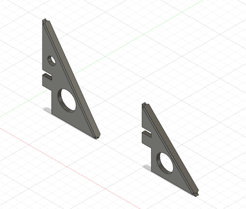
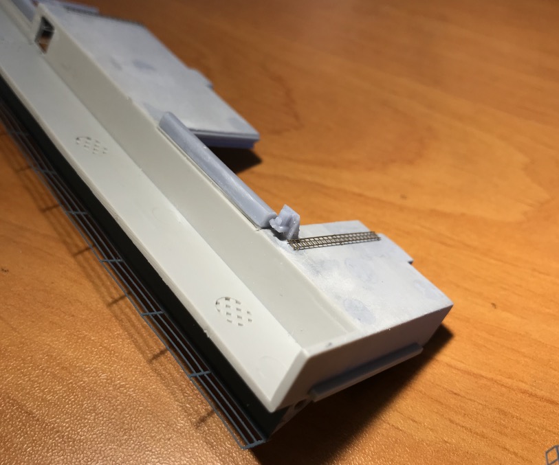
Paravane davit (Simple boom).
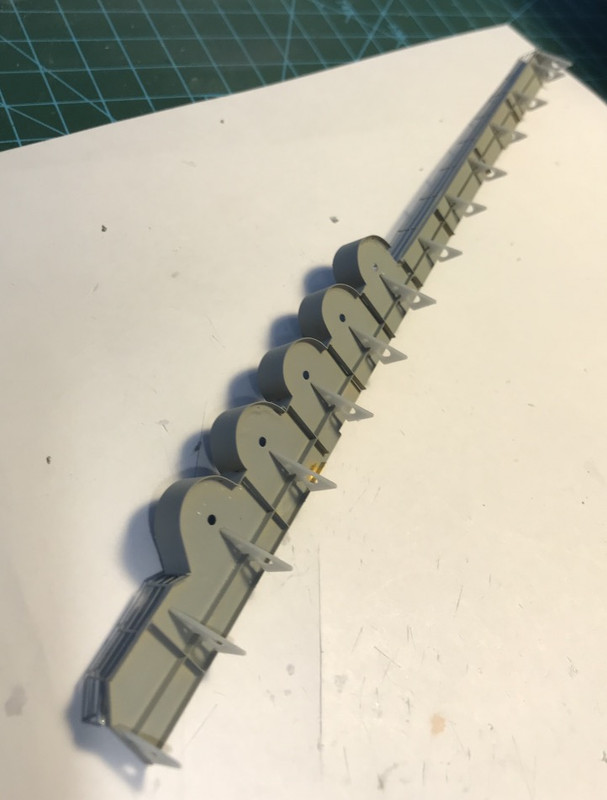
Rafts.
Slotted manhole in the rack.
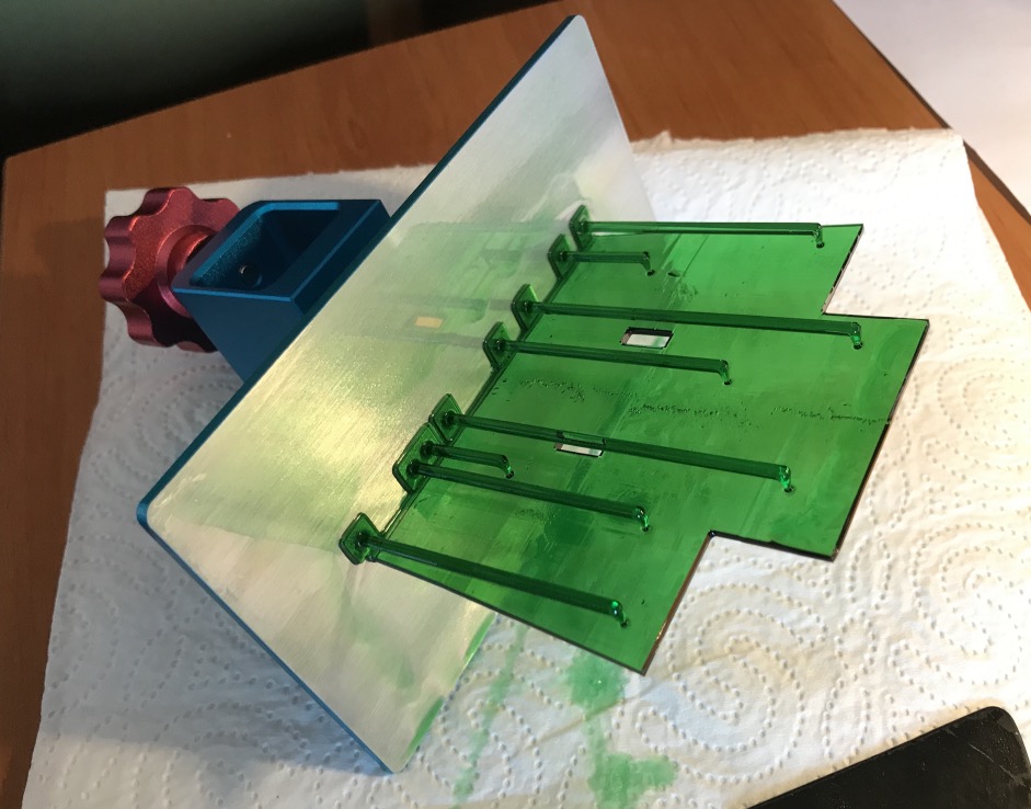
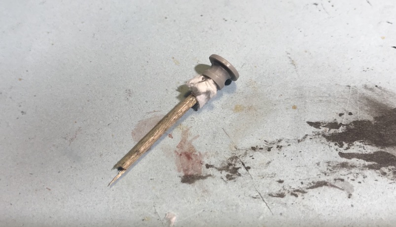
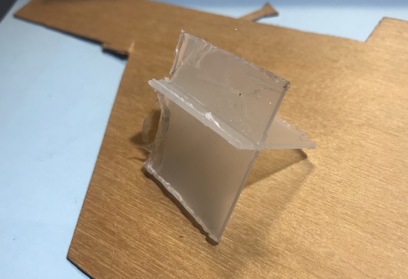
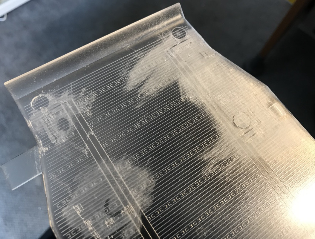
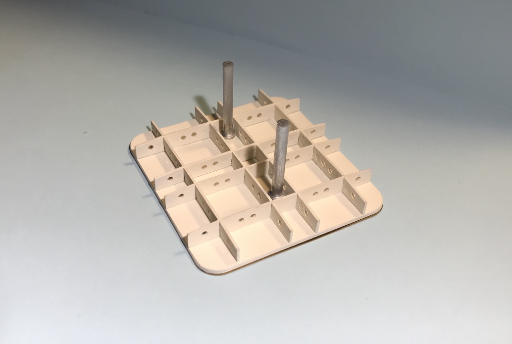
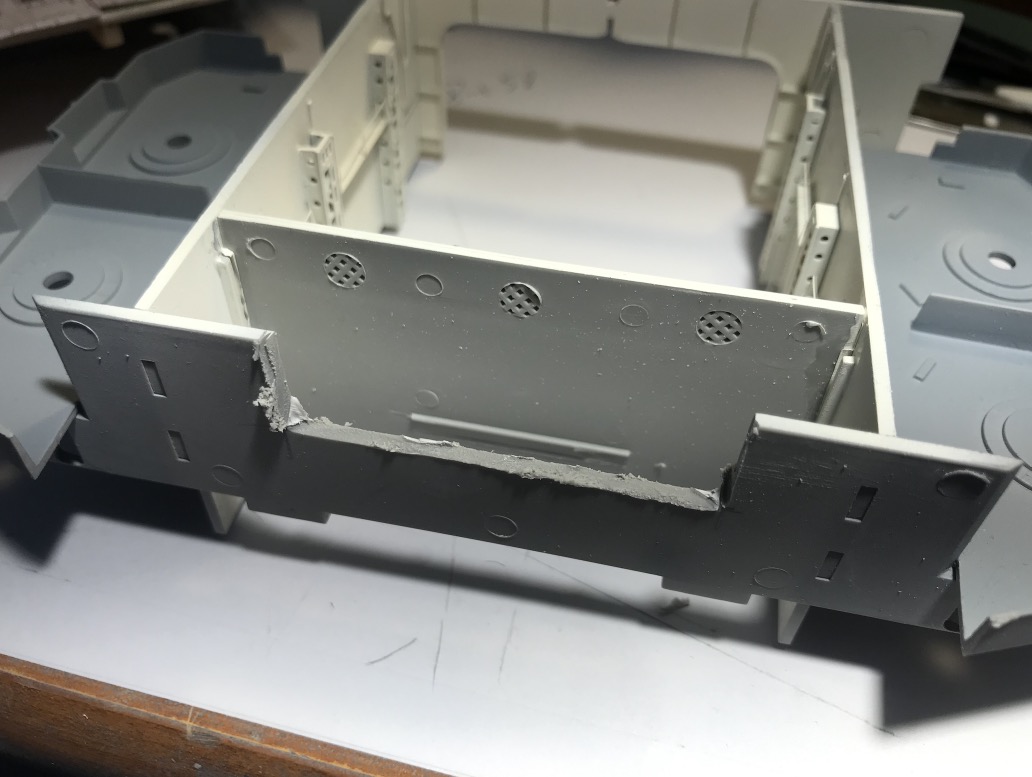
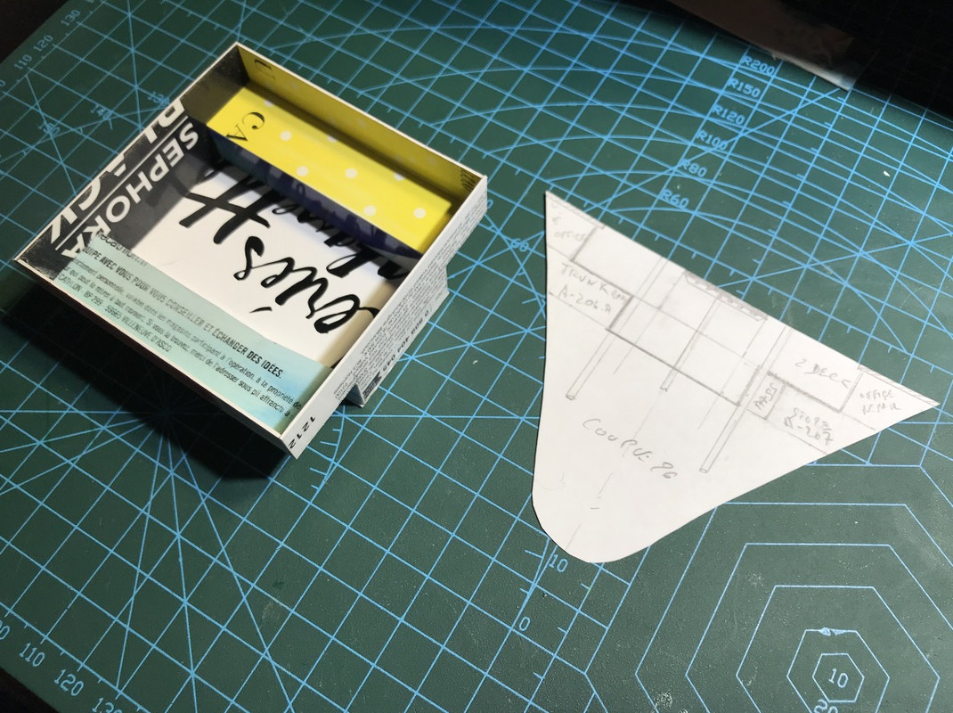
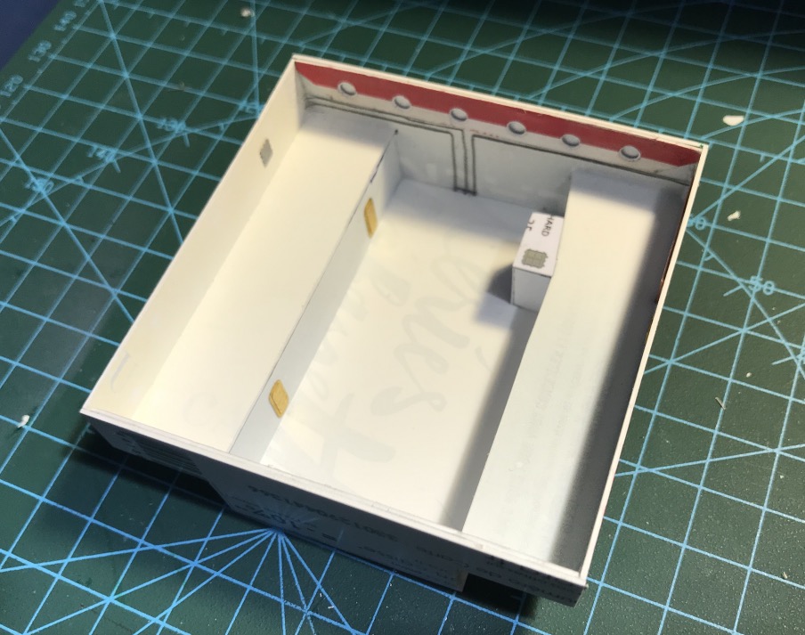
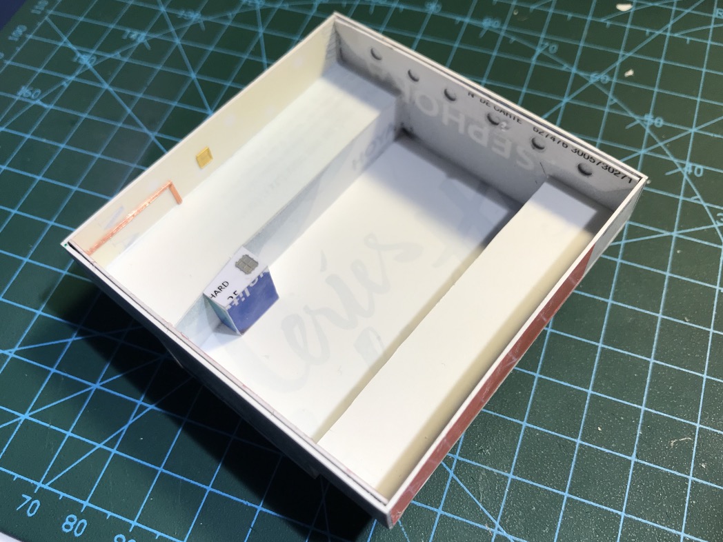
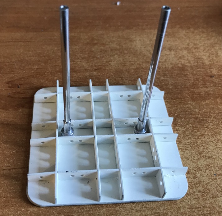
Well, I've been looking for an hour to figure out how to make the two missing pillars of the flight deck. And then little by little I found the object that could help me to make this crosspiece. I set my heart on a plastic screw storage box that I had in my mess. The thickness of the partitions is the same.
Cutting from the box with a blowtorch-heated box cutter, it breaks through that crystal plastic pretty fast, even if it's a little soft.
I'm making a rough draft with the Dremel's circular saw:
The rest I do with a burr that's fine, and a little surgical scalpel (I was given a big, expired packet of them).
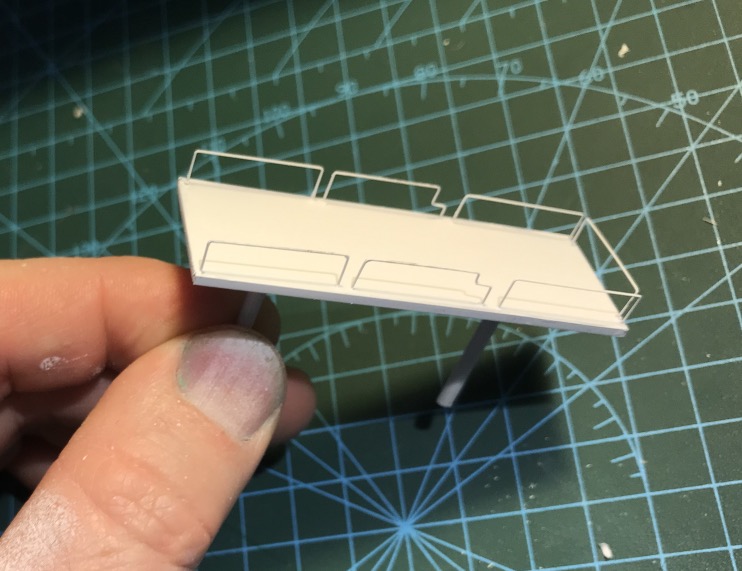
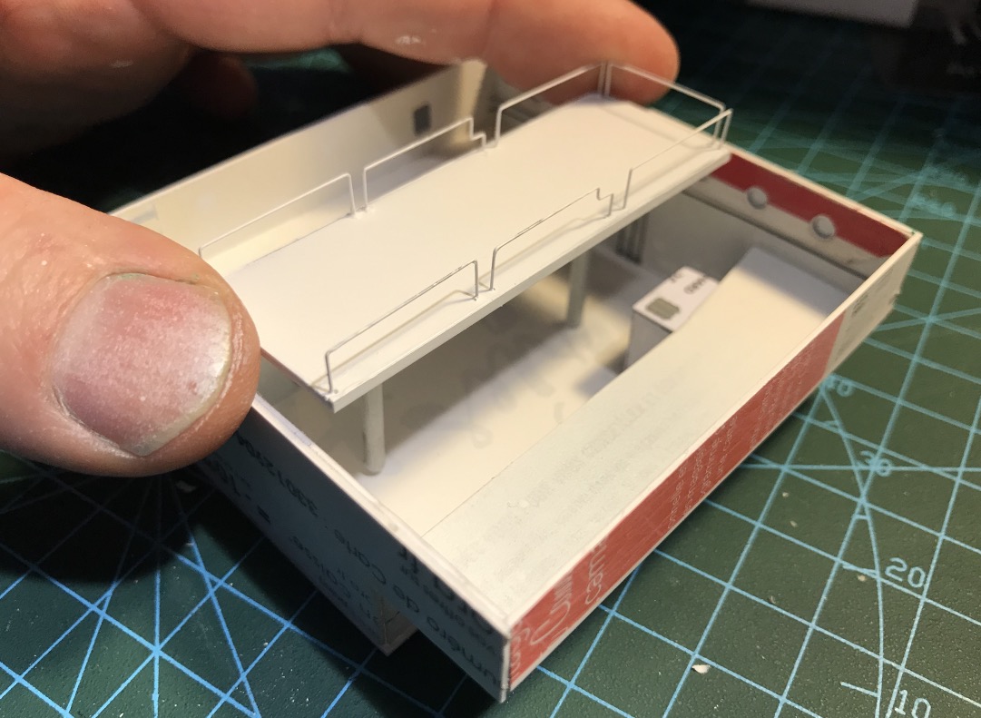
Now I have to glue a little bit of PE sheet, cut with scissors, to make the stiffeners, an airbrush stroke, and then make a second one...
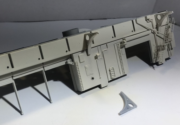
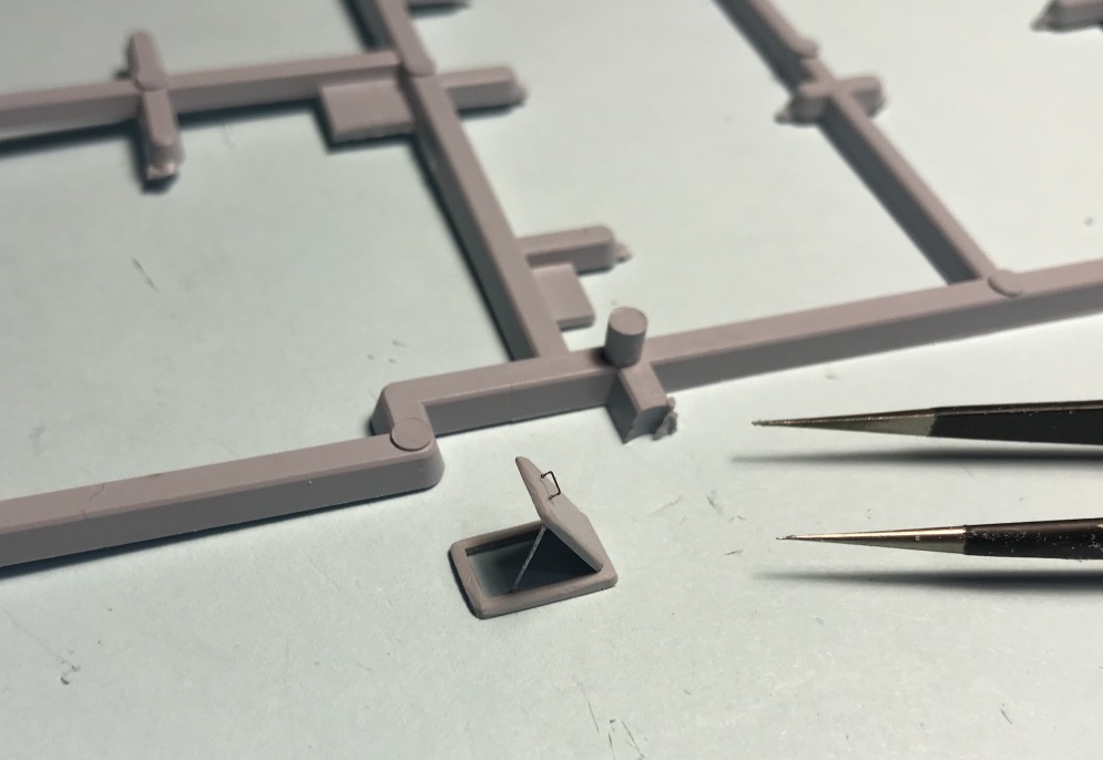
Manufacture of the missing hatch, with its staircase.
The plastic is from a Heller cluster, engraved cluster number plates in fact. I still have a few welded ladder rungs left, and that's it! I have a few 1/200 ladder/stairs in reserve too.
Two mooring bollards still need to be made.
Then, of course, all this will be partly masked by the flight deck structure.
I say to myself, here, I'll take it easy, it should have been a pleasure, no apparent difficulties...
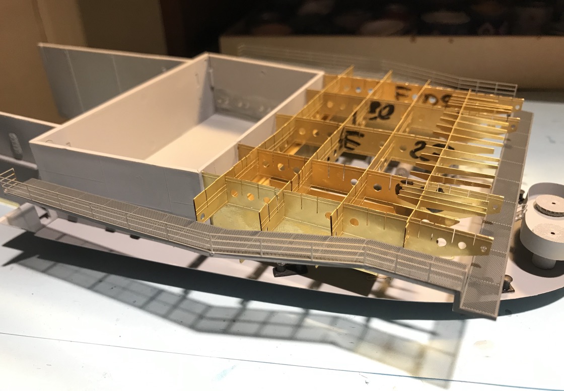
But no, if I had the ectoplasm that designed this EP drawing, I could make him eat it!
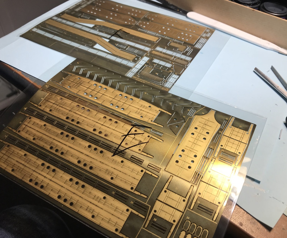
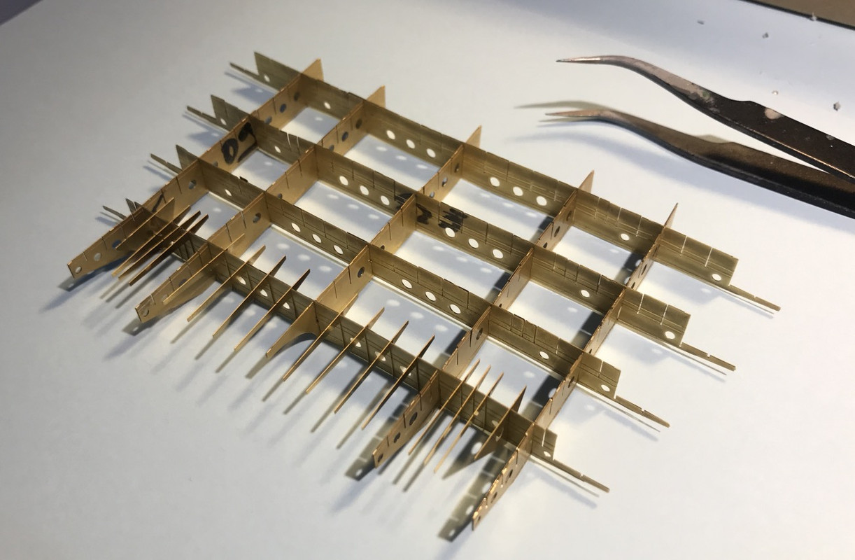
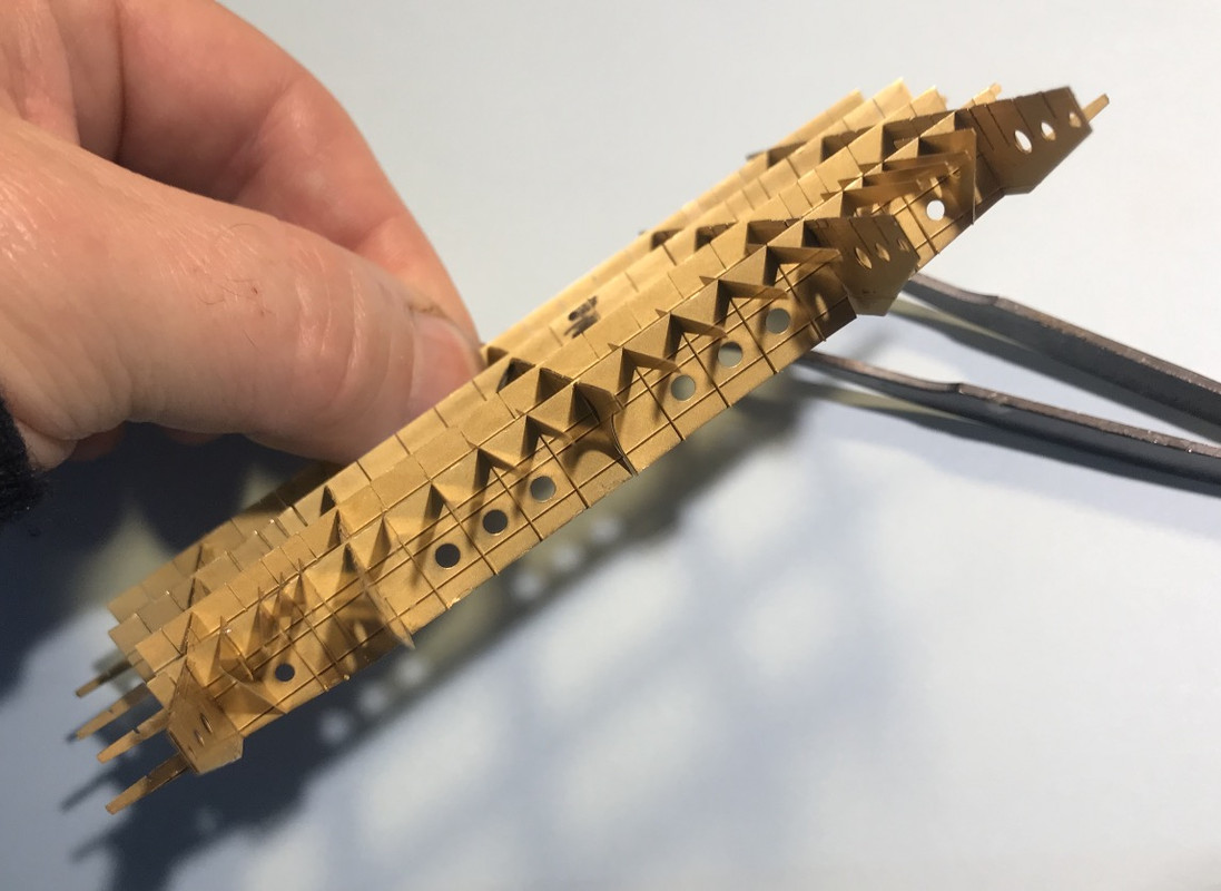
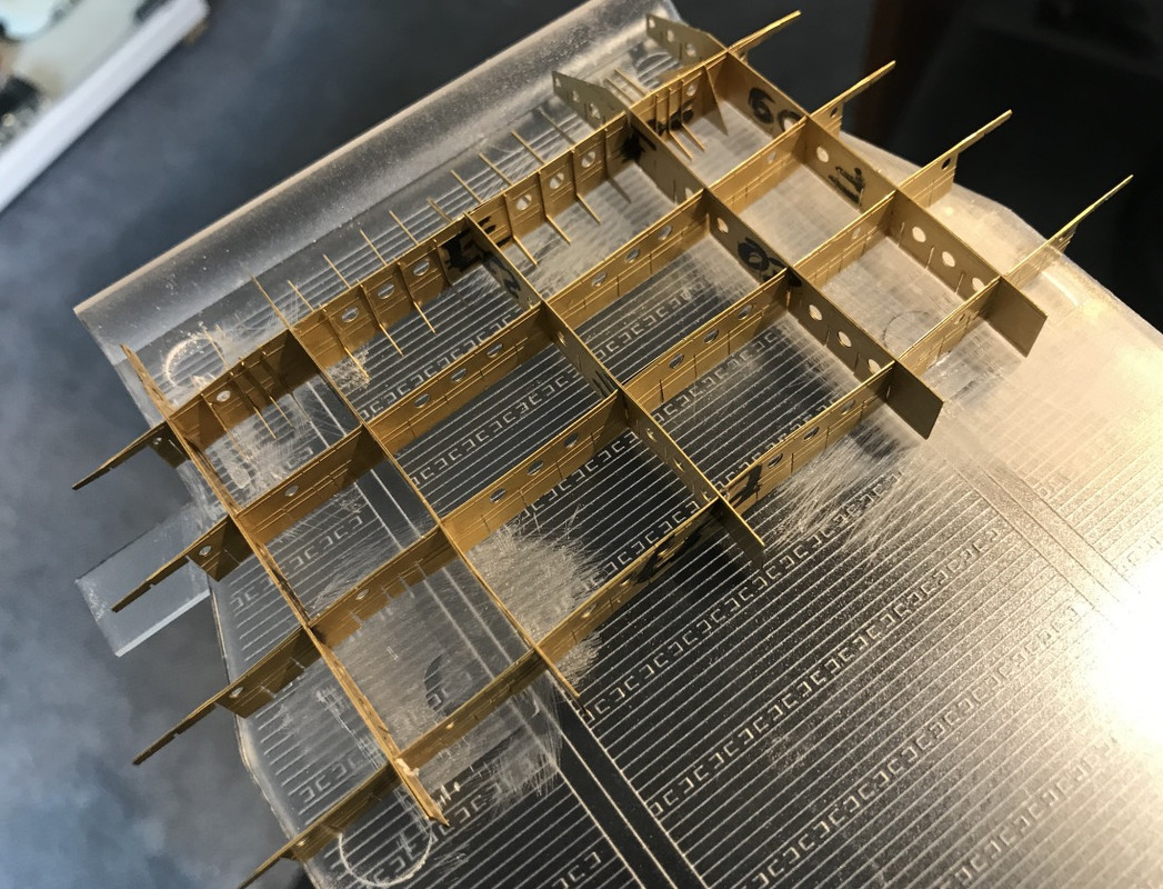
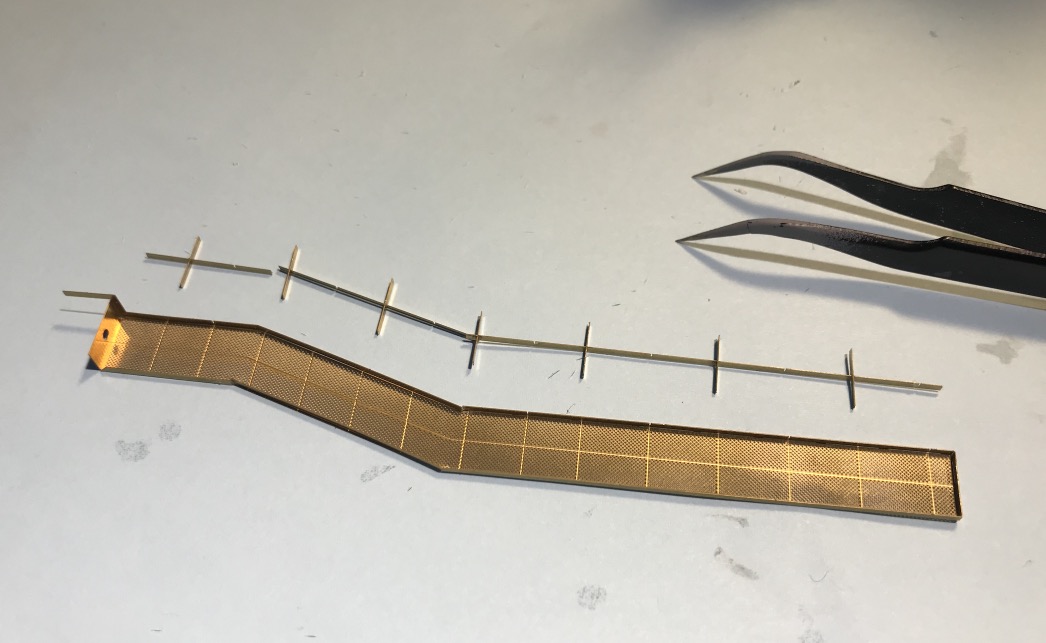
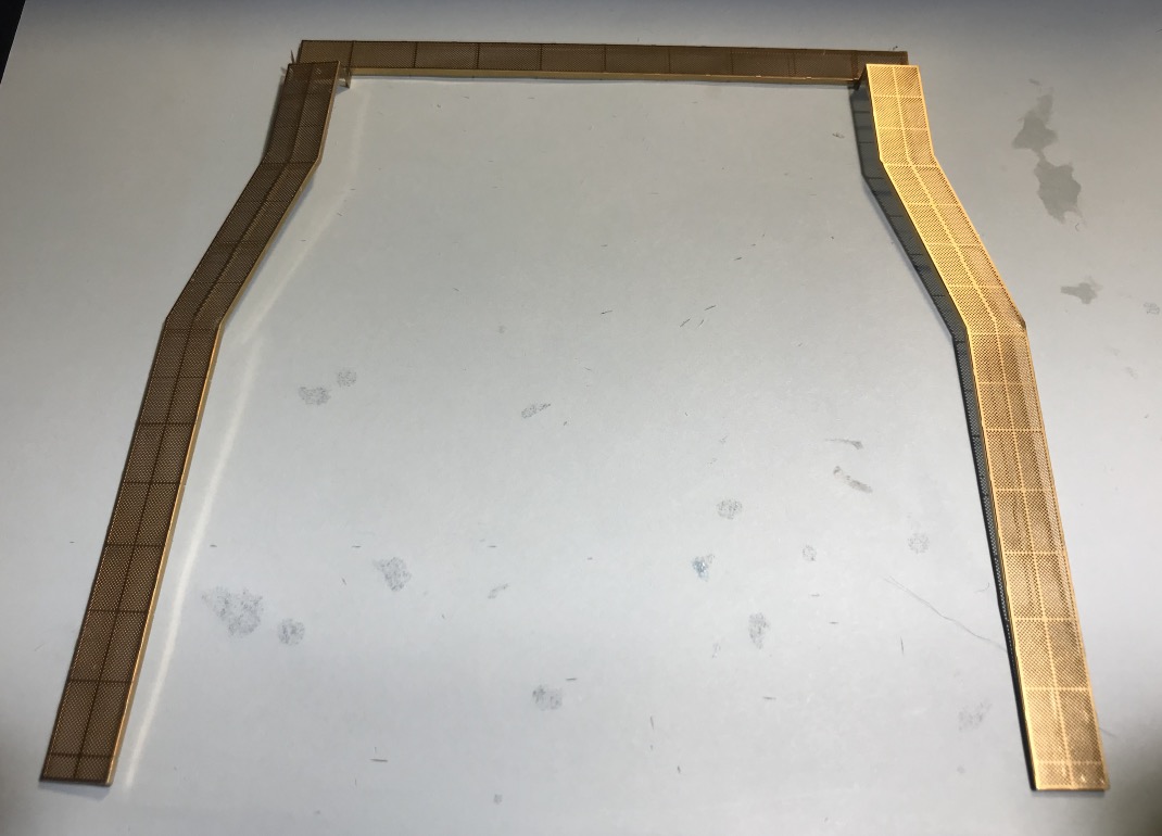
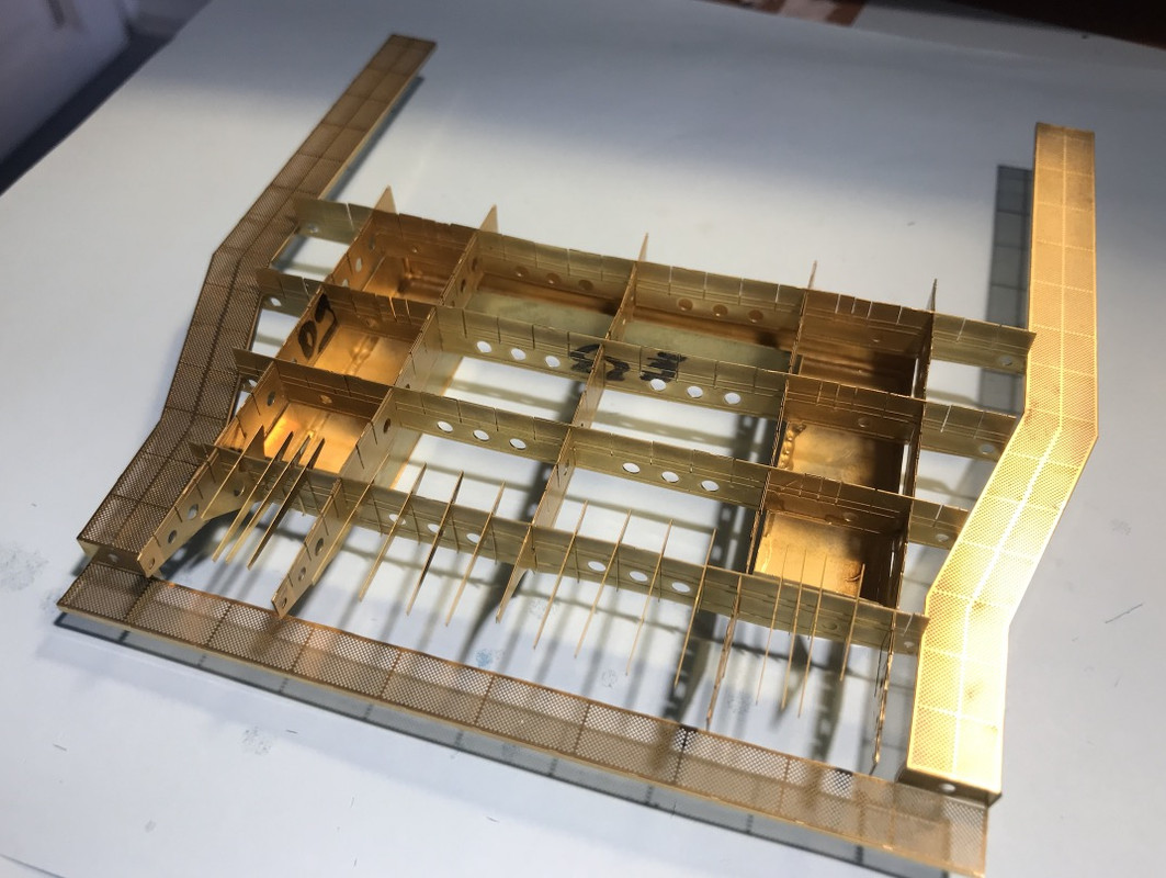
Anyway, once the two parts of each beam are bent on itself, it doesn't fit very well into each other at intersections, I still go on thinking naively that it will stiffen, but I don't assemble any more, the whole chassis won't twist anymore. Forced to take everything apart and re-number it, I hadn't glued anything together by chance.
The fact is that the assembly slots are not wide enough, the guy who designed it didn't think that the beams were twice as thick. Stress causes everything to twist.
So I had to cut all the slots with small scissors, over 40, thanks Fiskars scissors!
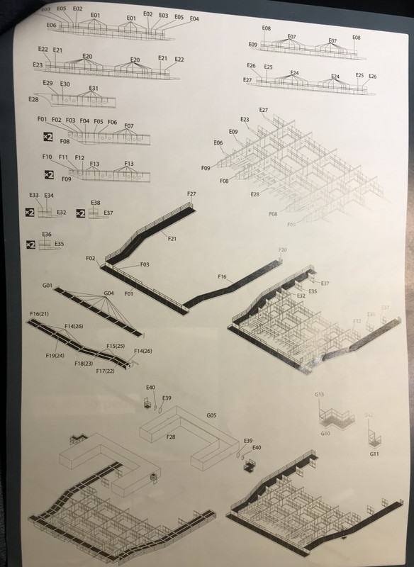
The final result presented on the notice.
The assembly plan.
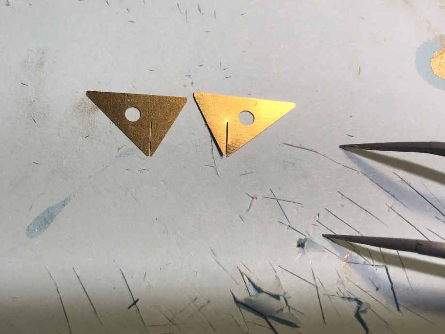
An example of a scissor cut element.
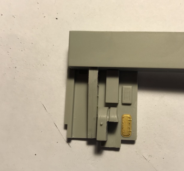
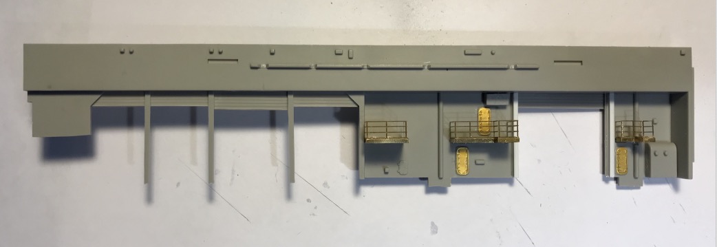
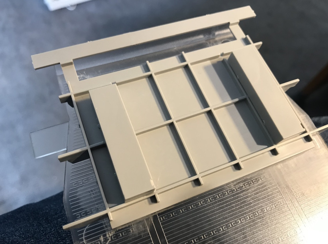
The plastic part, which is replaced by PE, is not a picture in terms of aesthetics. Fixing points under the flight deck have to be removed.
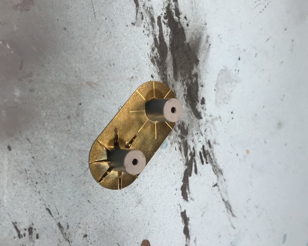
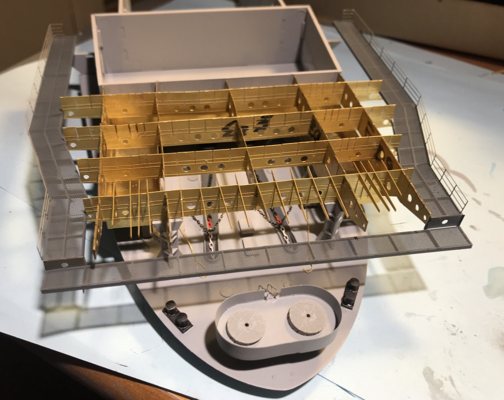
Manufacture of the 2 mooring bollards, they are used to "turn" a forward spring or possibly a breast line.
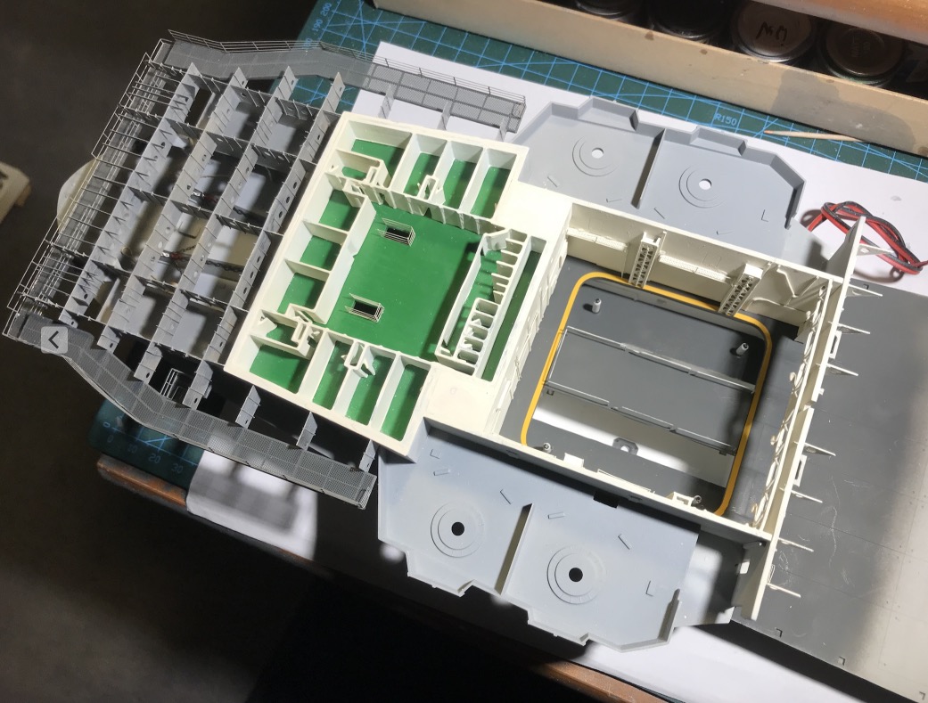
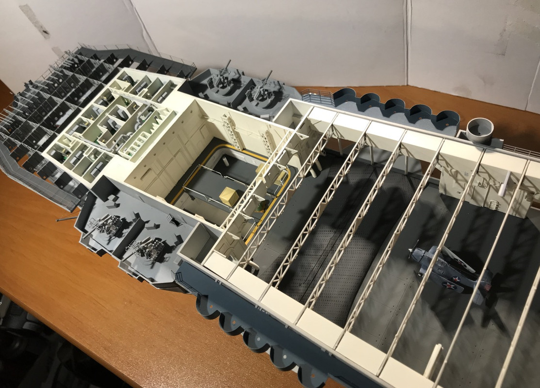
The catapult room is in place. Remaining to mount the gangways around it.
The pillar I made was cut in two, half a length is necessary because they are under the catapult room.
I took off the starboard paravane again because it didn't fit with the PE. I positioned it Hz to finish.
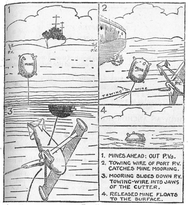
A paravane is a device used to protect a ship from sea mines or submarines, consisting of a towing cable and sometimes equipped with explosive charges, used mainly during the First World War. It can cut the cable of a mine.
The paravane, a form of towed submarine "glider", was developed in the United Kingdom between 1914 and 1916 by Commander Usborne and Lieutenant Burney of the Royal Navy and financed by Sir George White, founder of the Bristol Aeroplane Company.
Initially developed to destroy naval mines, the paravane was towed from the towing ship. The wings of the paravane force it to move away from the ship while tensioning the towing cable. In this way, the paravane's cable hooks the mine's anchor cable, breaks it and allows the mine to rise to the surface where it can be destroyed by machine gun fire. If the mine anchor cable does not break, the mine explodes safely against the paravane. The cable can then be retrieved to put another paravane back into the water.
A paravane, loaded with TNT, has also been developed to be used as an anti-submarine weapon during high-speed area sweeping. The towing cable, which is armoured and electric, is activated manually if the submarine does not automatically unhook the paravane. (Wiki)
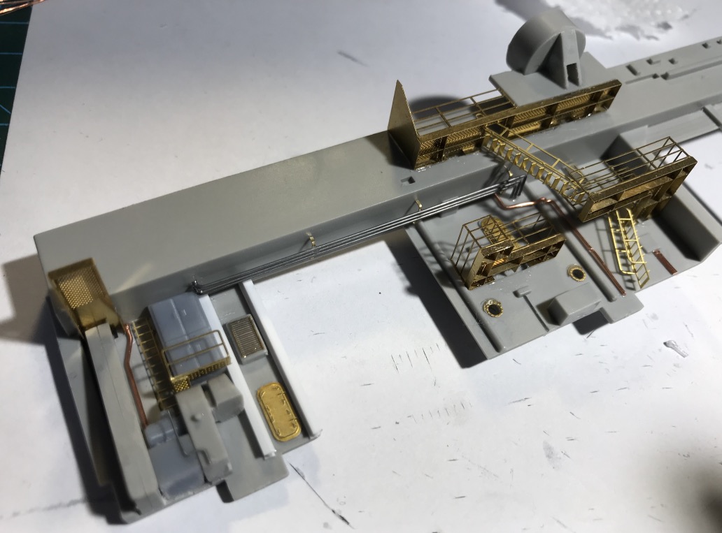
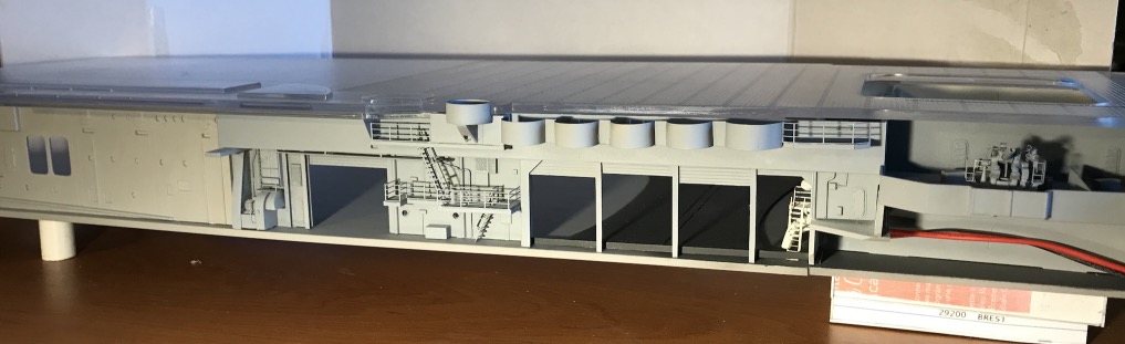
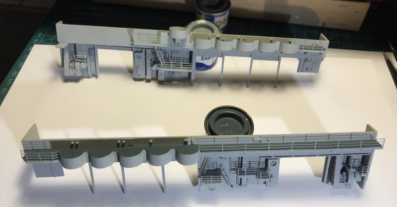
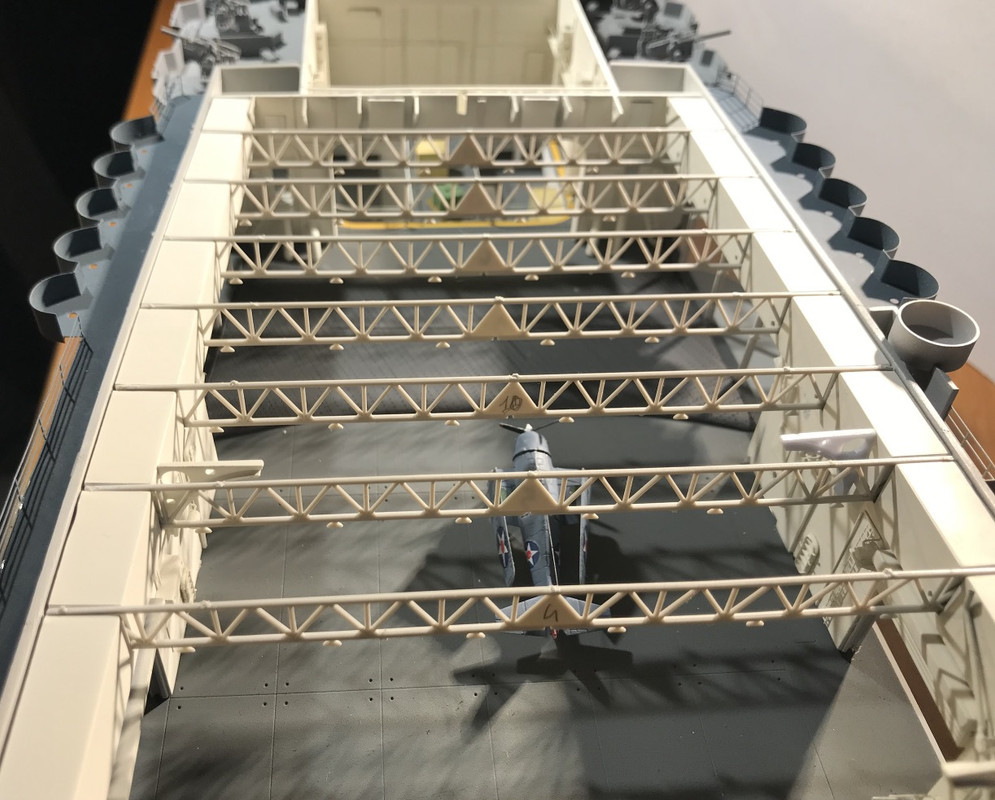
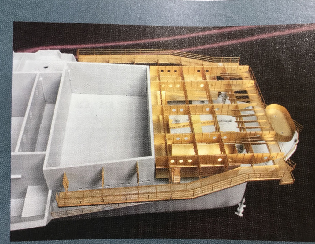
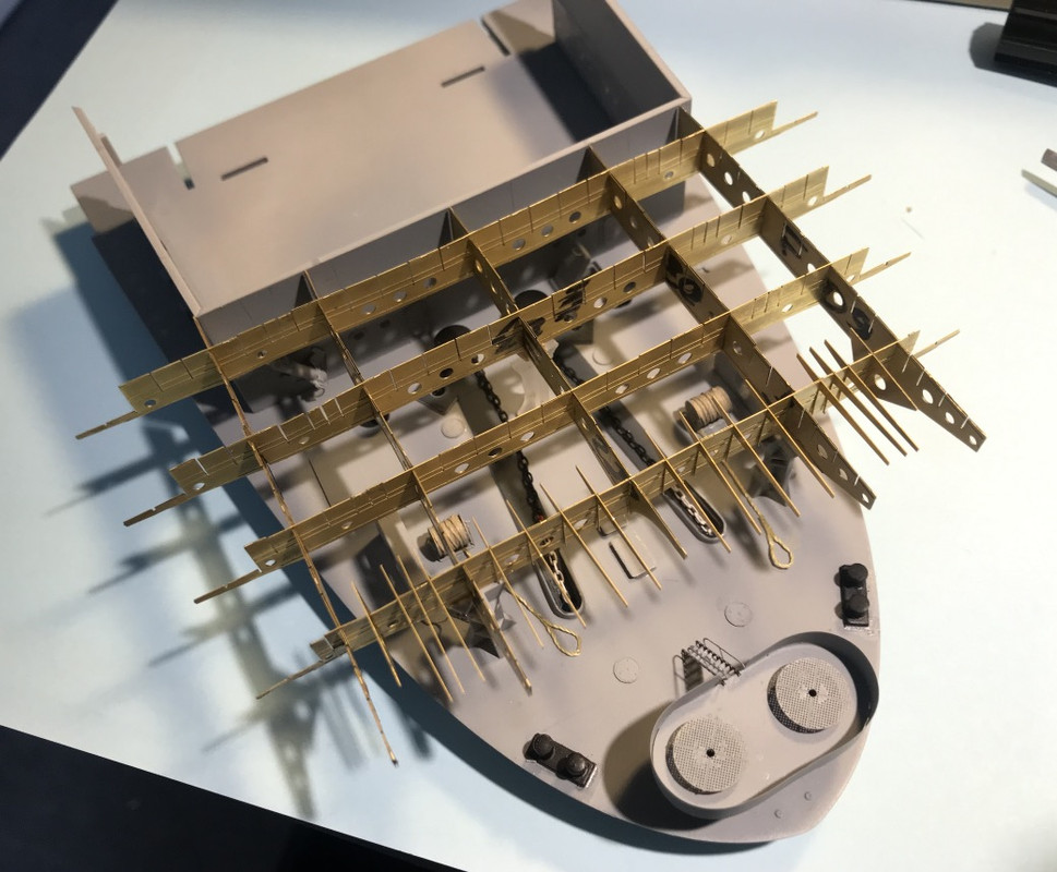
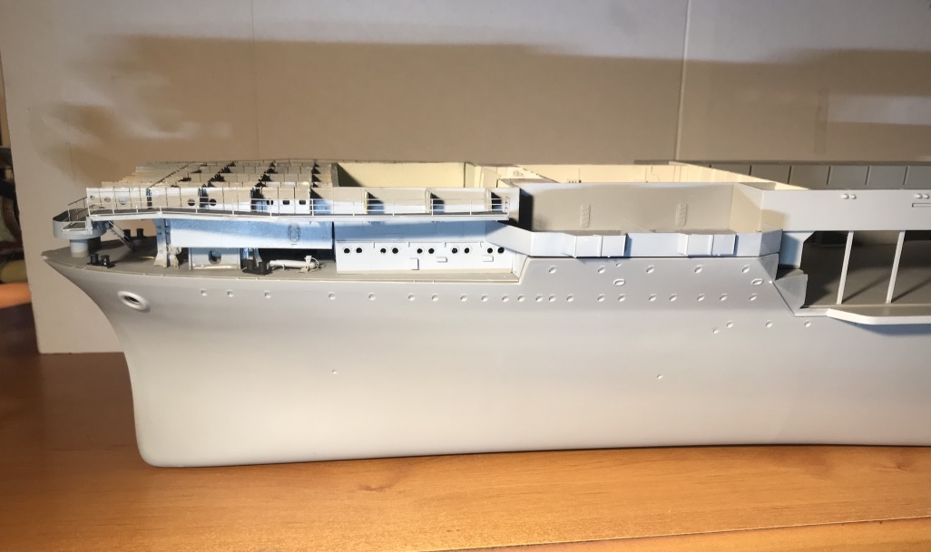
Forward walkways around the flight deck...
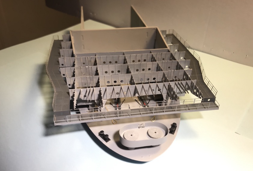
Spending several hours mounting the dozens of stiffeners on the flight deck support, it's very long.
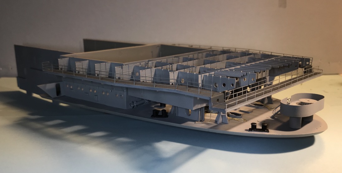
Then painting, some modifications of the front deck at the main supports.
With the flight deck for test:
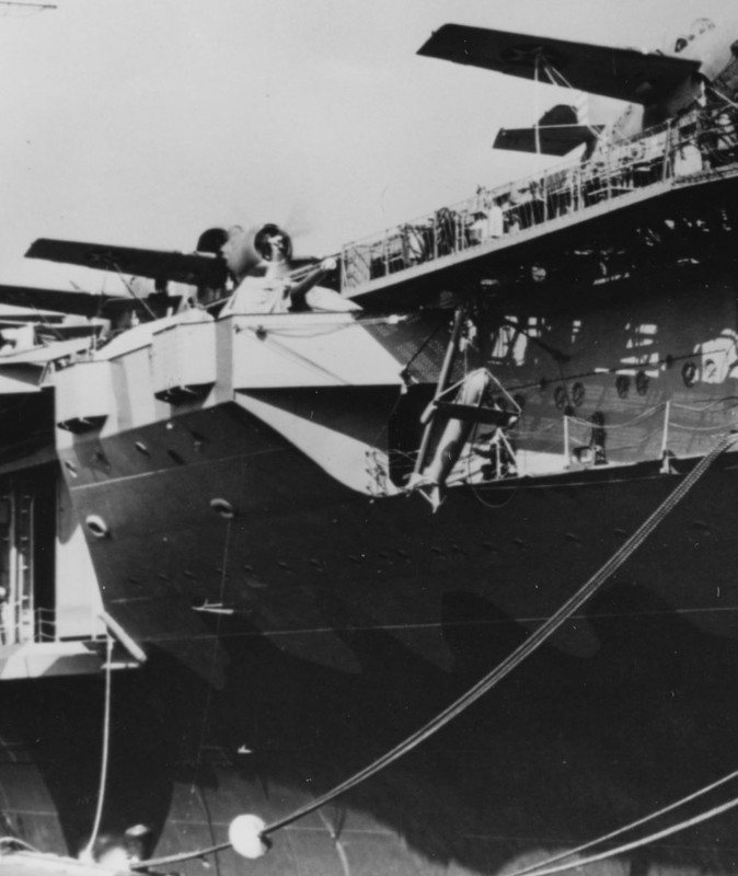
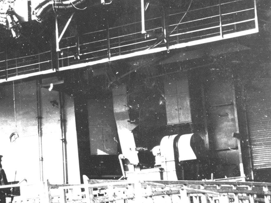
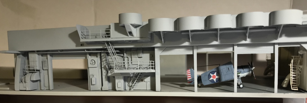
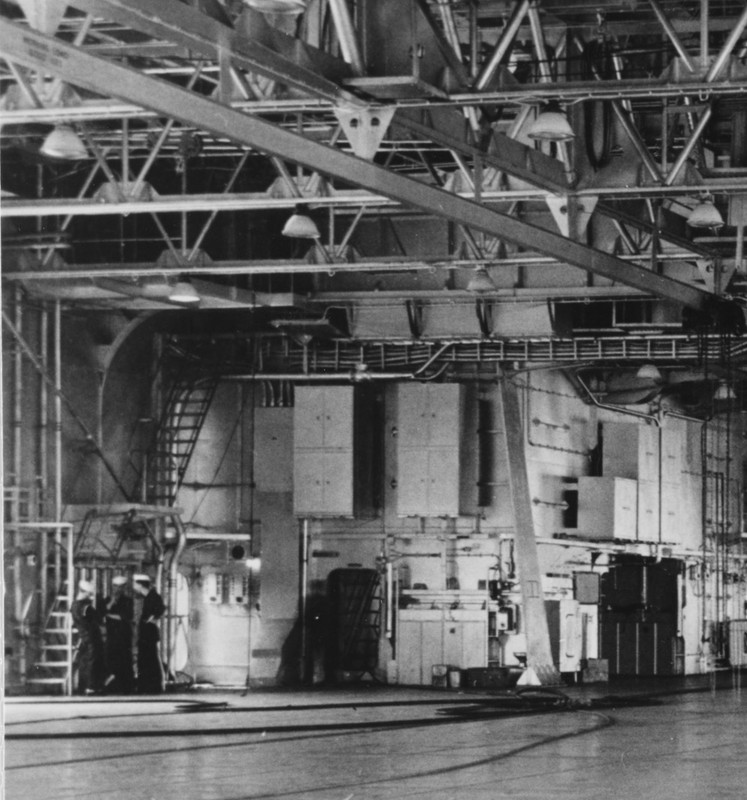
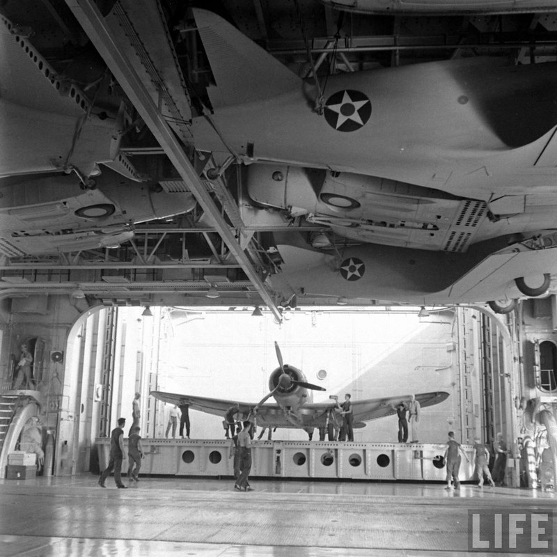
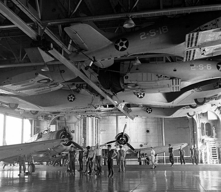
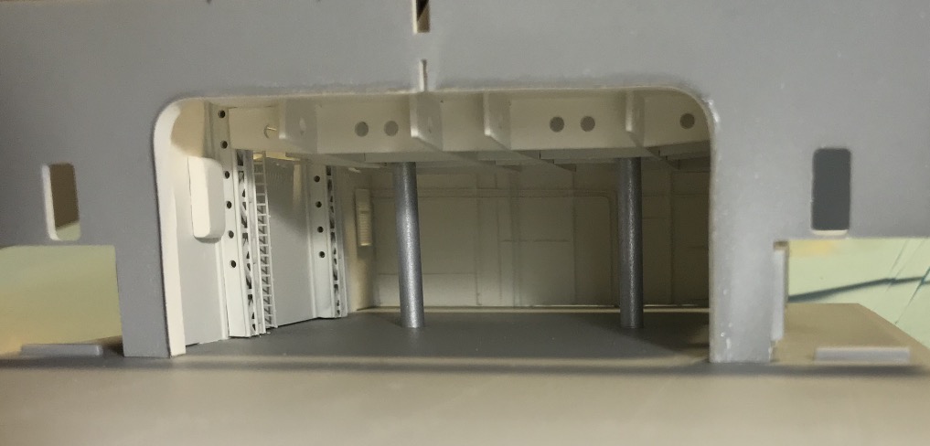
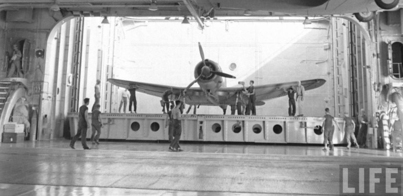
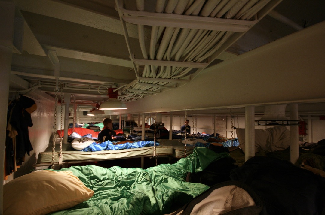
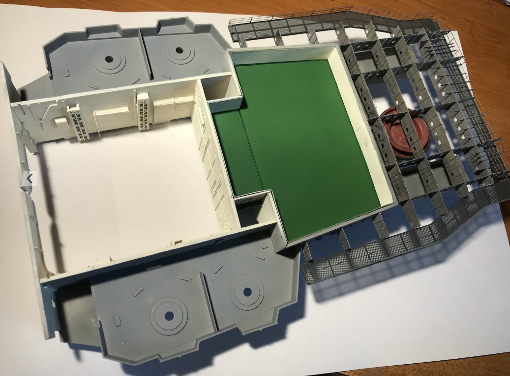
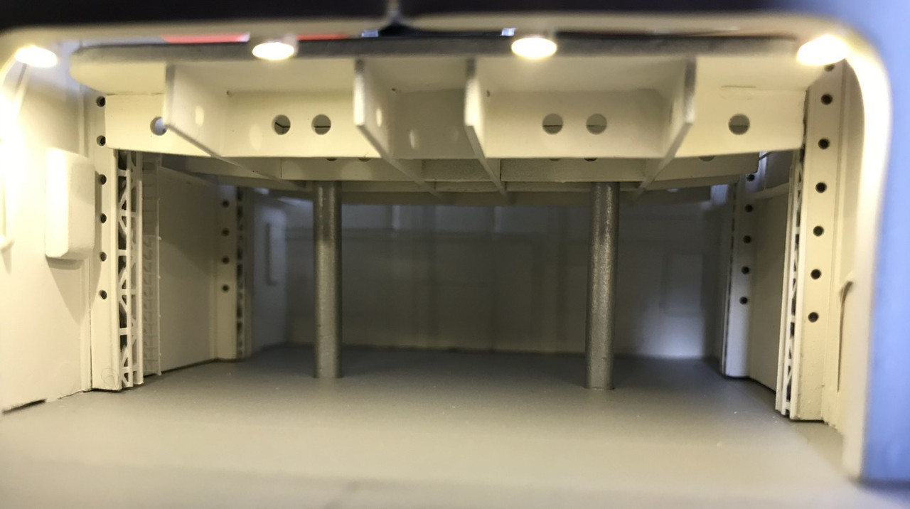
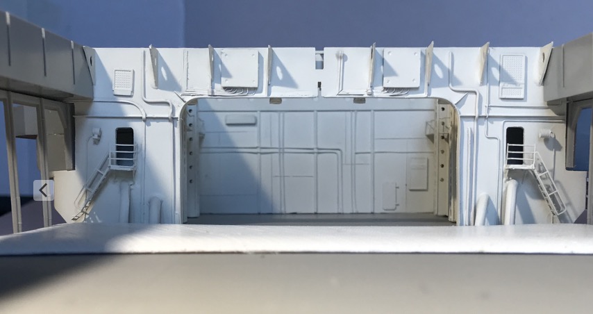
I've been looking for some photo doc for the front elevator room, it's thin, some pictures of the Yorktown class:
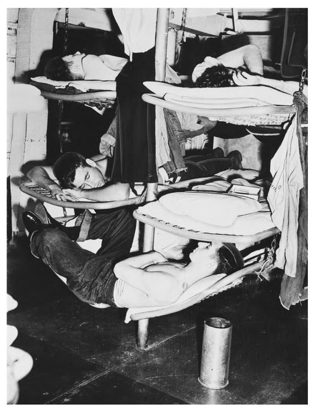
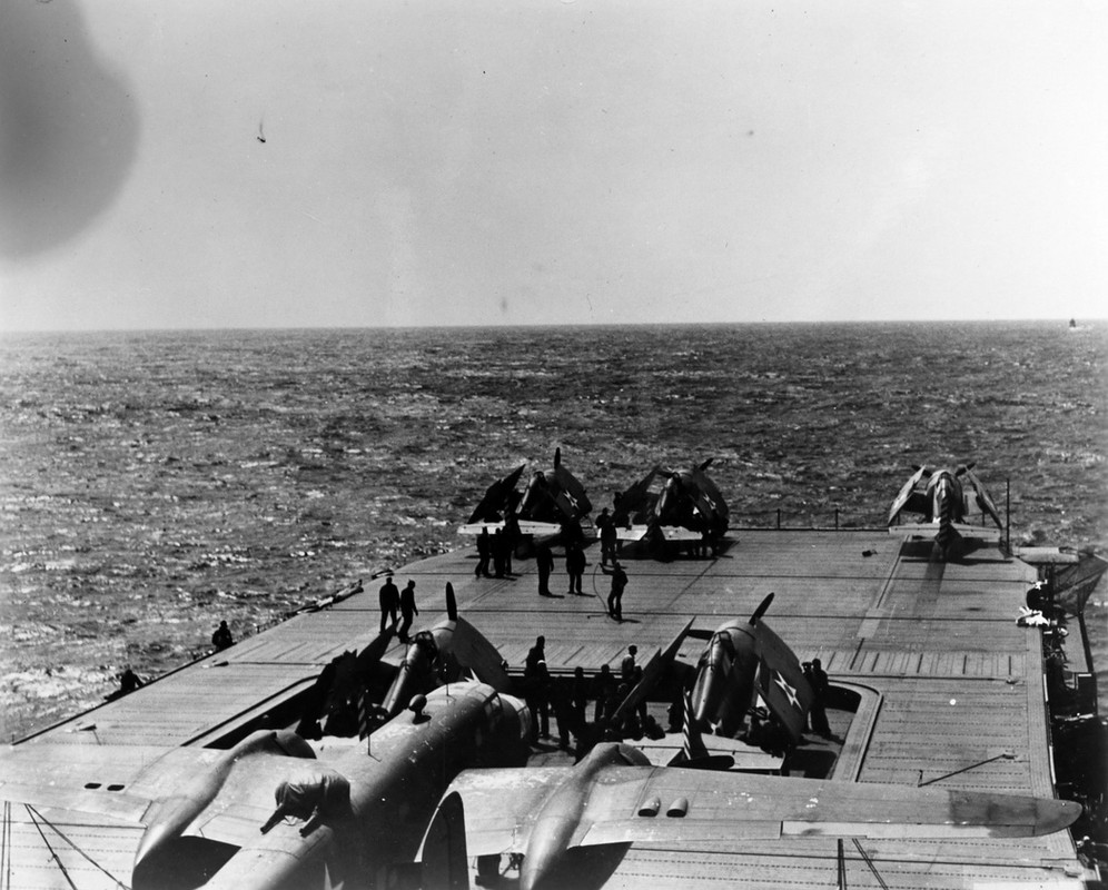
Here we see the new spare aircraft dismantled and glued to the ceiling, in peacetime it was a good solution to save time and space in the hangar, but in wartime it was sometimes catastrophic, the deck was not yet armored, a lot of bombs were coming through the flight deck and kissing these planes on the ceiling, these fires proved extremely difficult to put out.
We can also see that the work clothes are "diverse and varied" .
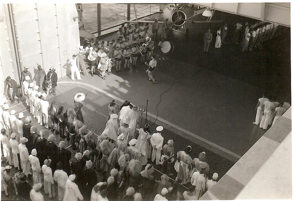
A typical crossing ceremony of the equator line. We can clearly see the shaft of the front elevator, as well as the location of the side catapults, the deck is thicker at this point and we can see the classic hangar deck (Main deck) move on any ship. The arching effect reinforces the structure, it's classic, it also allows the evacuation of sea water, sea package or fire extinguishing water.
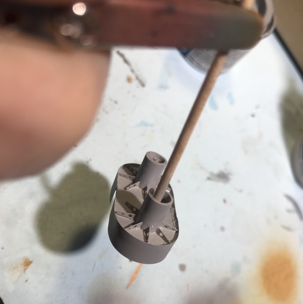
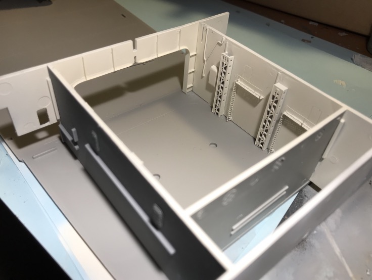
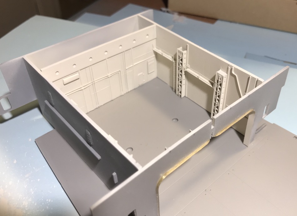
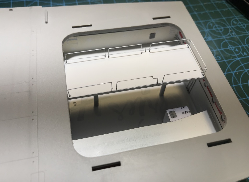
This room is not detailed so without PE or accessories provided, damage. Everything is done by scratch to make it look like something.
The elevator is composed of two hydraulic jacks, a little big on the model, I'll see if I replace them, the guiding of the apron is done by 2X2 side rails.
To simulate its rails I used what I had on hand in scratch.
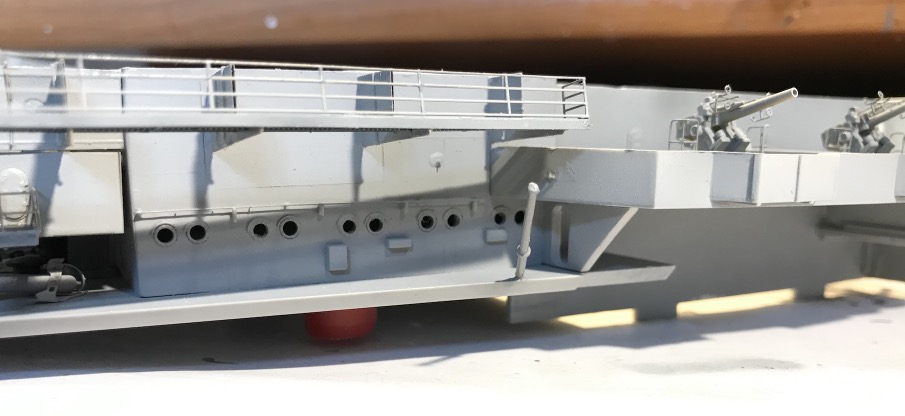
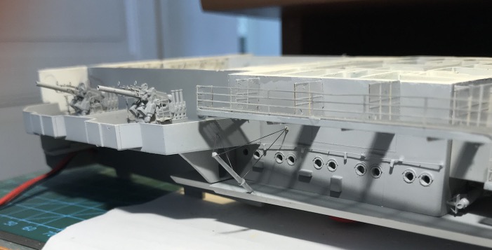
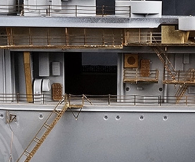
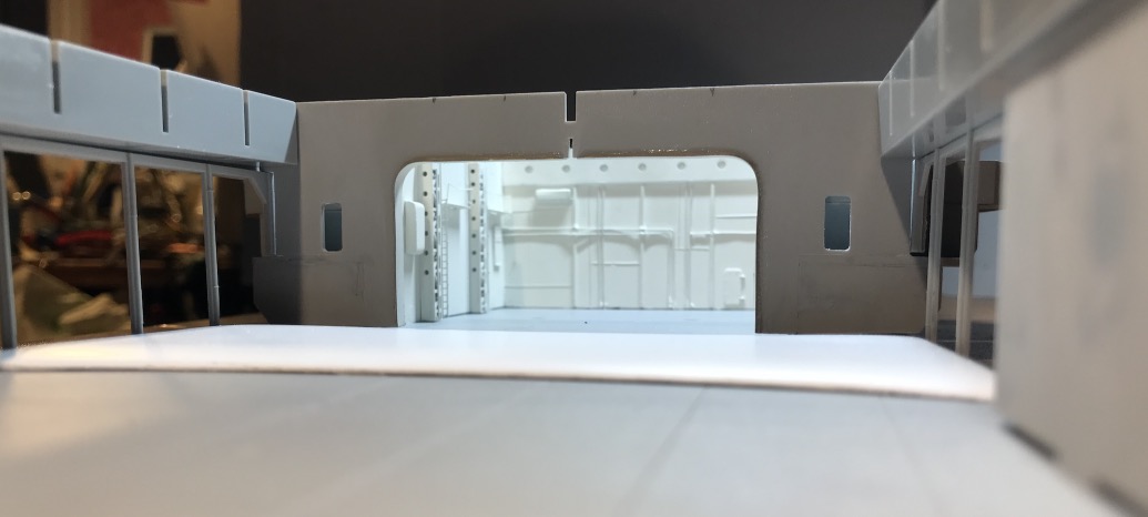
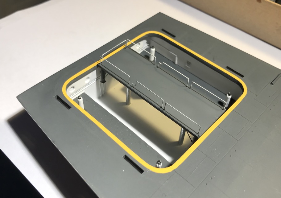
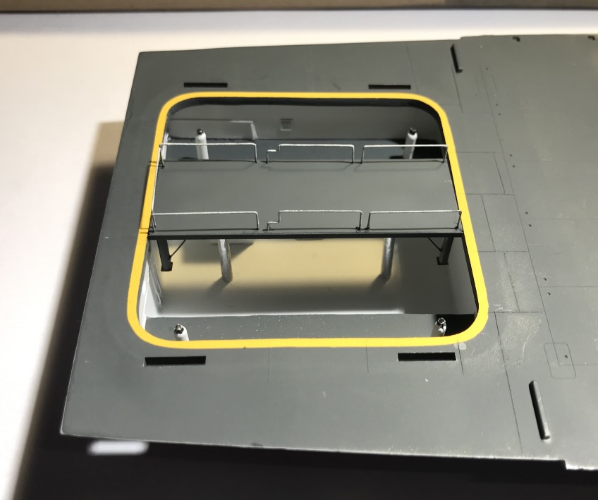
There are four watertight doors at the front AA batteries level, one seems to appear on the port side on the Yorktown plan, but 4 no, it opens in the top of the elevator shaft in the void on the model ... As they already exist and I glued the EP outside, I had to leave them. To make them credible as an emergency exit (in both directions) or for the lubrication of the elevator rails, I mounted footbridges with ladders. Of course, it didn't exist on the pictures, but well...
For the rest of the scratch, it's PE bundle, for the wall stiffeners, so recycling, iron wire, copper wire, and grappled elements in my stock on the right and left.
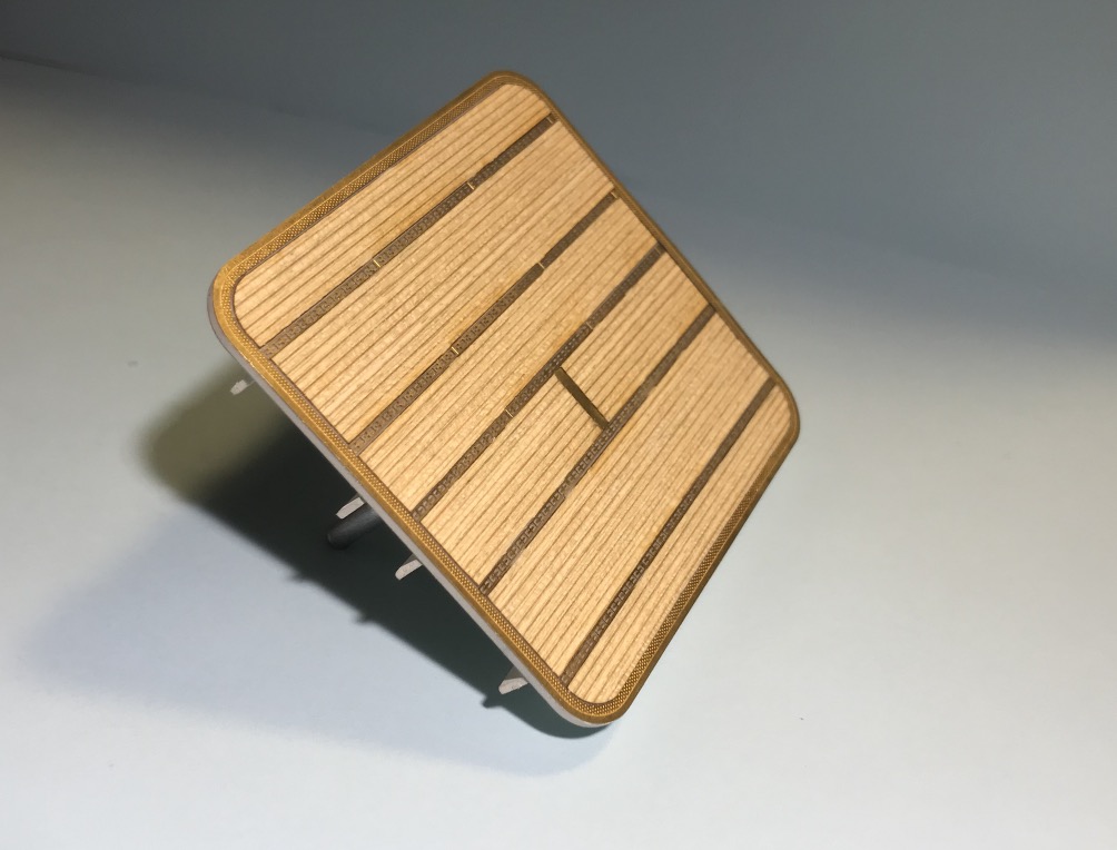
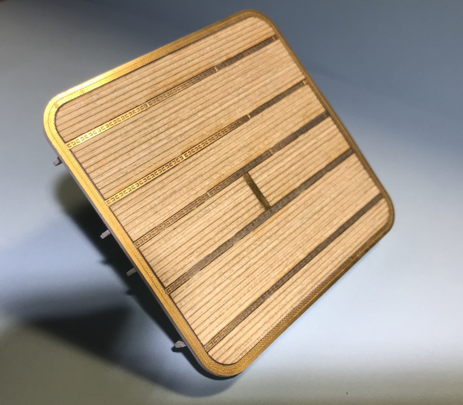
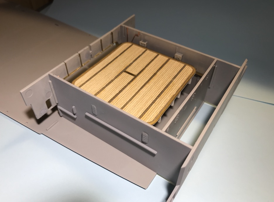
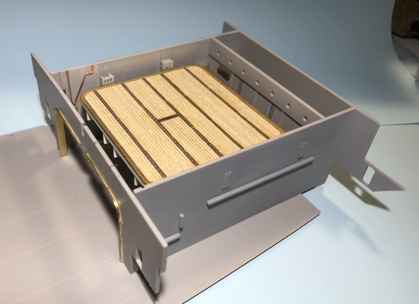
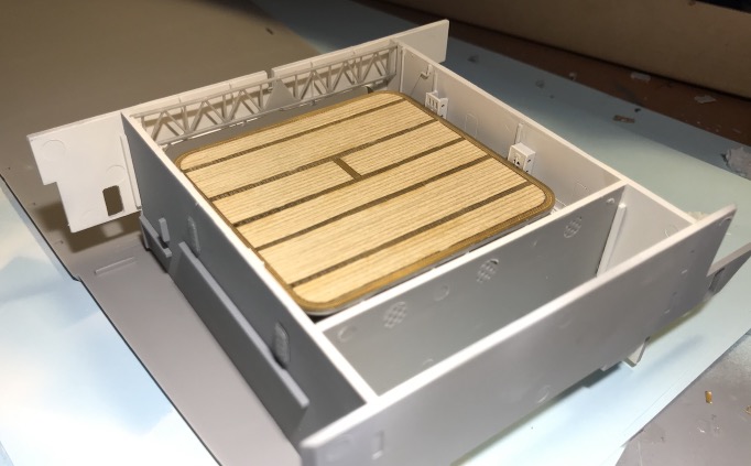
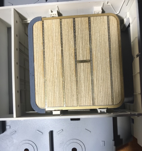
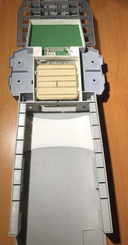
For the elevator, I glued the wooden floor, attention it is self-adhesive, it sticks well, even very well, but beware of the transparent film that protects it it is very fragile and tears easily, it's a bit of a mess. for a small surface it's ok, but for the big ones I'll have fun. The positioning has to be perfect because of the PE, especially if we couldn't glue the wooden bridge in one piece.
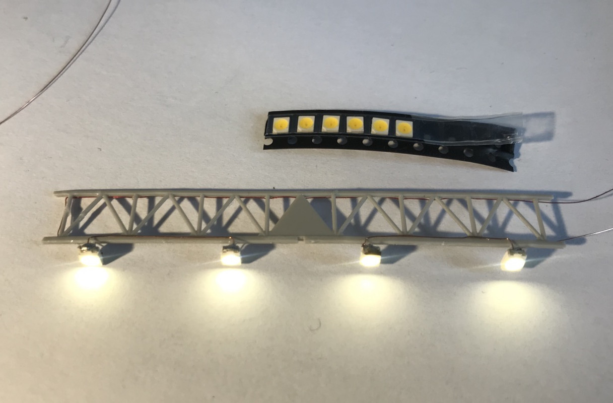
I've ordered micro-leds for the hangar lights. I'm going to solder the wires myself, as I'm going to put very thin copper wire so that he can't see very much, it will look like wiring considering the size.
Dimensions:2.8mm x 3.5mm x 1.9mm Operating voltage: 3 - 3.4 Volts Intensity: 30mA
The painting was done with Revell N°5, a white that is very slightly broken and matt, I would see if I slightly yellowed the tops of the walls in gradation, the white paint tends to yellow faster in the tops of the compartments.
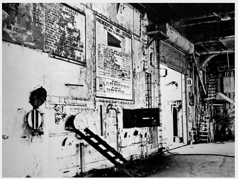
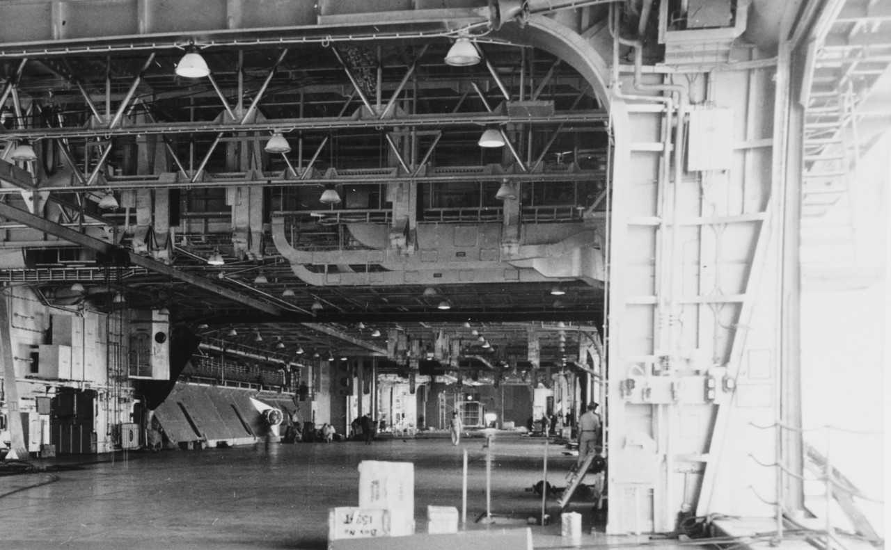
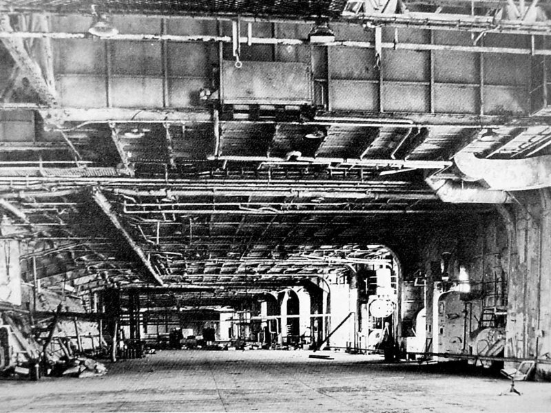
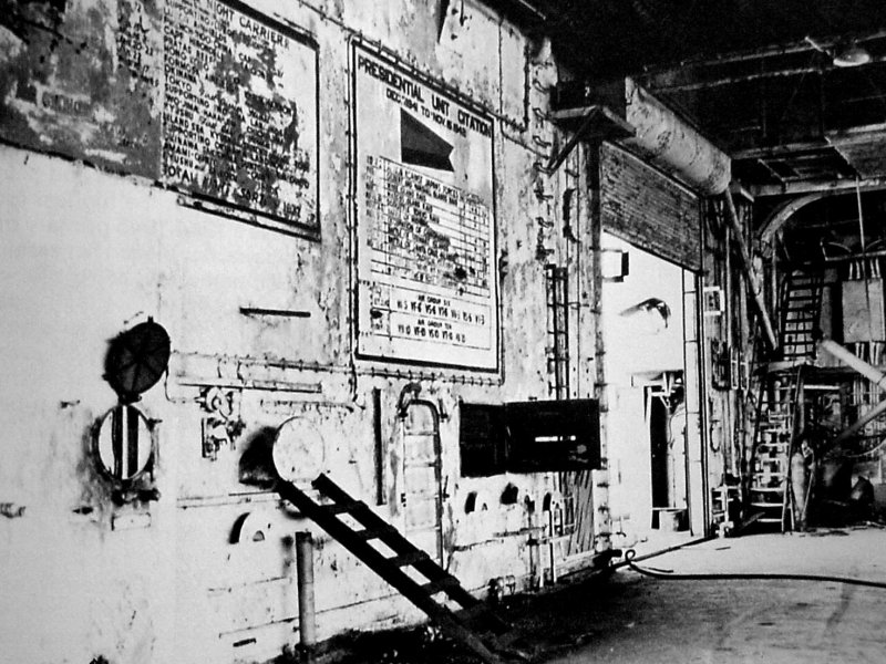
These are photos of the Enterprise CV-6 Big-E ( Same class) hangar during its demolition:
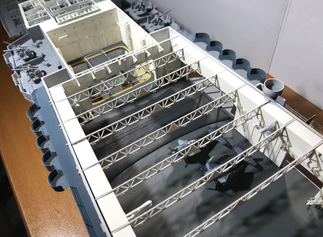
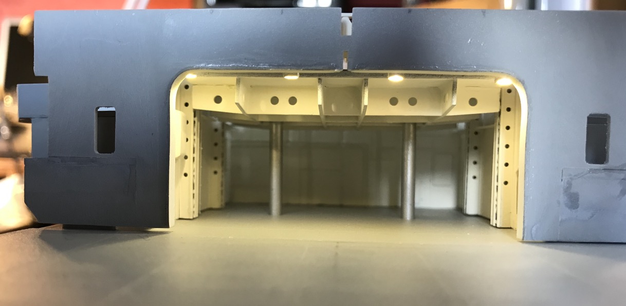
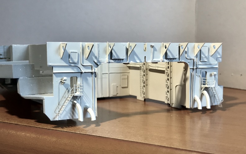
I continued the assembly around the lift of the walls and the AA platforms from the front. Of course I mounted everything on the hull to make adjustments.
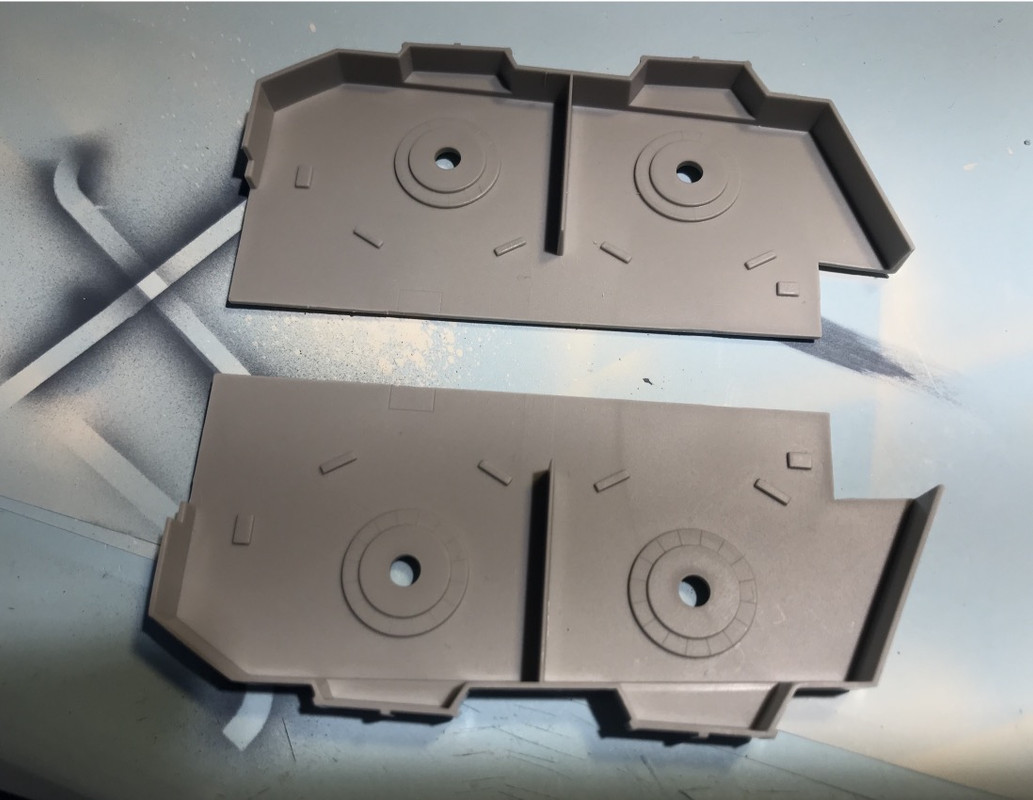
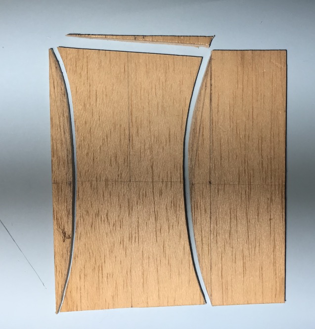
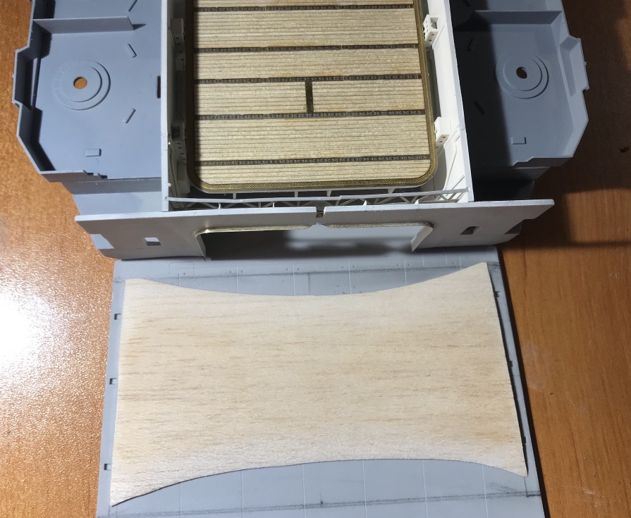
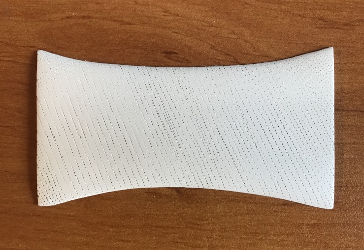
I also made the curved floor of the side catapults out of balsa wood. I loaded the balsa once formed to the antique hard bottom to make it less porous to paint. I will prepare it, once dry, with a spray can.
On the AA platforms I also pierced the passage of the stairs leading to the hangar. The place is marked but not cut out on the model.
I think I will make the flight deck removable, fixed with small invisible BTR screws hidden. Because it would be a shame not to see the inside of the hangar.
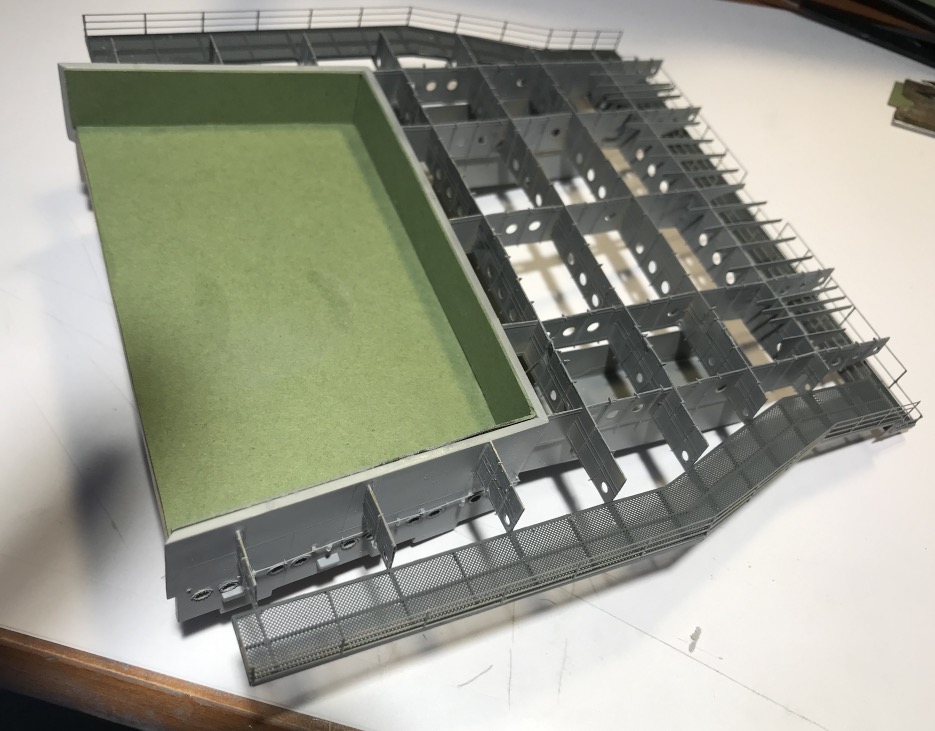
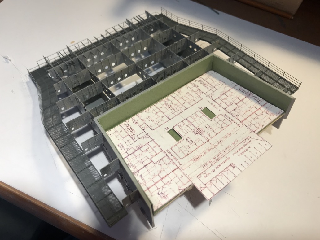
So I'll probably fit out the forward block, the top floor which contains cabins, showers and toilets.
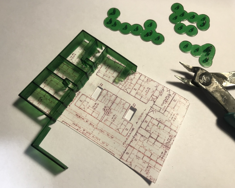
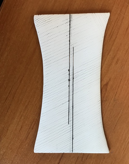
I will try to make this floor out of very stiff but thin paper. It will be simplified of course.
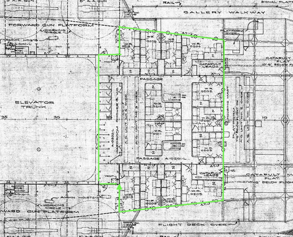
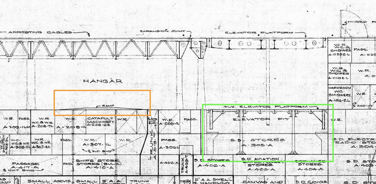
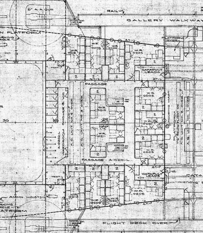
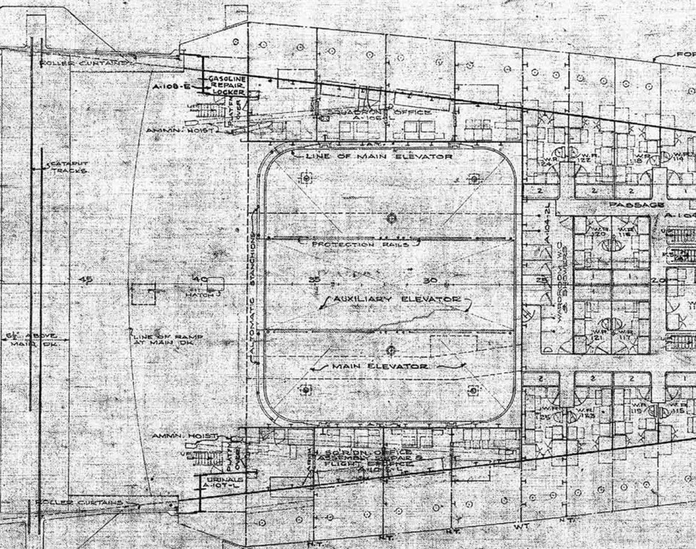
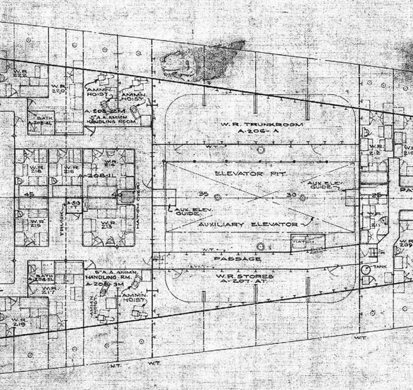
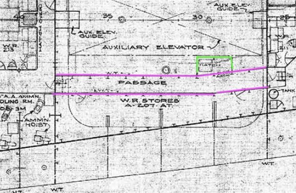
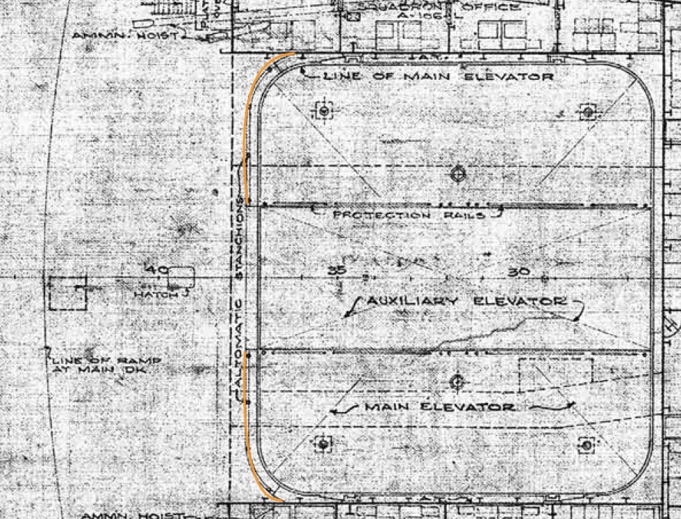
This is the floor plan for this floor:
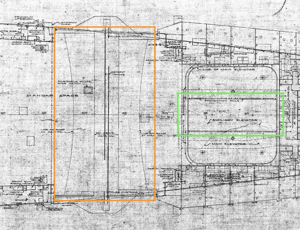
In orange the curved floor of the 2 catapults which is flat in its width, the deck of the hangar being curved (the gouge) him, (not on the model), one sees the curved development of the floor of the catapults at the front and at the back of the room.
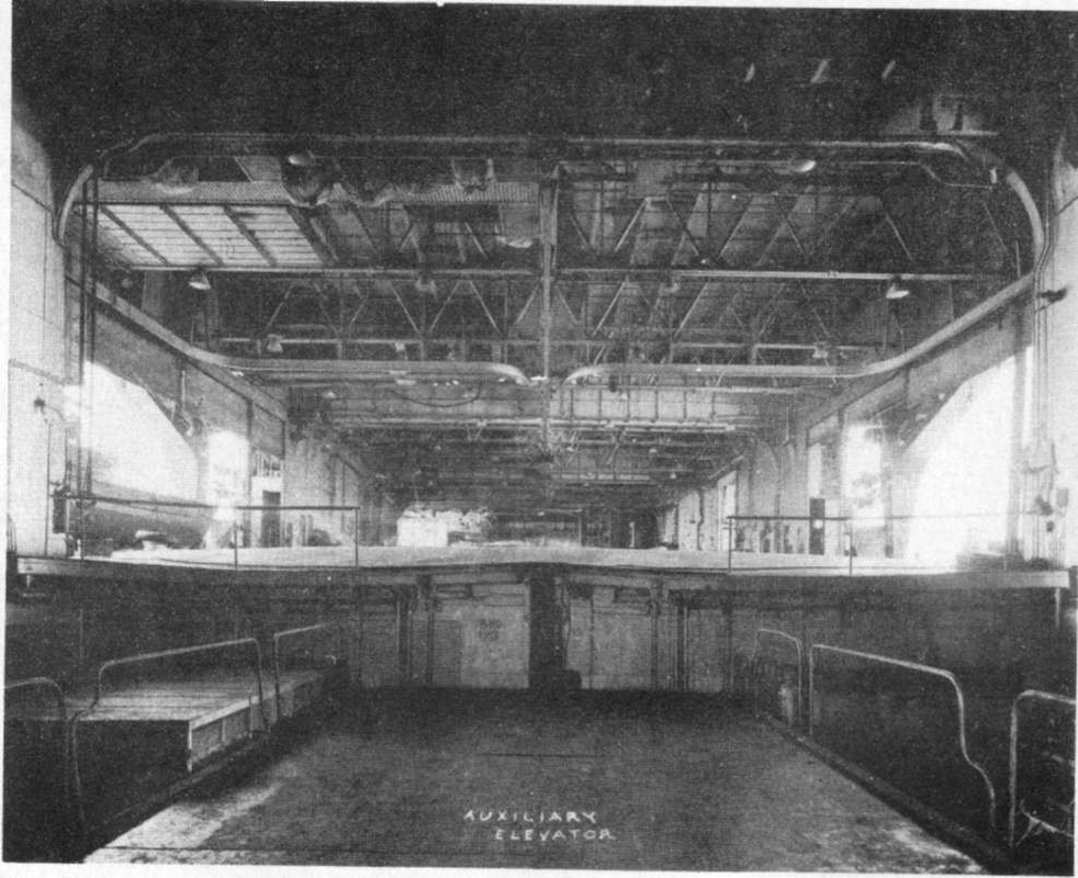
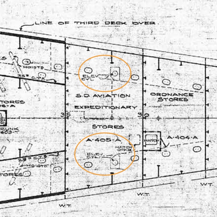
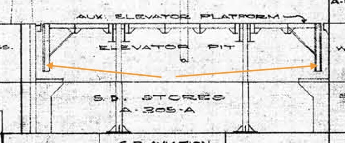
In green, we can see the smaller auxiliary elevator, it allows to park maybe two planes under the main elevator when this one is in high position, at its sea station.
The auxiliary has a rectangular shape and fits between the two jacks of the main one. When the main elevator is used, the aux descends from a deck to make room for the main, on the plan you can see its own jacks and its feet allowing them to land two decks lower.
You can see the overhang on the right of the picture, and the shape of the floor catapults. It is covered with Pirelli anti-skid material. A type of anti-skid found on many modern catwalks or machine PCs.
AA platforms forward.
The manufacture of balsa wood catapult flooring.
USS HORNET (CV-8)
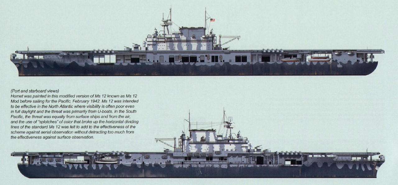
Measure 12 (mod) Camouflage, as depicted in the Trumpeter 1/200 kit and the Tamiya 1/700 kit
Ship:
Darkest colour on the hull-5-N Navy Blue (US 08);
Lightest colour on the hull, and darkest colour on the superstructure-5-O Ocean Gray (US 06);
Lightest colour on the superstructure-5-H Haze Gray;
External steel decks & other horizontal surfaces-20-B Deck Blue (US 10);
Hangar deck bulkheads & overheads-5-U White (C 03);
Boot-topping-Black (C 02);
Underwater hull-Norfolk 65-A Antifouling Red (US 14).
Aircrafts:
Carrier aircraft were in Non-specular Blue-Gray (ACUS 05) over Non-specular Light Gray (ACUS 06). F4F Wildcat cockpit interior colour was Bronze Green (ACUS 30 ); SBD Dauntless cockpit interior colour was Interior Green (ACUS 09). TBD Devastator cockpit interior colour was Interior Green (ACUS 09),
B-25s were in Olive Drab 41 (ACUS 15) over Neutral Gray 43 (ACUS 13); B-25 interior colour was Interior Green (ACUS 09).
Later I found a rare photo of the auxiliary elevator:
Entreprise CV-6:
Interessant video of a Wildcat (Kermit).
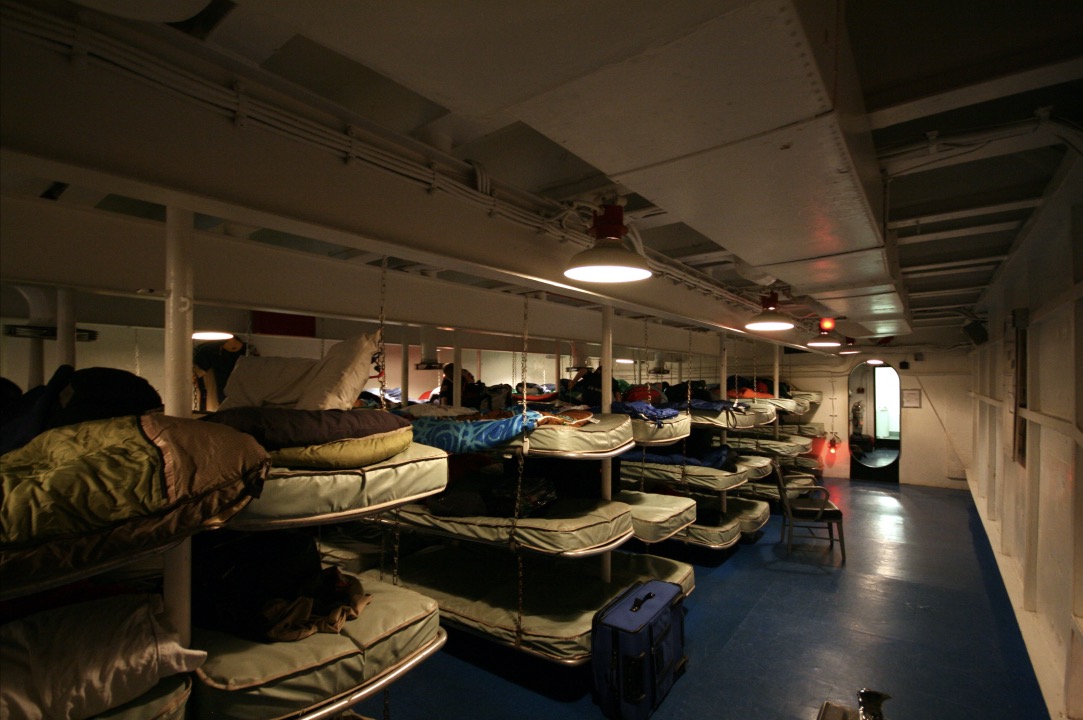
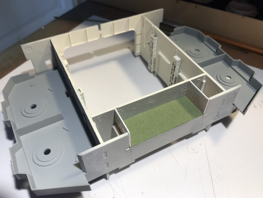
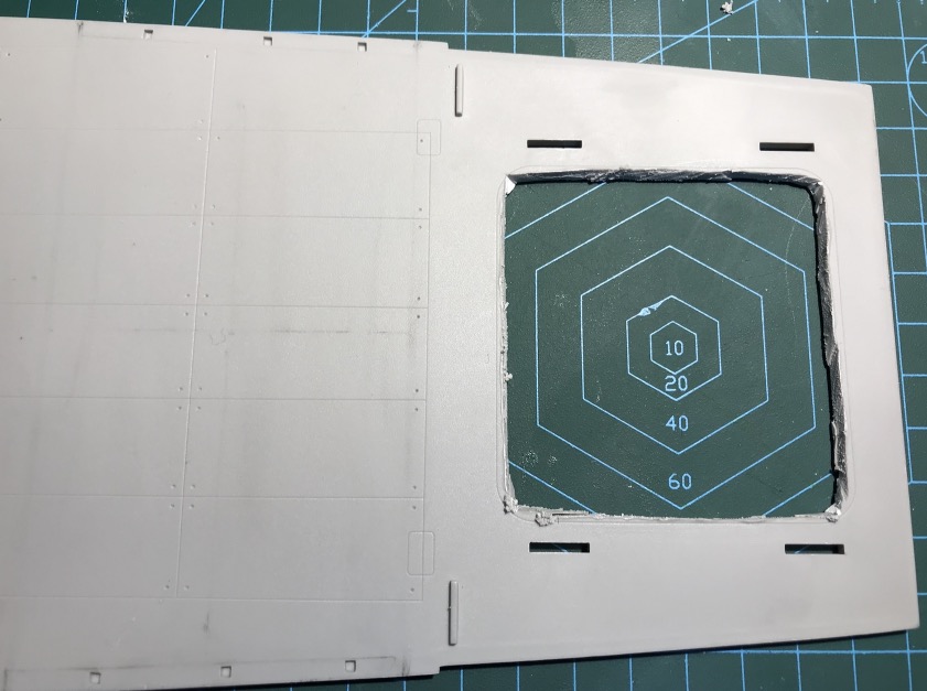
The question arises as to the colour of the floors in the layouts, stations or double cabins, as the partitions are probably white like the hangar.
The floor can be dark blue like here on the Yorktown CV-10, which has become a museum.
The typical large ashtray from a munition...
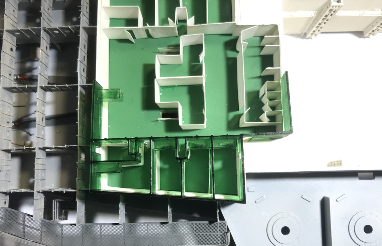
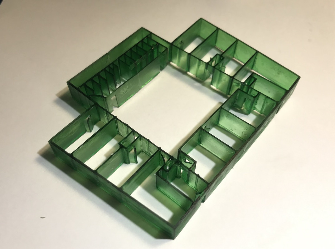
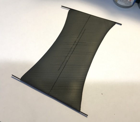
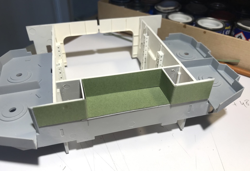
Since my card is green, I'm going to go with green... Revell SM364 English Green satin.
It's coming along, I just need to get a little more control over the paint job on the cardboard.
I had to mask to make the baseboards, tape, paint and cardboard don't mix. I'll do some white overlays, for the second sector it'll be better. Besides, everything was already mounted, so it's not so easy to modify...
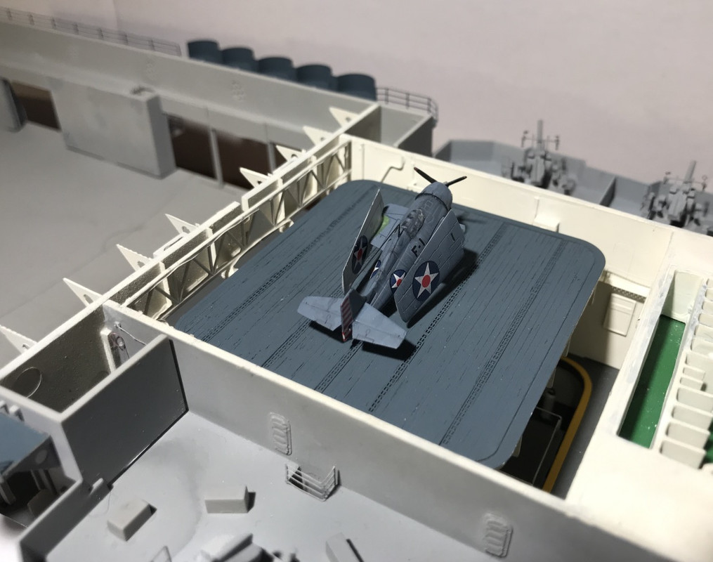
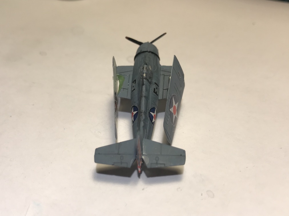
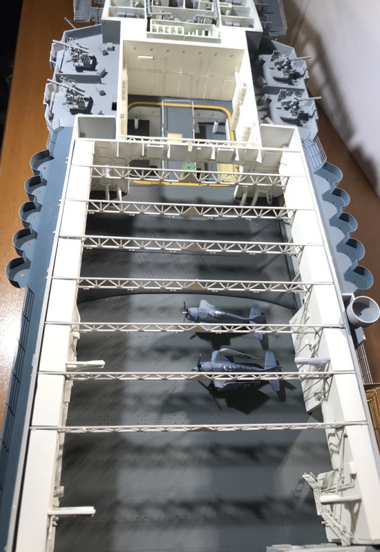
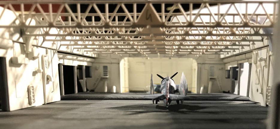
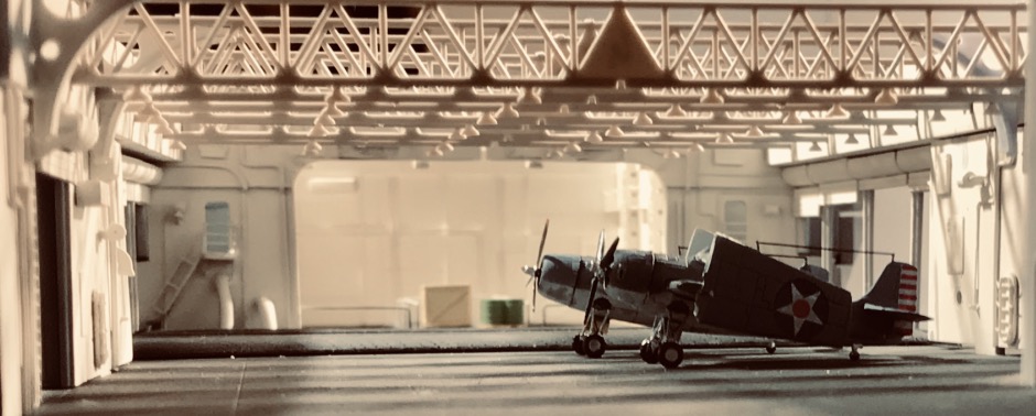
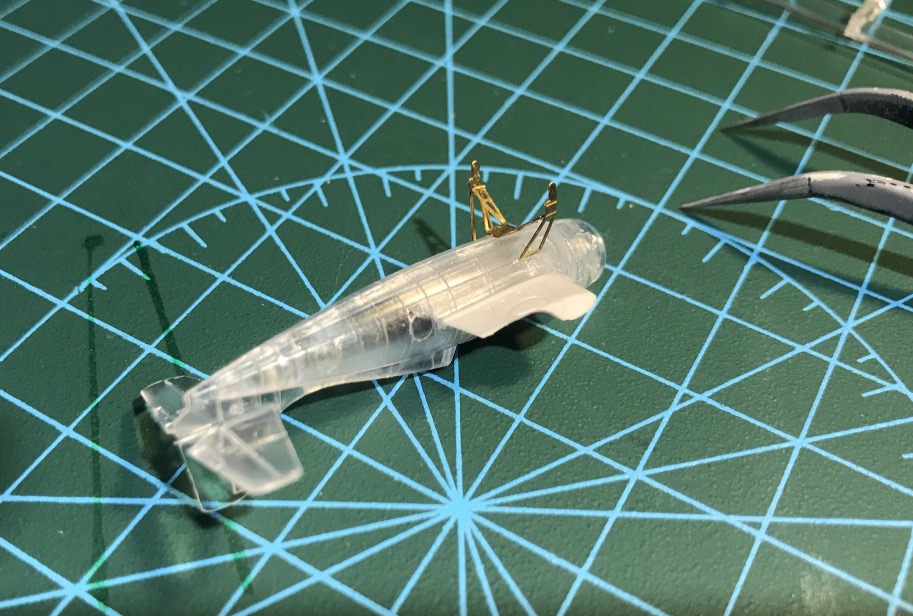
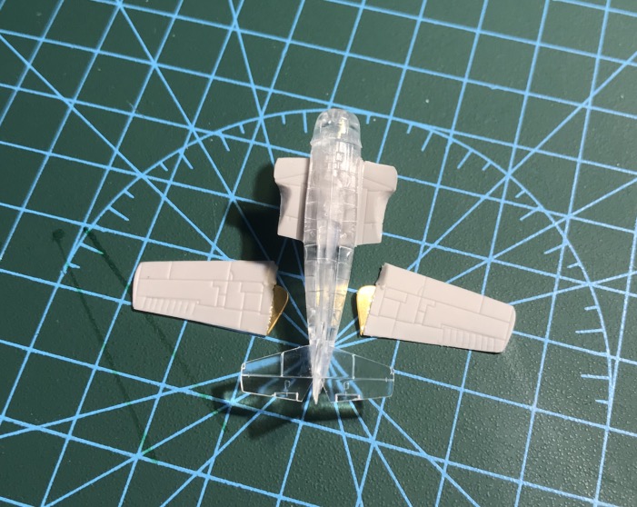
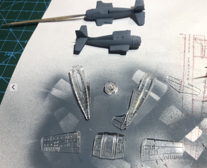
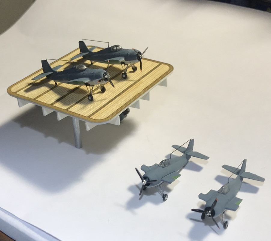
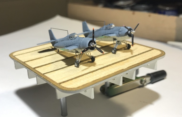
Assembly of the first Wildcat F4F-4 with the wings folded.
Simulation of anti-skid on the floor side catapults. It's going to be painted anthracite.
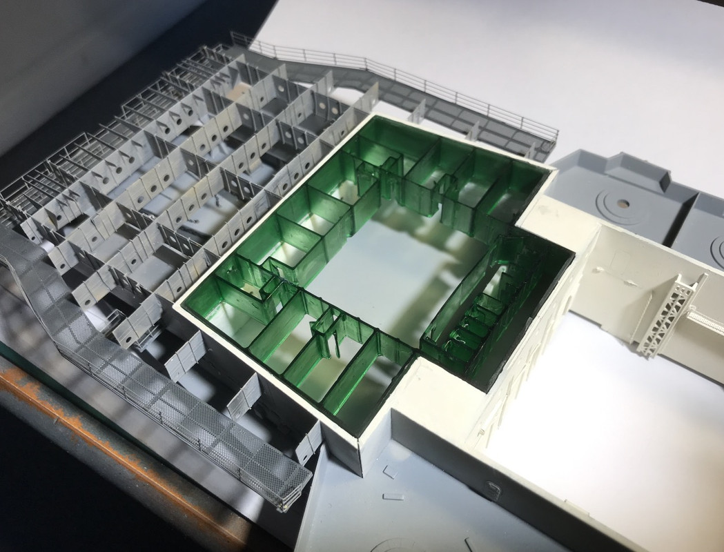
Accommodation is progressing well.
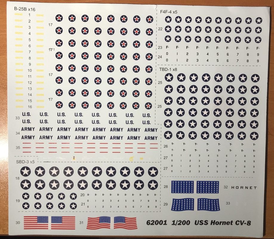
I don't think that the black markings on F4F-4, SBD-3, TBD-1, don't match the time of the raid...
I would have to add the red circle as on the B25 (Mask?).
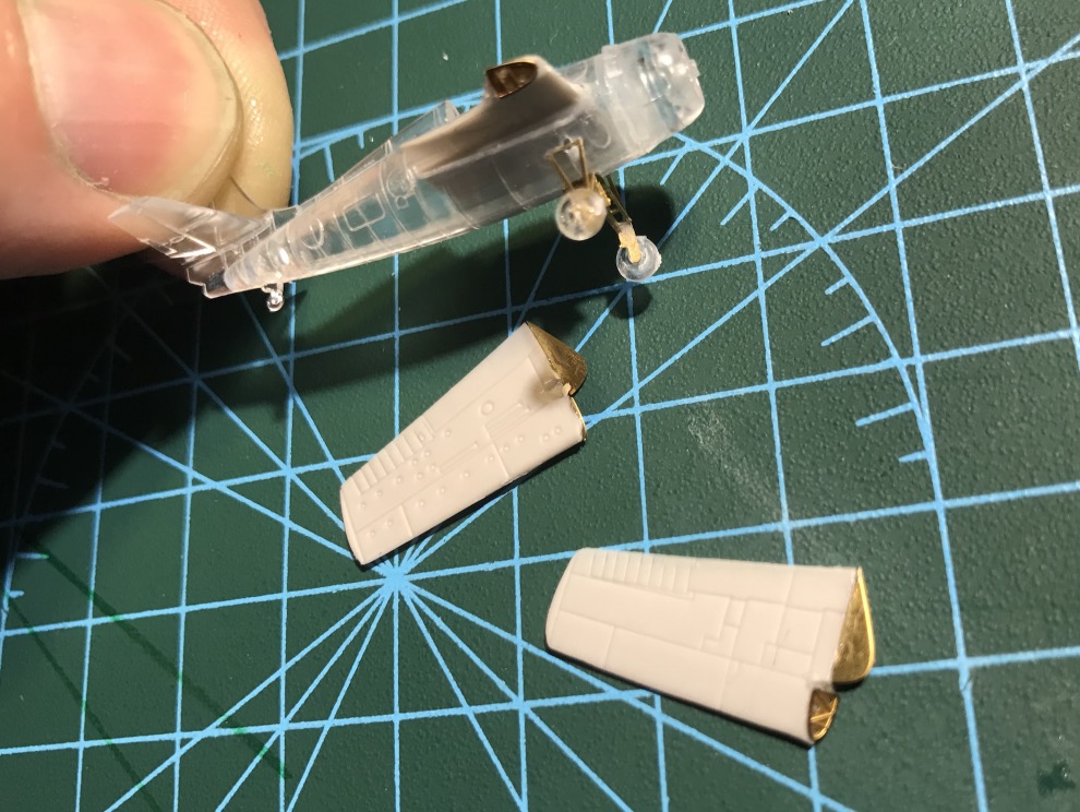
I mounted four Wildcat's and painted.
I still have a few more landing gear hatches to put up.
I haven't glued the wings yet, as I'll have to get the right vintage decals before.
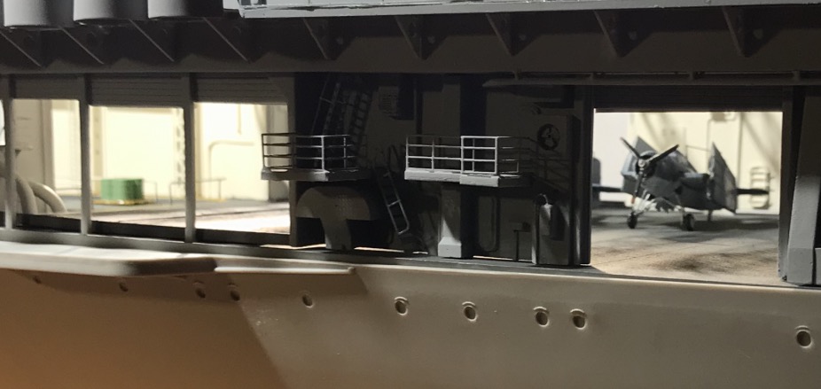
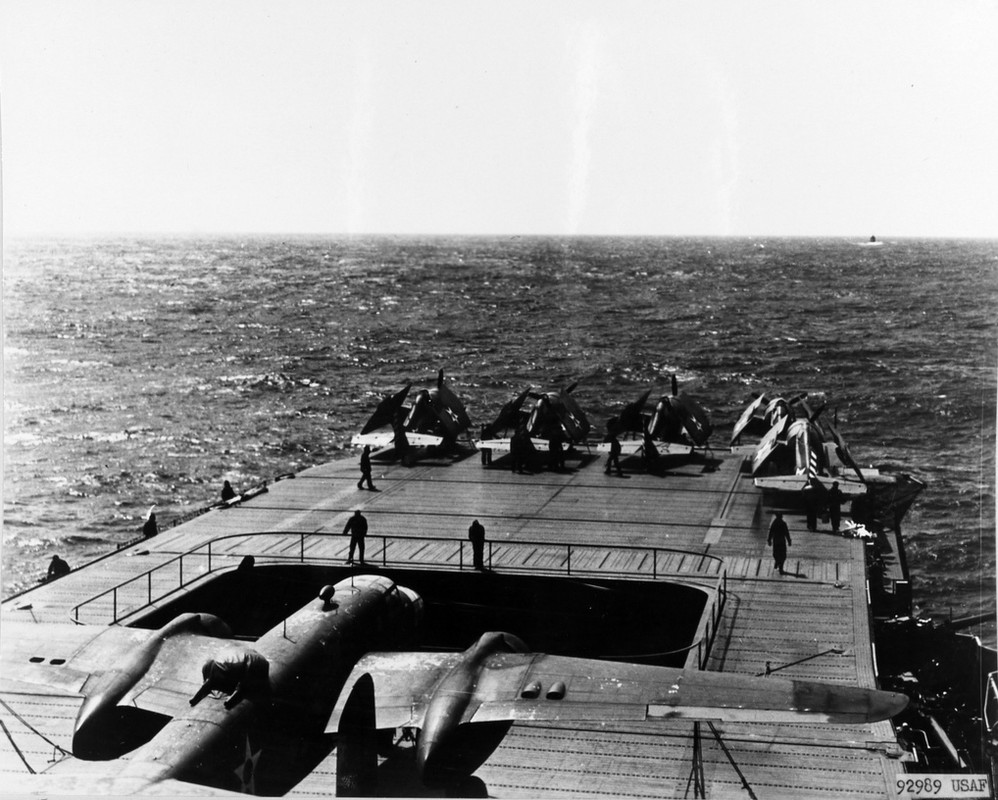
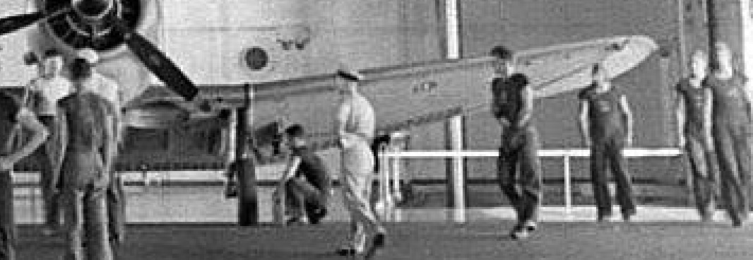
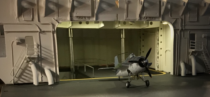
There will be 2 F4Fs on the front elevator. As on this picture taken before the raid, the 2 aircraft are being mounted on the flight deck to be parked at the front:
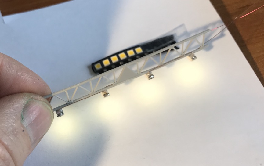
Received my CMS leds, they are perfect in terms of light color, rather warm.
I supply 12 volts because I will put up to 5 in series with a suitable resistor.
Here for 4, at put 1k ohms. I set to have a weaker light well yellow thus little Milli-amperes. I'd have a total of about a hundred to set up for the hangar.
They go in place of the original lamps, I could have put a lot less, but visually it didn't work.
The 12 v power supply will be done by a transformer, the 12 volts wire for the general power supply will go through one of the hollow feet that will fix the hull to the support. No visible wires.
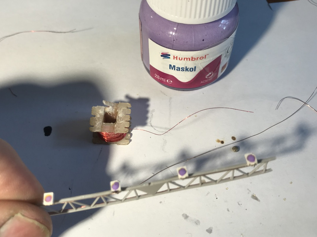
Wiring.
Then painting, little Mascol to protect the leds.
Only 19 more ramps like this to go up...
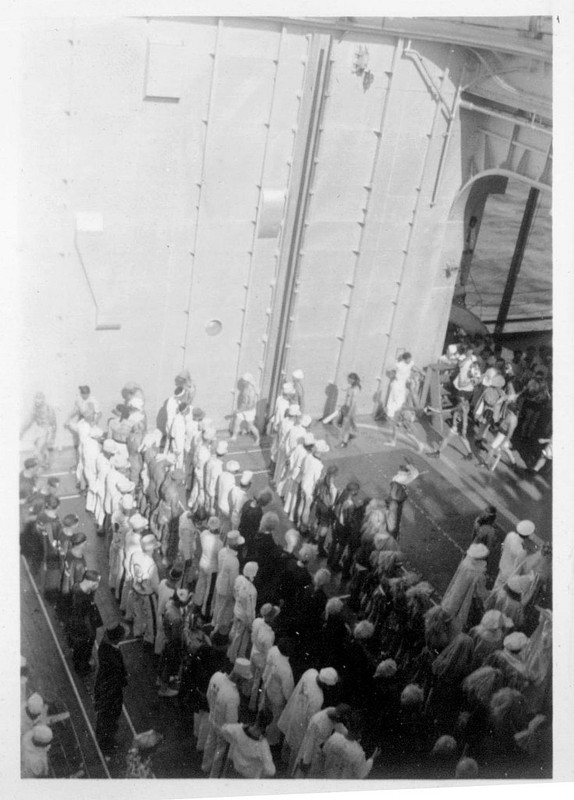
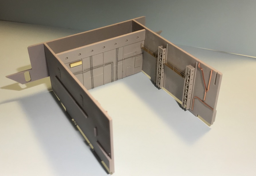
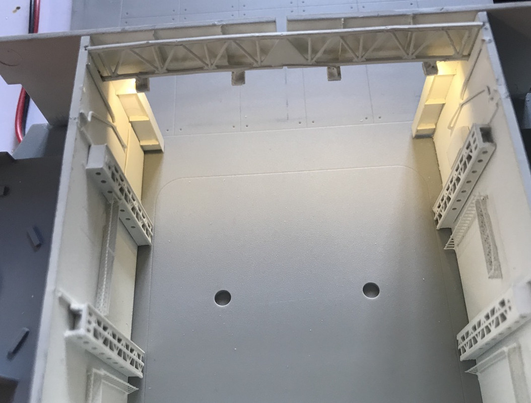
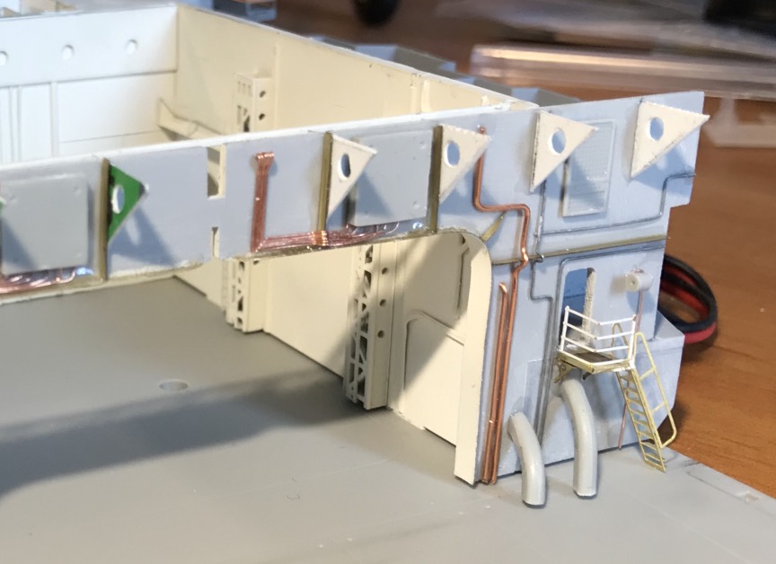
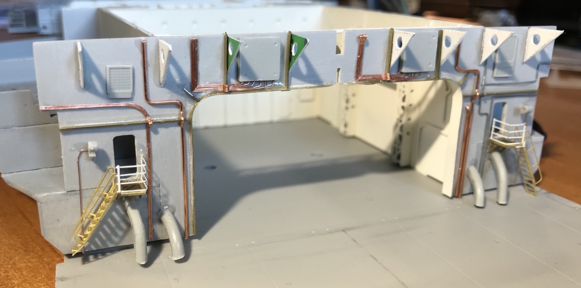
We had to "furnish" this partition, which was quite empty... It took a few hours, only scratch or salvage, nothing is planned in this model to furnish, by the stairs, badly turned by the way.
Sanding, putty, sanding, putty, sanding...
The 4 large elbowed pipes that can be seen are the elevators to move AA ammunition from the ammunition bunkers to the AA batteries in the front.
It's much better when it's painted.
If you want to spot defects on your model during assembly, take macro pictures, I can tell you that they are much easier to spot than with the naked eye, and you can rectify them. It's a bit like recording yourself singing or playing an instrument, the verdict is terrible...
I drilled into the hangar deck to make the previously planned modification to the auxiliary elevator addition...
I have two decks to create under the hangar floor at the front elevator level, a little extra work.
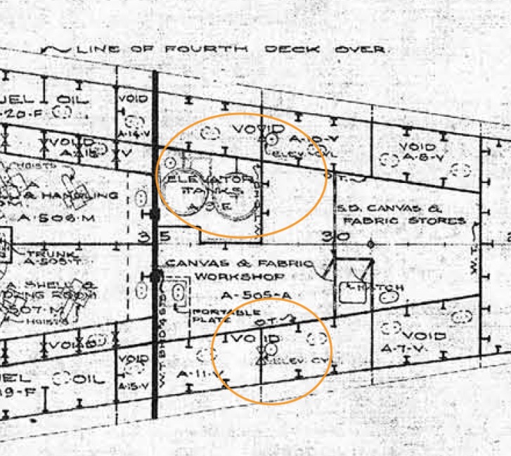
Main deck (Hangar)
Second deck.
3rd deck.
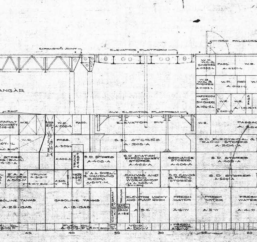
Transversal view:
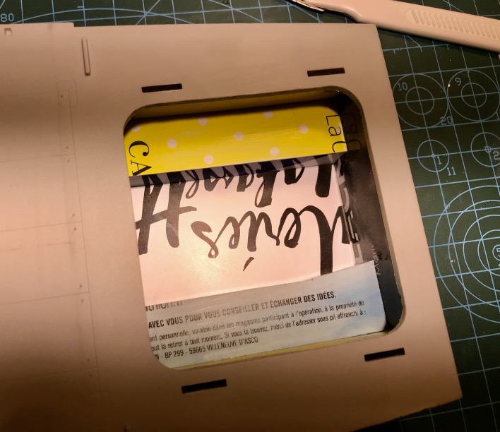
Cutting with the Dremel circular saw, do not make any mistake especially.
Adjusting, if the elevator goes in it's fine.
I can do the big scratch.
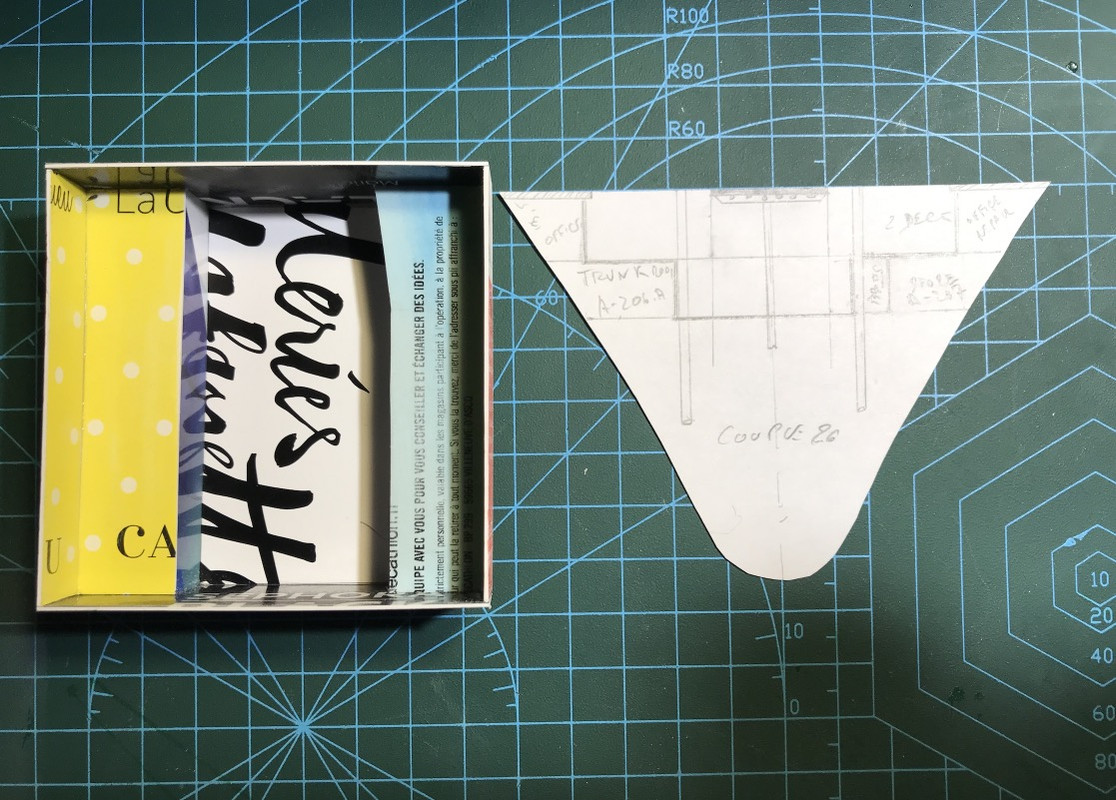
I put a picture of frame 26 with the plan of the decks, it is used as a master couple to define the plates to be cut. The measurements are right model versus plan of the original Yorktown except that the lift is a bit longer, so it must be taken into account, otherwise the hull shape seems correct at first look.
I carved it from my wife's loyalty cards. She'll be the ship's godmother for all I care! I leave it up to you to find the names of the various shops that have sponsored me!
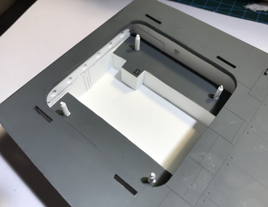
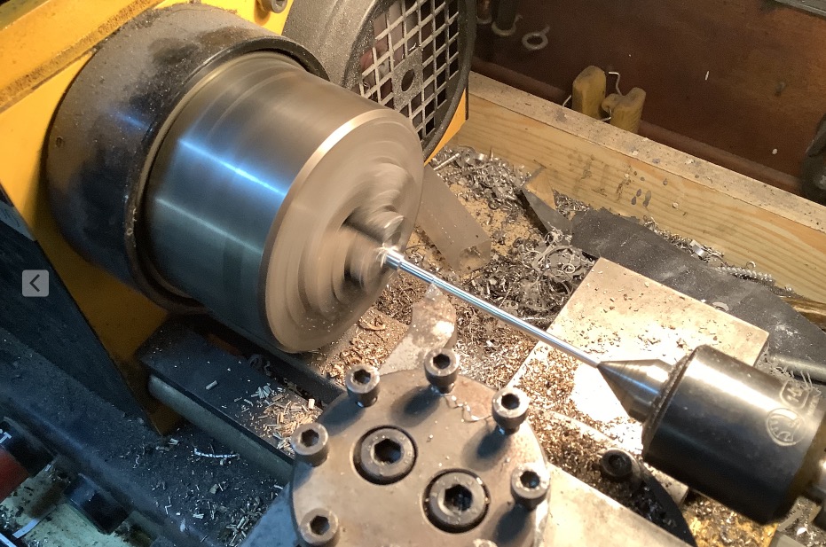
That's it, it's almost over, my big improvement with only scratch. The two hydraulic jacks of the main elevator still need to be made, longer and thinner, on the lathe and made of aluminium as shiny as chrome.
Some small flaws to erase here and there, but nothing serious, nothing is really glued yet.
The elevator's safety rails are made of very thin 0.3 mm piano strings that I just received. Those in the middle on the right and on the left have a particular shape each and different, maybe to let the beams of the main elevator structure pass through when it is in the low position.
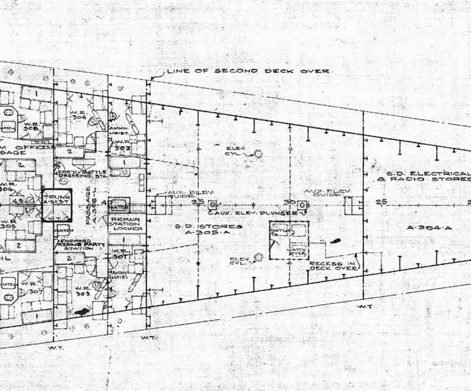
There is an escape hatch on the starboard side, probably an emergency exit for the lower decks. Next to the escape route, there is a passageway that crosses deck 3 of the elevator from forward to aft. As a result, the td 207 store is smaller than the 206 at bd.
Manufacture of the new, longer aluminium jacks, drilling of deck 3, these jacks go almost all the way to the bottom of the ship... The hydraulic power plant is on the first platform. I'll stop at deck 3...
And underneath the first platform with the hydraulic power unit of the lift or front lifts to port.
......I'm really coming to the end of my modification for the auxiliary elevator, it will be faster for the next two, the procedure to follow is now known.
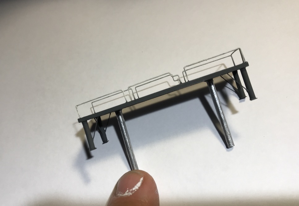
I've finished completely mounting the Aux lift, I had its 4 feet to add. You can see them on the plan.
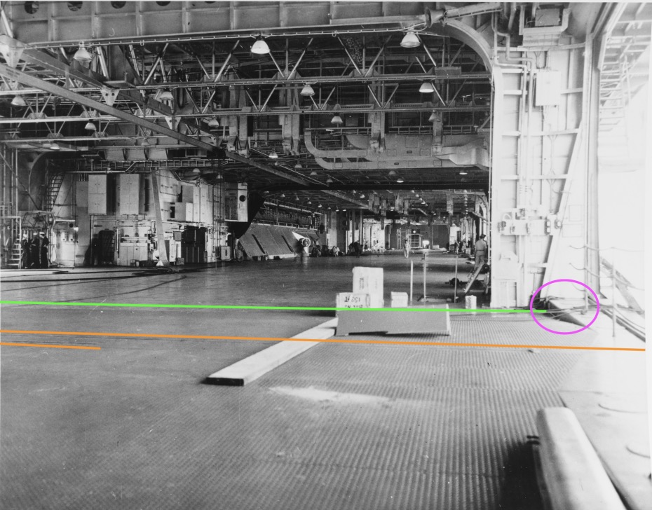
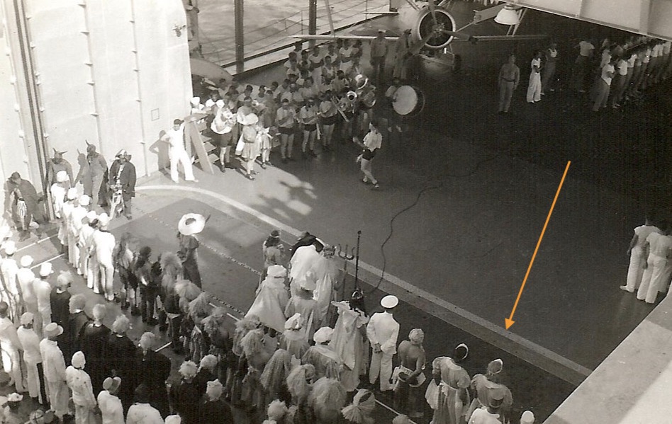
I still have to make the automatic safety rails at the back of the photo of the area only, you can see them clearly, as well as the Aux lift in high position. On the plan they are noted "automatic stanchions".
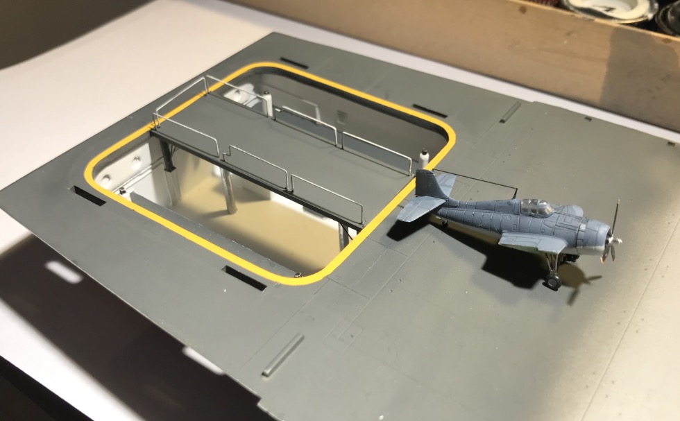
I painted a possible yellow line around the elevator location, I think you can see it (lighter paint than the hangar deck) on the photo taken of the flight deck (CV-6). The masking was sporty...
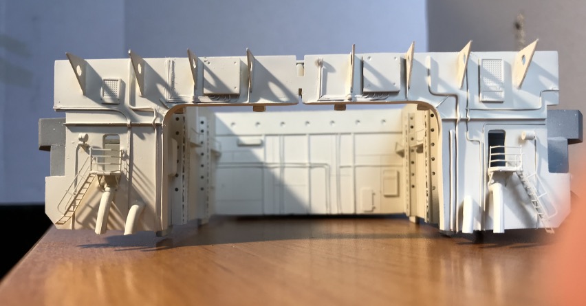
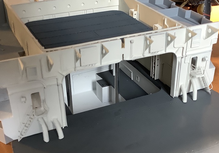
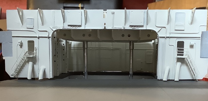
Now, it must have looked very much like this from the blueprints. No original photos from these angles unfortunately.
The "Canson" paper accommodations are not too bad, but I would like to improve them as well as make some other parts, for the elevators, other accommodations, the list is long...
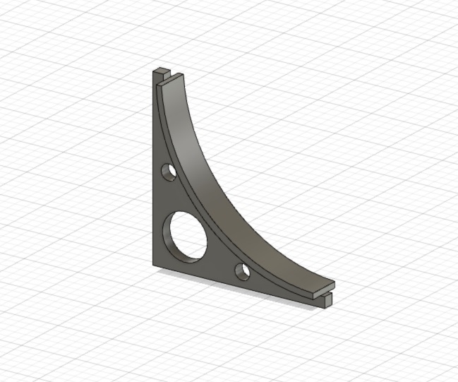
So I got interested in 3D modeling parts in order to print them in 3D with resin, this kind of printer being very precise, more than plastic wire. I ordered the printer.
It gives me time to familiarize myself with the 3D Fusion 360 software. It's English, but I don't mind, I found an American youtuber making very good quality beginners' tutorials.
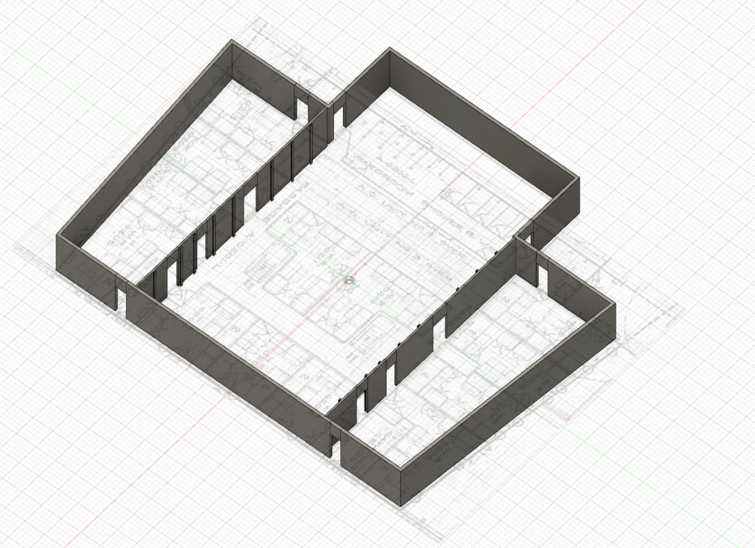
After 2 days of class, I manage to come up with things I like. So I'm going to be able to tweak the front moves by adding, furniture, cabinets, bunks and if all this work is presentable at the final print, I'll take apart what I did to replace this part.
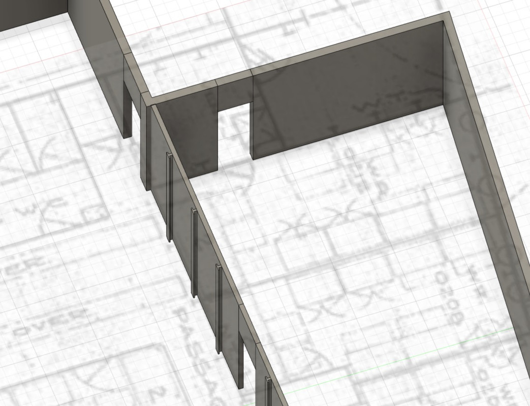
Here's what it looks like at the moment, it's not going fast, but it's going faster and faster now, when you understand how it works.
I put the shot from the Yorktown on canvas, which makes the 3D editing easier. Note that the angles of the trapeze of this front module are different on the plan and on the model, it was necessary to adapt.
The outer walls are 0.8 mm thick, the inner walls are 0.4 mm thick. The floor will have to be glued separately, as it would be impossible to paint it properly if it was integrated into the whole.
No porthole on this floor on the Hornet, removed versus CV-5.
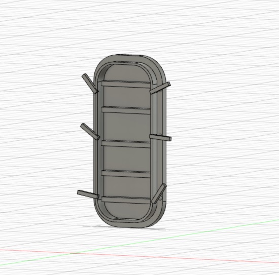
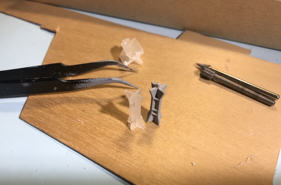
After a few disappointments of printing tests (The gallery of horrors), I'll explain , I finally managed to get some presentable things. It's by forging that we become forged...
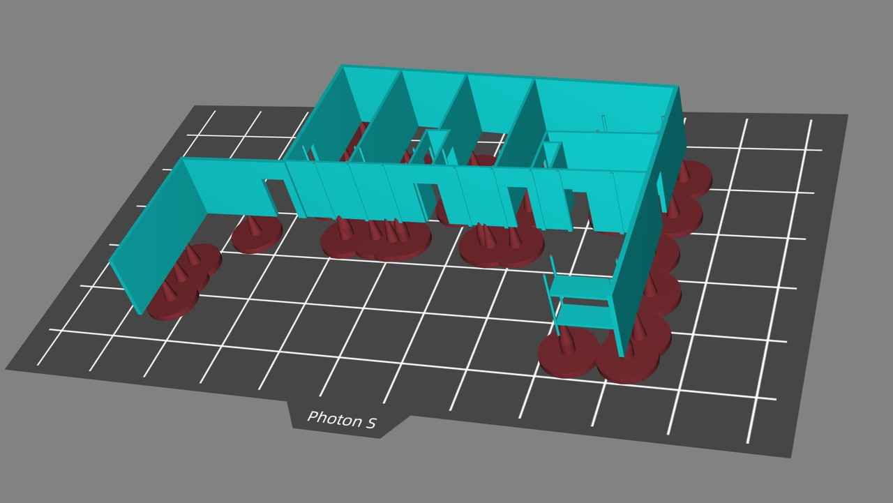
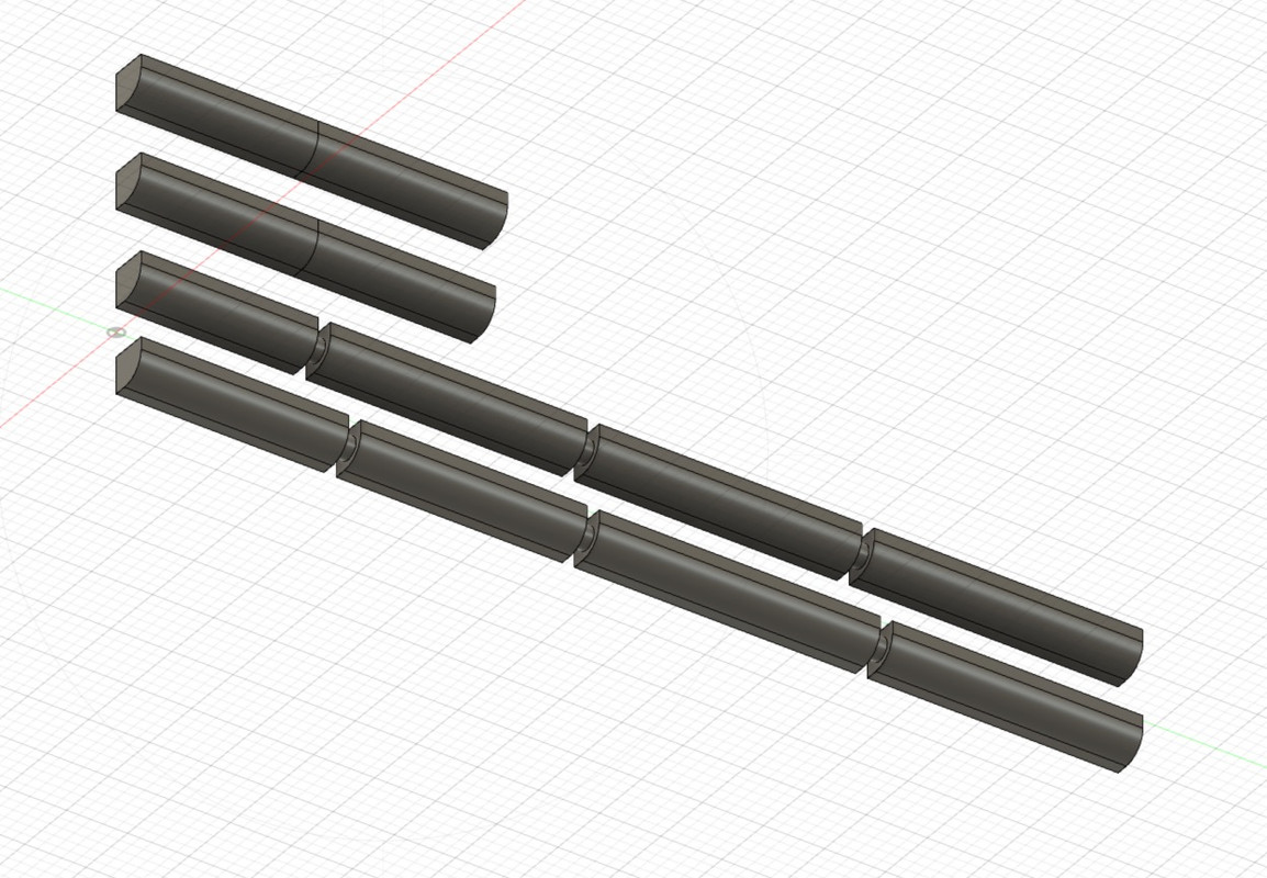
So I've lowered my ambitions to print my piece in one piece (Vertically) for the moment.
So I cut it in two, it will be easy to join and it will shorten considerably the printing time since the two pieces are 11.5 mm high when flat and the complete element is 75 mm vertically.
What counts for the printing time is the vertical, the Z-axis, count one hour of printing for one centimeter... I'll let you calculate...
Here's how it works.
My 3-D drawing isn't finished yet, but it's coming along nicely.
The progress in Fusion 360:
The "Slice" program of the printer that allows to design the file that will allow the printing of the 3D file.
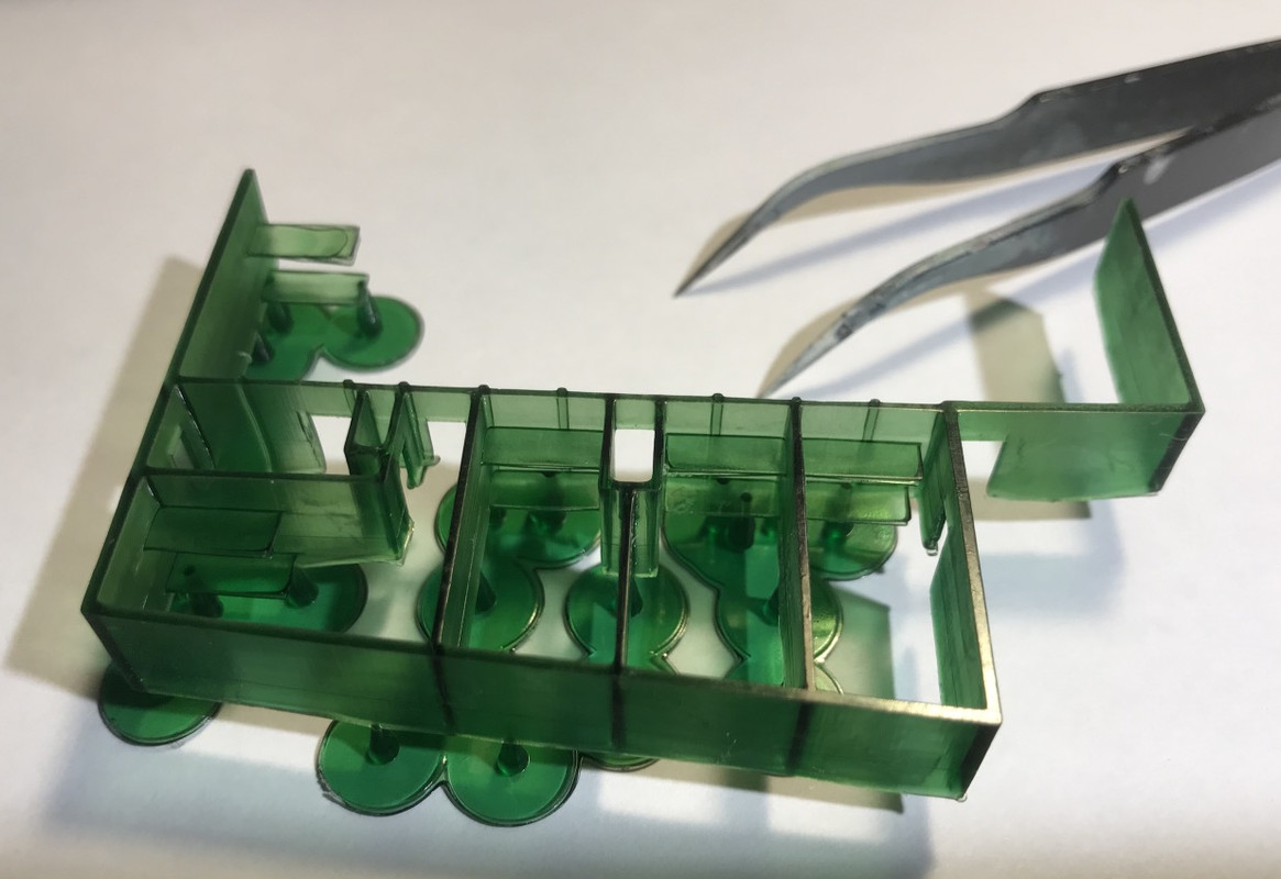
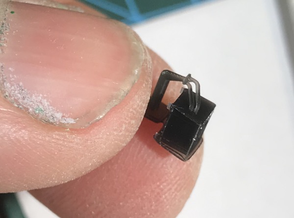
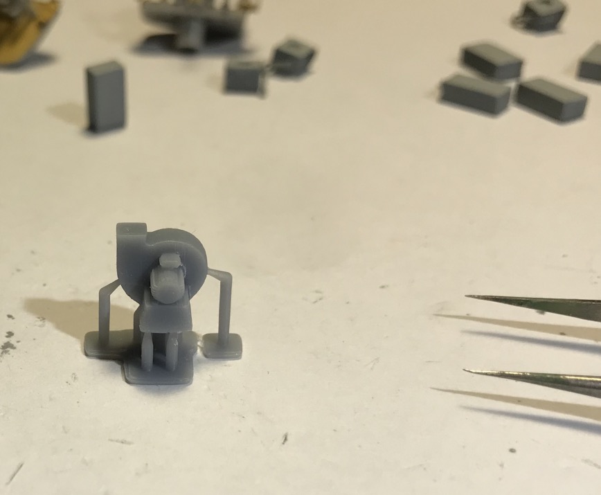
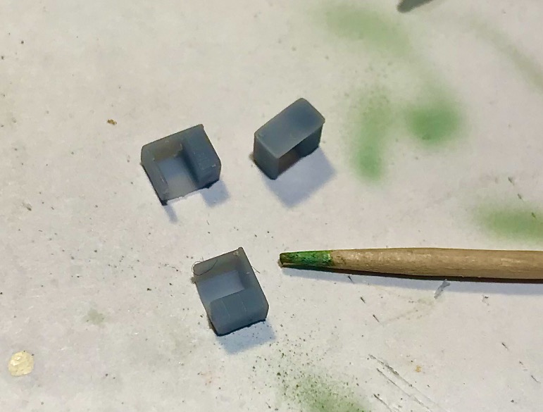
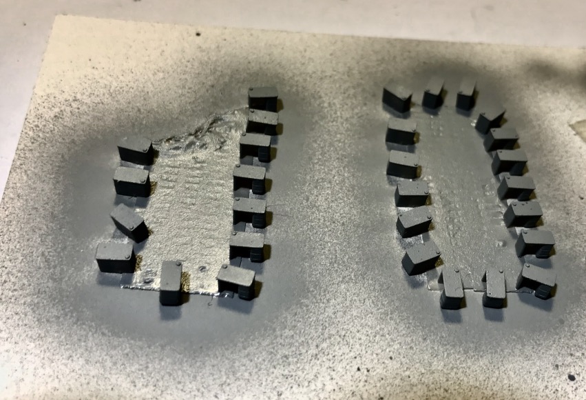
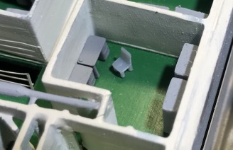
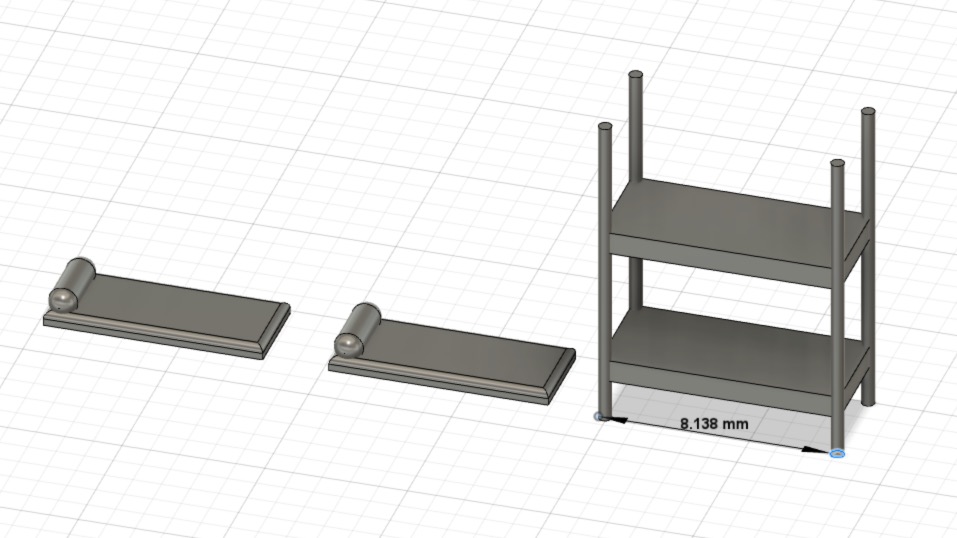
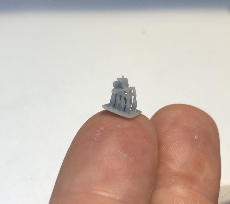
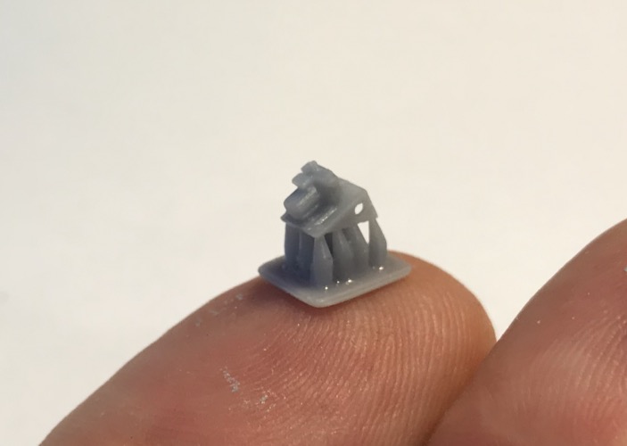
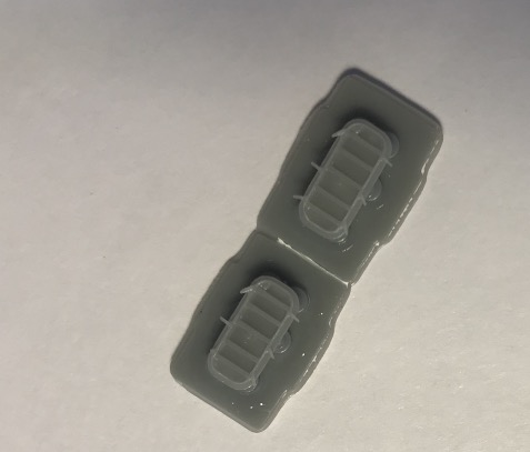
On the left is my first correct impression of the port forward deck without print support, a test. Booze cleaning of the room.
In the middle, the next impression with a support (the round studs), it's much better, cleaning with isopropyl alcohol, I save it because the liter is not given at the moment ( Covid stuff )...
On the right, the test cube, which must be perfect before starting.
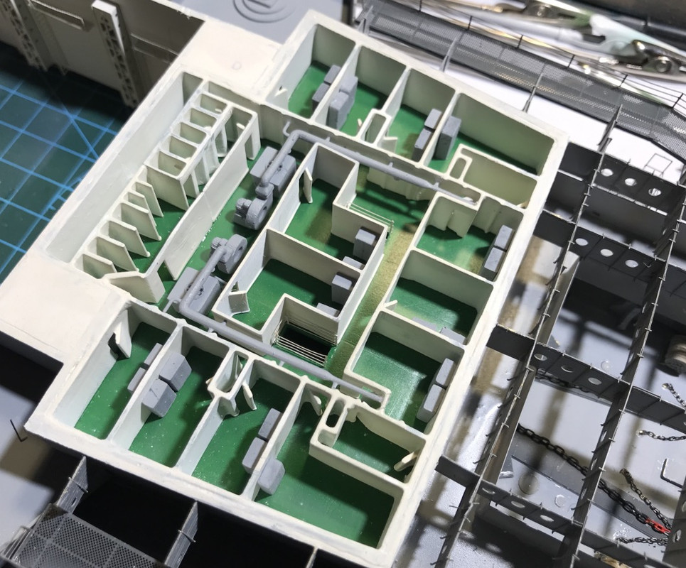
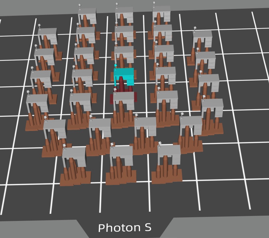
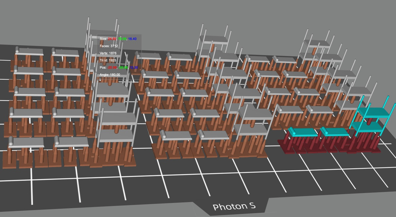
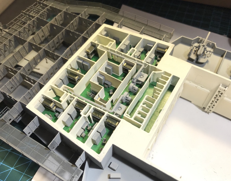
The 3D modeling of one of the forward crew quarters below the flight deck of the Hornet also took quite a bit of time to familiarize themselves with the 3D Fusion 360 program and the strict procedures for getting the best out of the 3D Proton S printer.
It's all very exciting, I must say, when it goes fast and in the right direction.
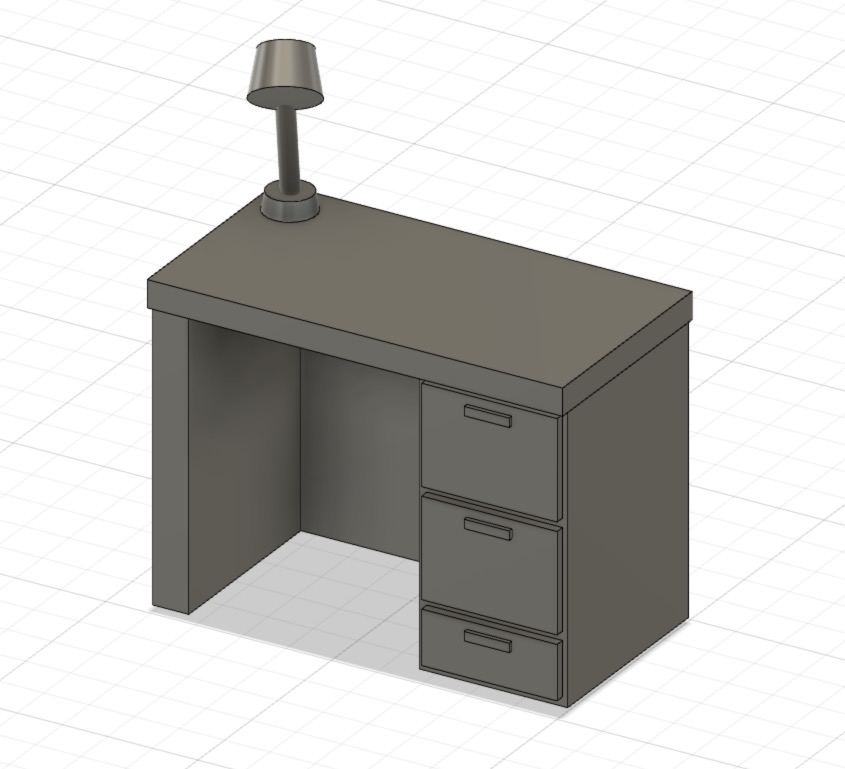
I've given up printing the bunks with the bulkheads, you lose precision and that causes problems with the paint and therefore the fine details. The beds are ready to be printed separately, in order to detail them a bit more, the rest of the furniture will follow, desks, cupboards and chairs if possible.
I'm pretty happy with the result, it fits in to within a tenth of a millimeter, it's pretty incredible. A real satisfaction after many hours of work.
I still have the floor to be printed, it's ready, as well as the central block of cabins, which is also separate.
The most tricky part was dismantling the old cardboard assembly...
All that's left is to paint it white!
3D printing of the floor will start, it will take 6 hours because it's hight.
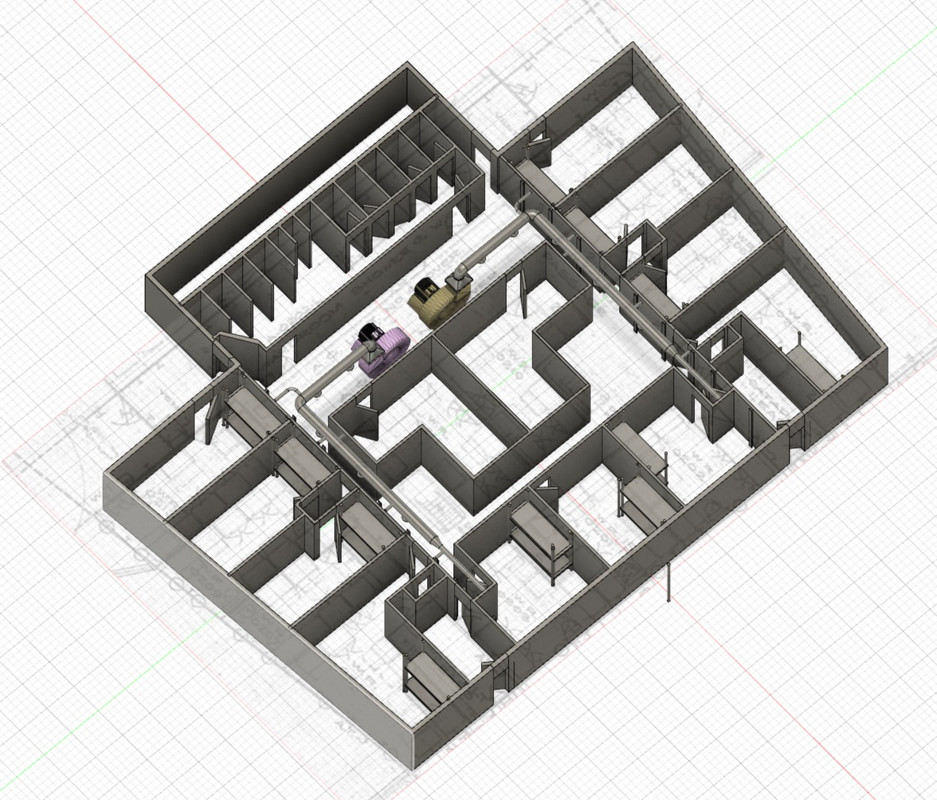
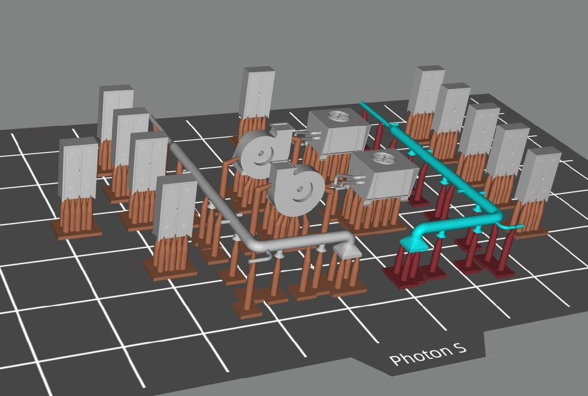
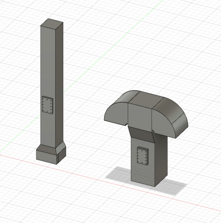
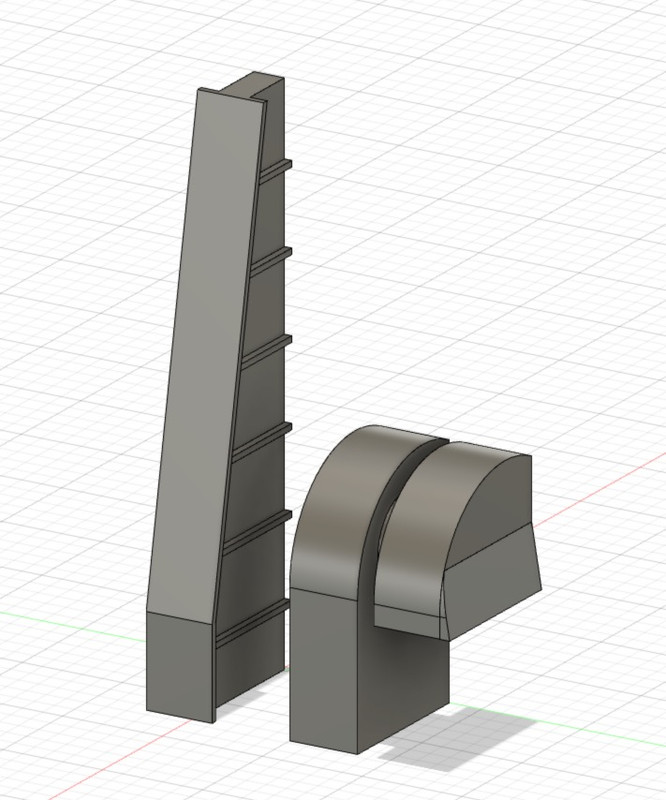
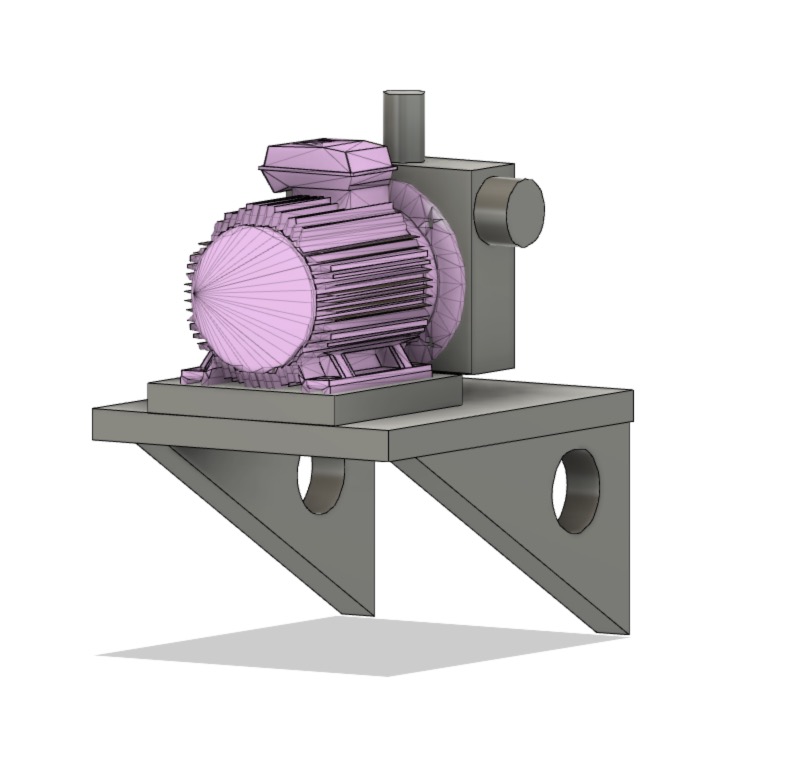
3D design of ventilation ducts, fans, fresh air unit.
Preparing the print file with the Photon S.
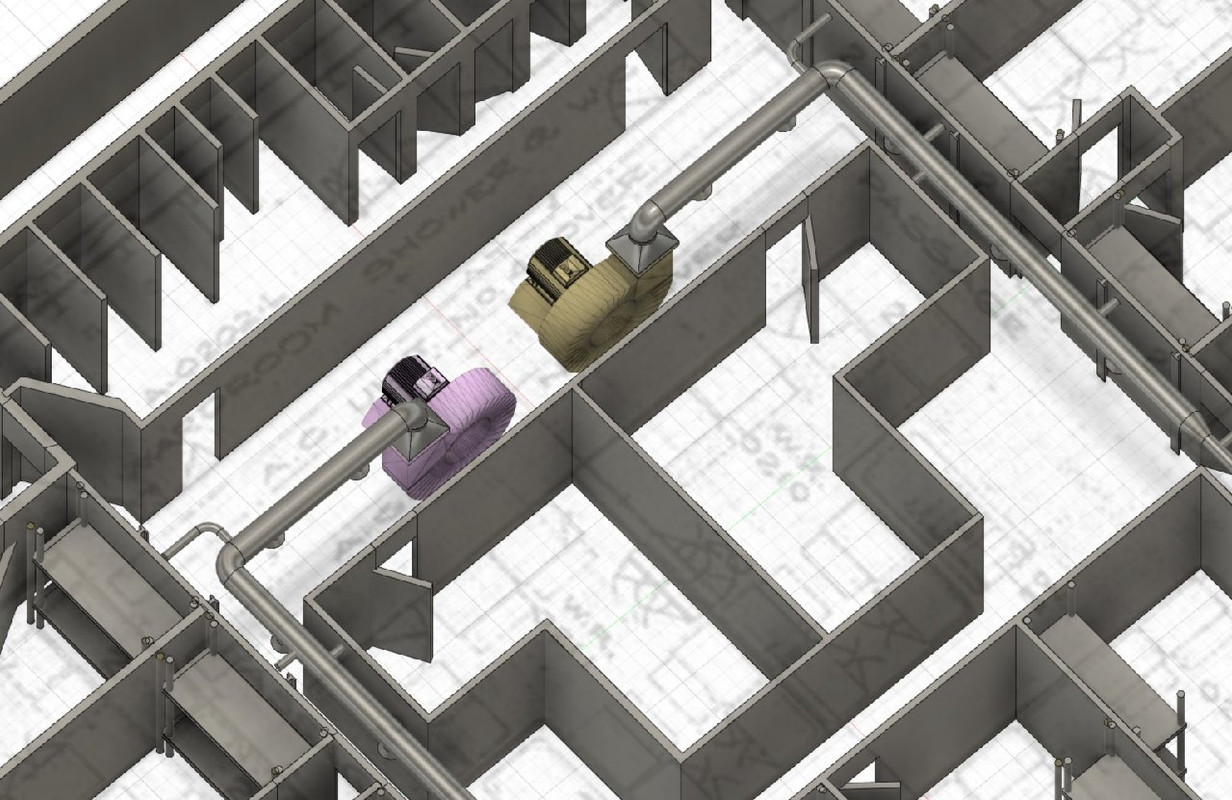
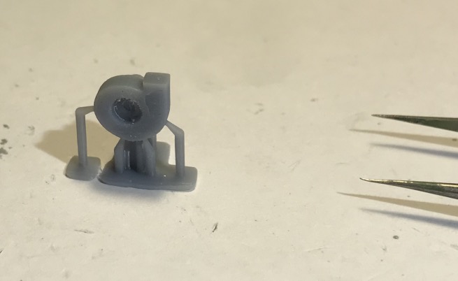
A printing test of an air conditioning unit, too small for me, I would make it bigger, but the details are there, you can see the two little pipes.
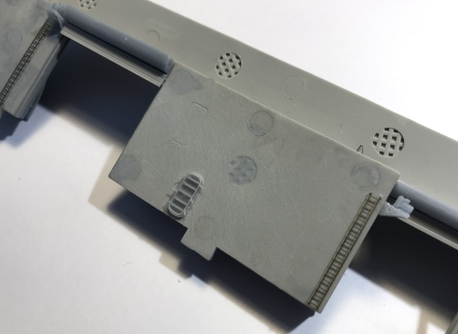
Large AA battery from the front platforms. Cabinets, and a test of moving fans. I finally got my gray resin. It greatly increases the details compared to the green one, it's impressive the difference in print quality. Good thing I finished the bottle of green. It's a pity I didn't receive it earlier, some details would have been much more present on the walls in particular.
Gluing the ventilation, air conditioning and cupboards, it's starting to look good, missing desks, benches and possibly chairs if I can print something presentable...
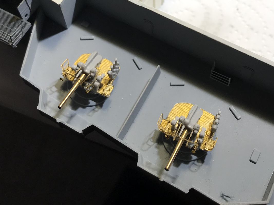
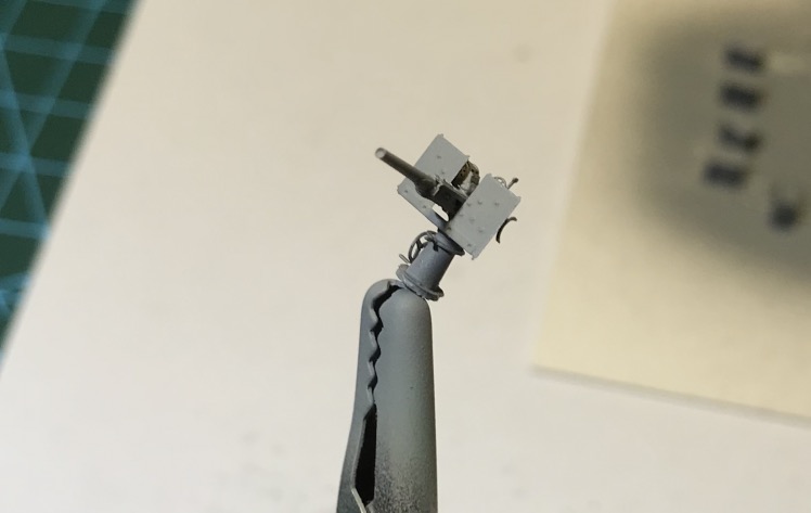
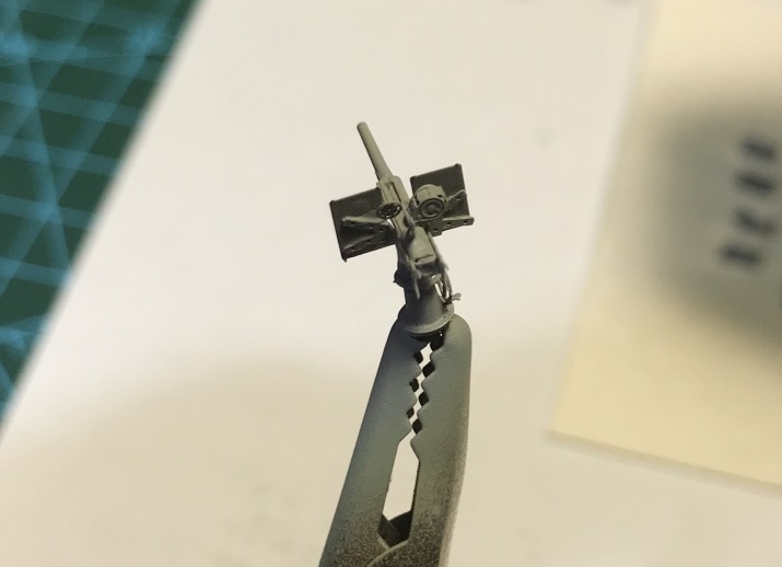
The Hornet was equipped with eight 5-inch (127 mm) / 38 dual-purpose guns and 16 1.1-calibre (28 mm) / 75 anti-aircraft guns mounted in quad (four guns working together).
It originally had 24 0.50 inch (12.7 mm) Browning M2 machine guns, but these were replaced in January 1942 by 30 20 mm Oerlikon anti-aircraft guns. An additional 28-mm quadruple support was later added and two more 20-mm anti-aircraft guns were added for a total of 32.
Joined: Tue Jan 11, 2005 1:40 pm Posts: 8174 Location: New Jersey
Wow. That is a crazy amount of detail!
Regarding the color profile you posted, the pattern on the island, especially on the port side, is incorrect.
_________________ Martin
"Tomorrow is the most important thing in life. Comes into us at midnight very clean. It's perfect when it arrives and it puts itself in our hands. It hopes we've learned something from yesterday." John Wayne
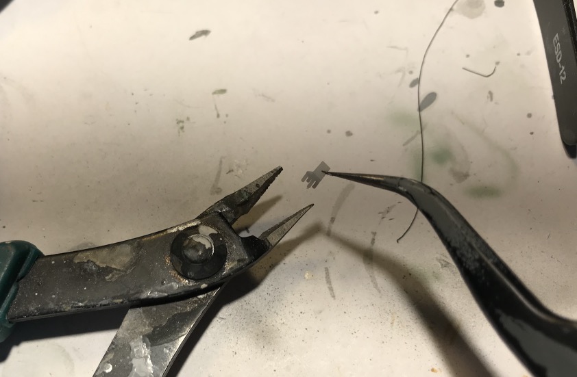
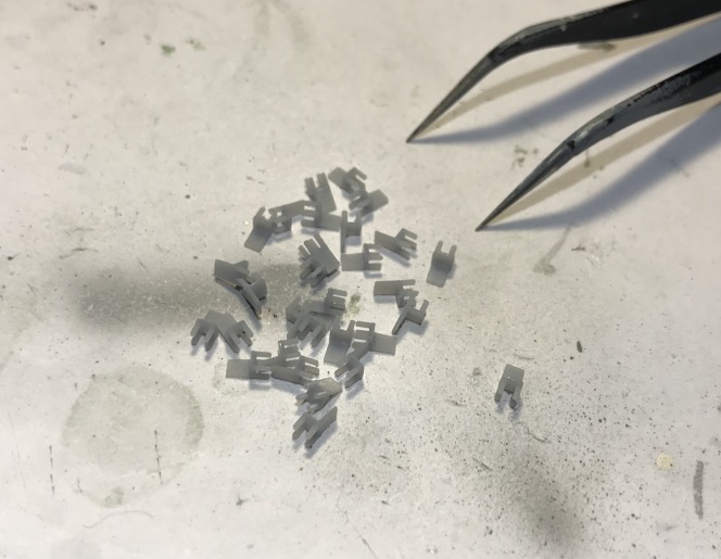
Manufacturing the desks, I simplified, because on this scale you have to do it to make something.
I'll need 30, please...
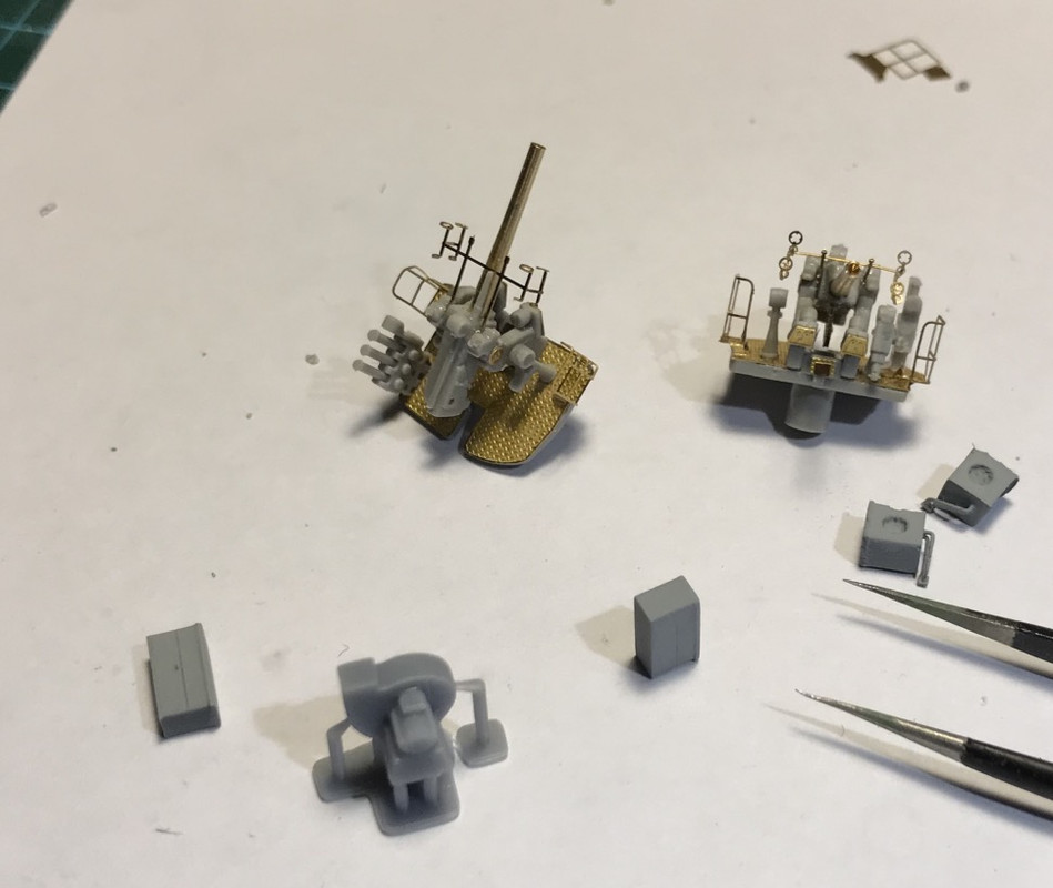
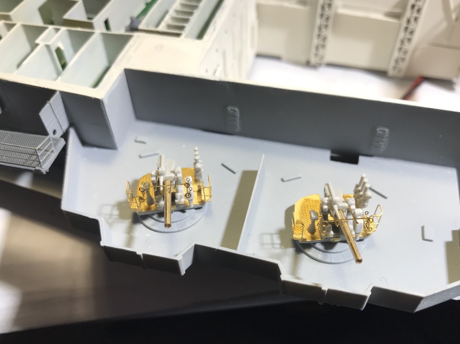
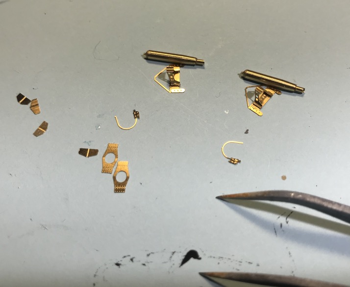
One of the 2 machine guns of the bow station, I'm missing some brass parts in the box, especially the 30 guns... For those two, I made do with what I had on board. I made a complaint to the kit seller:
This front block is almost finished, it's true that I didn't plan at the beginning of the editing to do so much scratching and modifications, which complicates the editing of some elements when it's not foreseen in the editing process.
The risk of damaging what has already been mounted is great, we all know that, the more the model advances, the more we have to be careful in our gestures and movement of the object.
For the details I will stop here, just the benches and chairs. It will be easier for the central part and the back, because I know exactly what I'm going to do.
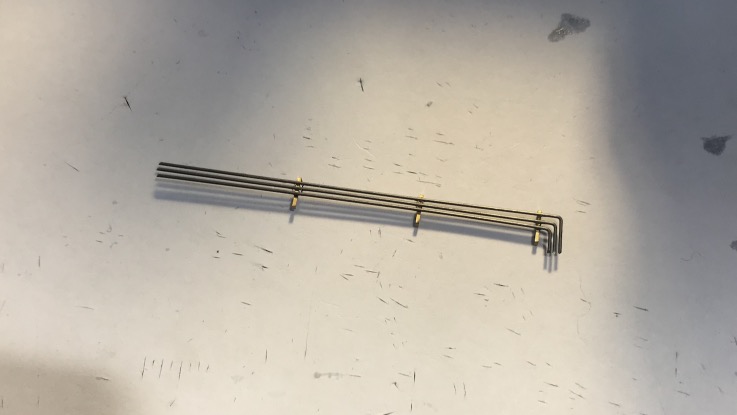
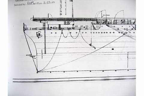
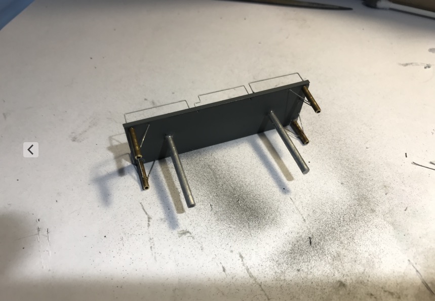
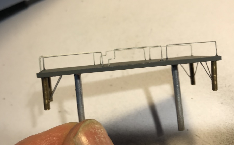
I've just mounted the masts for the paravanes with scratch, the steel cables have to be mounted.
Here on the CV-5 plan, we can see very well how the paravanes are rigged? It would be interesting to reproduce this rigging, a plate will have to be added at the bottom of the bow.
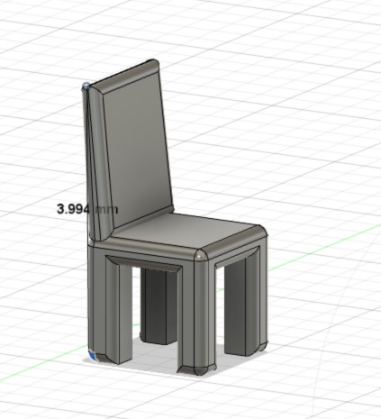
I made a basic chair.
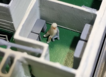
I've just put the final touch (finally!) on the forward crew station.
I've printed the beds, they are in two parts, the mattress and the bolster, and the two beds canvas and tubes. The tubes are 0.3 mm, the size of the smallest standard piano wire, this printer is really incredible.
May 26, 2020:
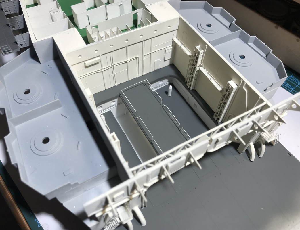
Installation of the hangar side catapult rails:
Installation of the fishplates on each side. Anthracite paint.
I've started the starboard forward bulkhead of the hangar.
Having some great HD pictures of this side of the ship, you can zoom right in, and I found a few small errors. I was able to correct some of them, but the main one would require too many modifications, so I'm dropping it.
You can see that the bulkheads are not accentuated enough on the model.
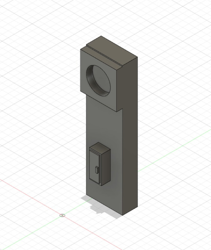
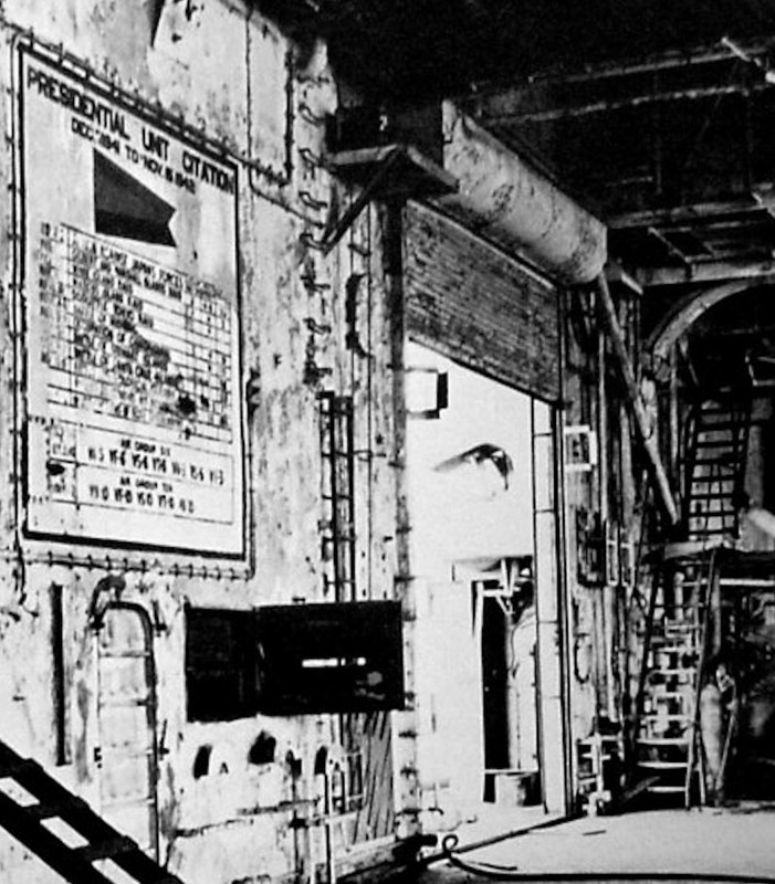
On the other hand, I modified the pseudo ventilation system of the hangar. I put the original mount as planned, compared to the photo, the electric motor is missing, and the box under the motor that connects the fan to the rising duct.
The electrical cabinet is too small, and one is missing on the back, the one that is on an angle...
Impossible to put this last one, the stall is not good, and there is no place for it.
Once modified with my freshly printed parts. I also added some unplanned PE, ladder and platform to access the electrical cabinet.
I also added the two missing IPN (Structure).
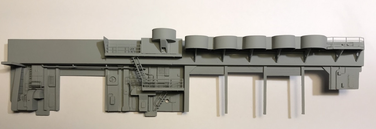
That's what it looks like :
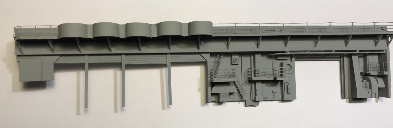
Merit's assembly:
Hornet:
Once modified with my freshly printed parts. I also added some unplanned PE, ladder and platform to access the electrical cabinet. ( one structure element is inverted on picture, that was modified later)..
A few bridges to mount in perspective...
A lot of upgrades installed, then painting:
Portside bulkhead.
I just added two IPNs for the moment, I need to find some documents on this side...
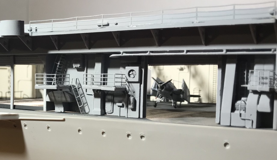
Starboard with the flight deck in position ti check adjustment and just for fun.
Port side in progress.
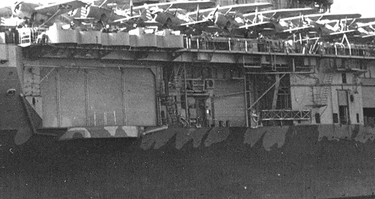
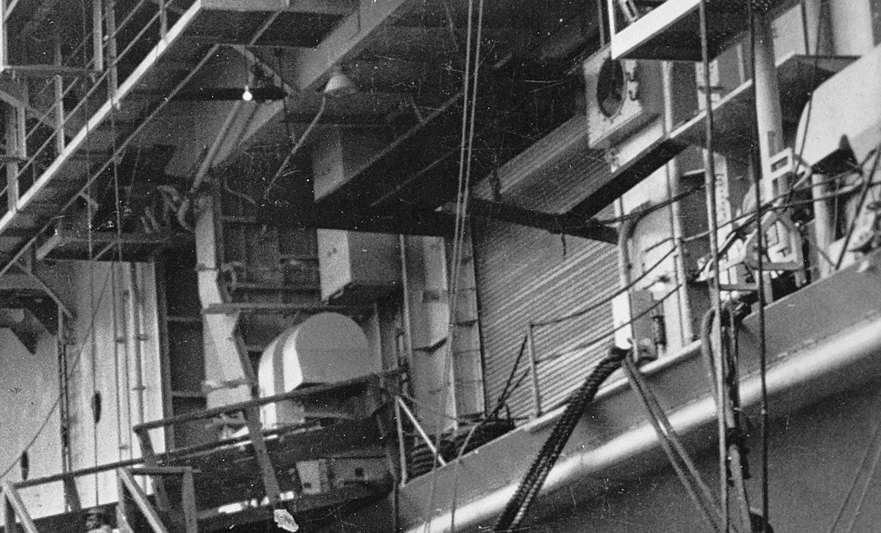
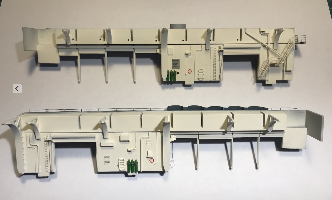
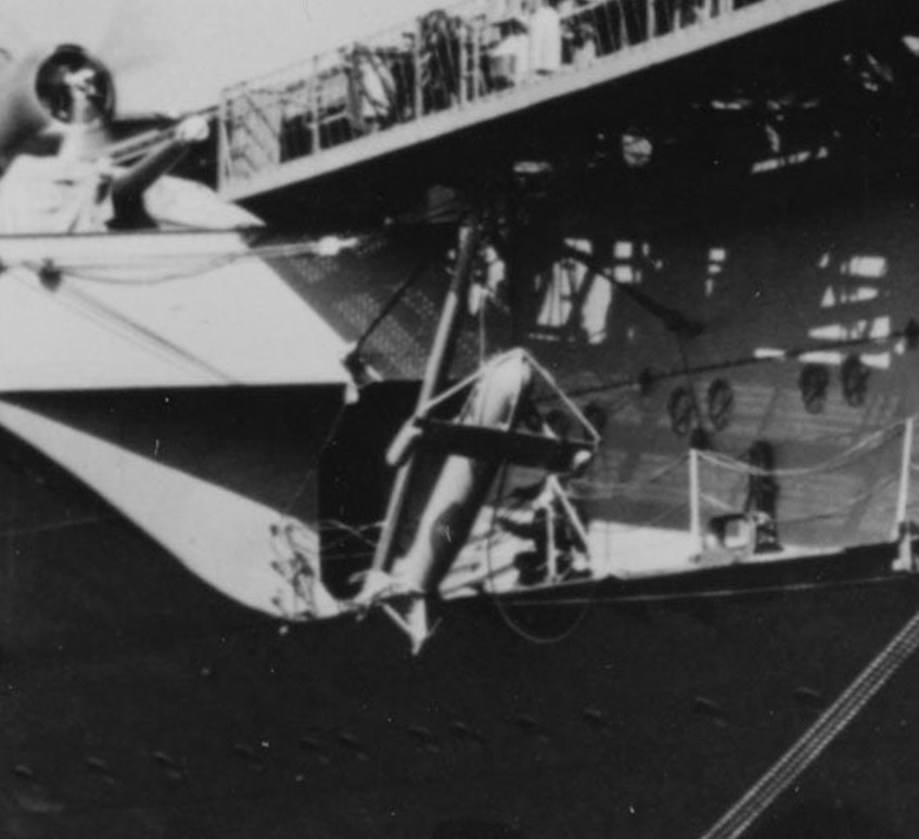
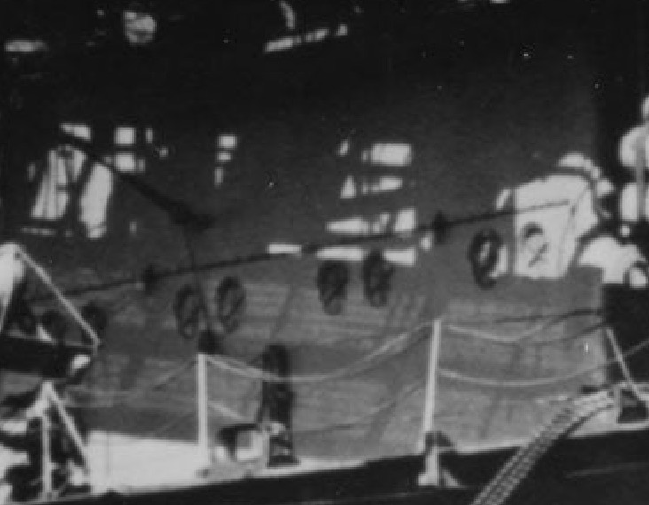
If we look closely at this HD photo of the Hornet alongside, probably in February 1942 like the other one, we notice that the first block with 4 sliding doors, is almost identical with starboard, not at all on the model. The ventilation duct placed at the back of this block is identical to starboard, the cut at the seagoing station prevents us from seeing the bottom, the fan.
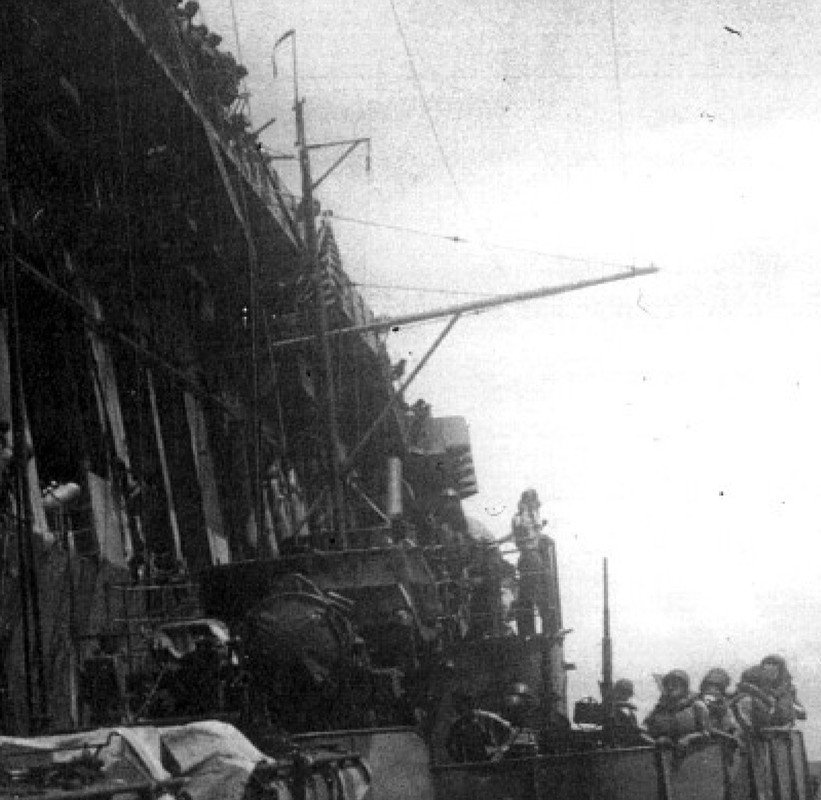
We also notice two small very thin masts in IP beam on the sliding door n°1 and in front of the opening of the biggest one the N°4. These two masts are emergency BF radio antenna masts that can be deployed on port side only, and all along the hull.
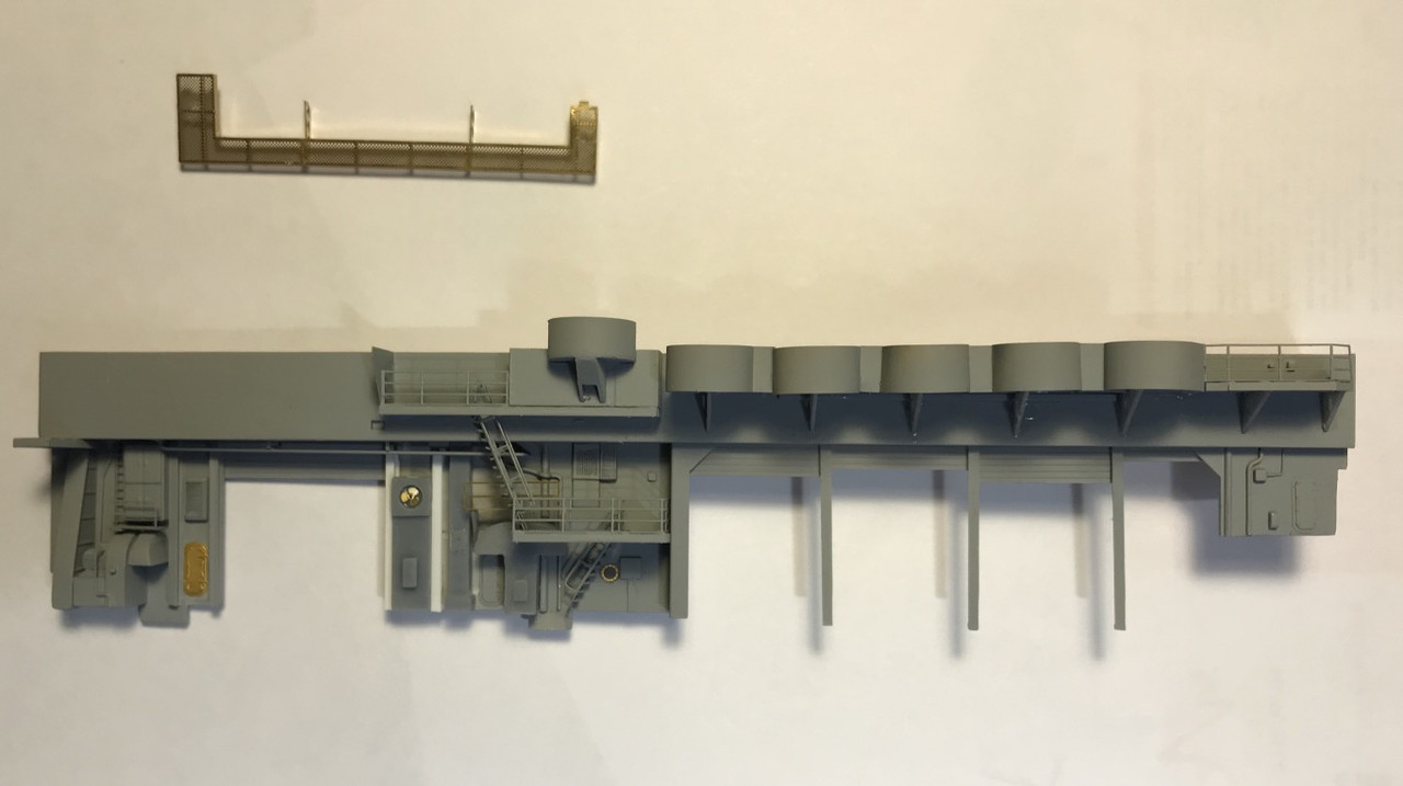
Merit's configuration:
While searching on the net , I found details about what seemed to me to be load masts, were in fact the gallows of the BF radio emergency antennas, in case those of the island would be destroyed. It's specified on the plans of the Hornet CV-8 that I would like to acquire, but unfortunately, the founder of the Maryland Silver site that sold them in the USA died in 2019 and his site with ... RIP.
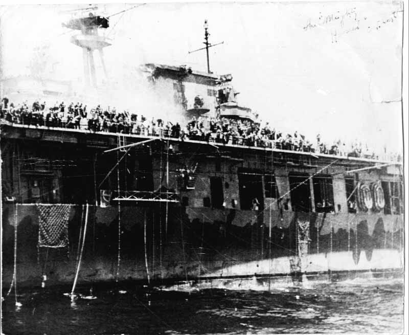
They are clearly seen here during the rescue attempt of the Hornet by the USS Russel (CD-414), which is placed on the port side and berths the Hornet, the sea is calm. 26 October 1942.
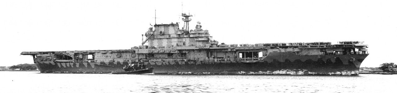
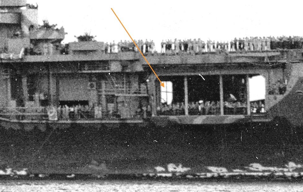
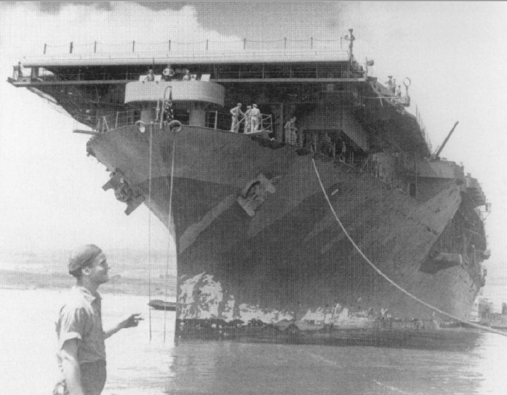
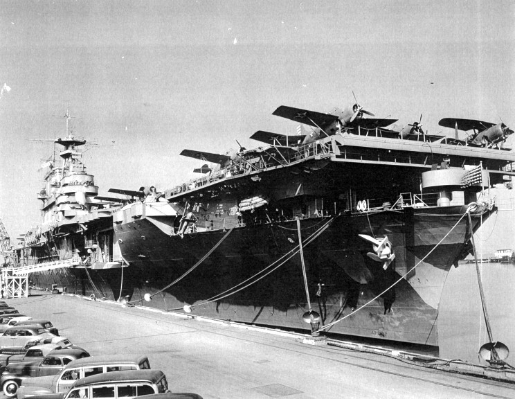
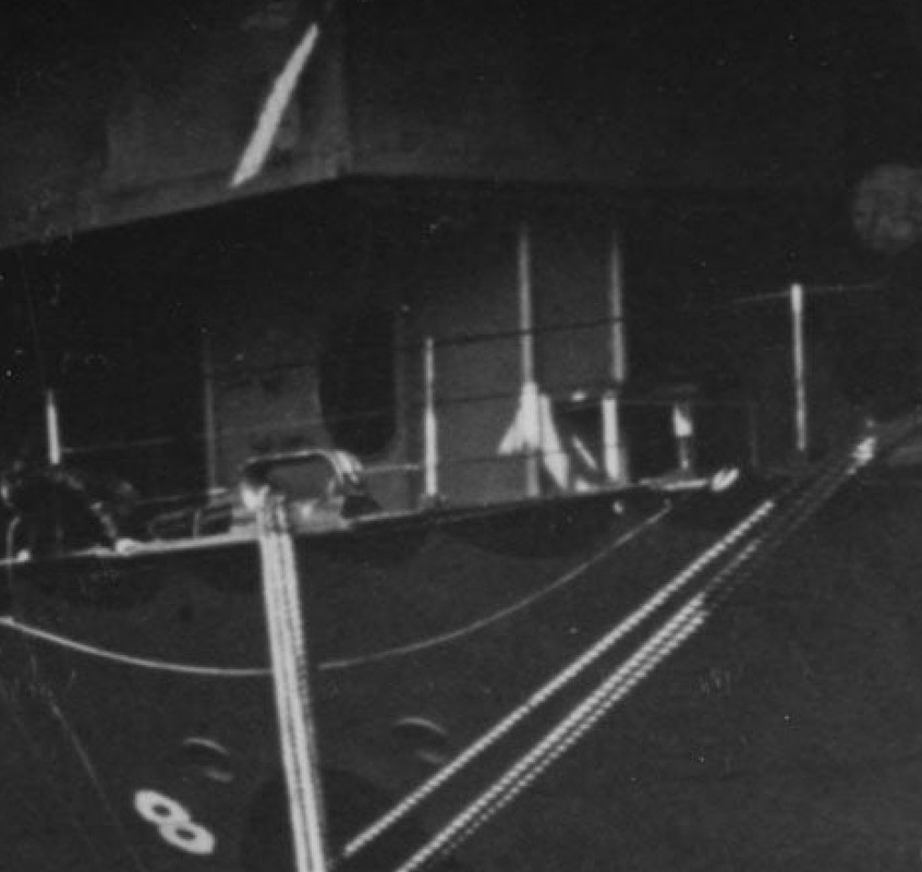
On this other HD photo taken when the Hornet arrived at Pearl Harbor, we can see through the starboard doors of the empty hangar (the planes must have reached the Pearl base.) the port door n° 4, and the famous sloping pipes and the radio mast which is therefore placed in the middle at the level of the port gangway.
26th May 1942:
Zoom in:
This is all I found on the internet about images of this CV-8 Hornet plan, if anybody have one to sale..:
Thanks to a lot of photo documentation, I arrive at a configuration of the places probably quite faithful by dint of cross-checking, but it still lacks data, we make do with it:
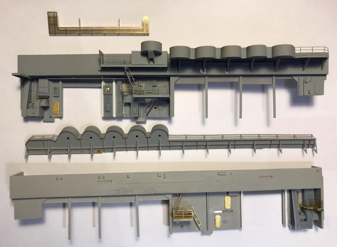
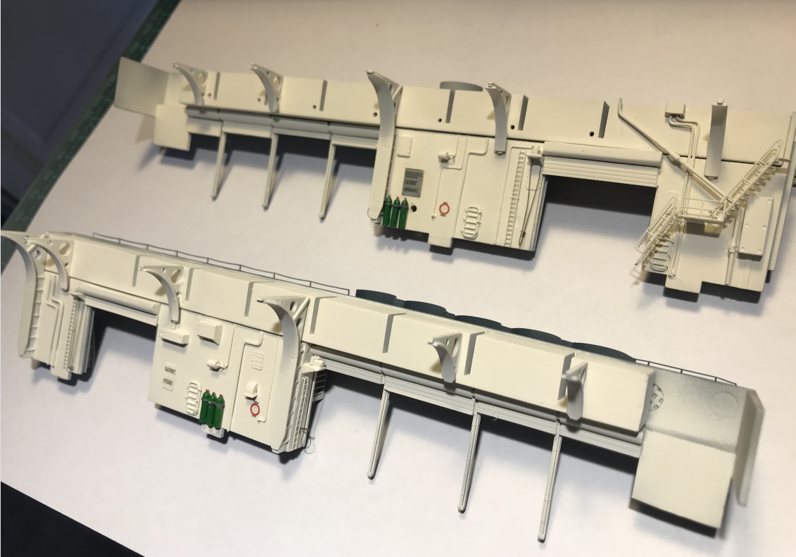
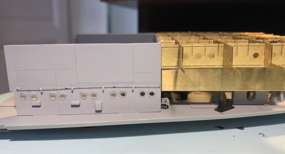
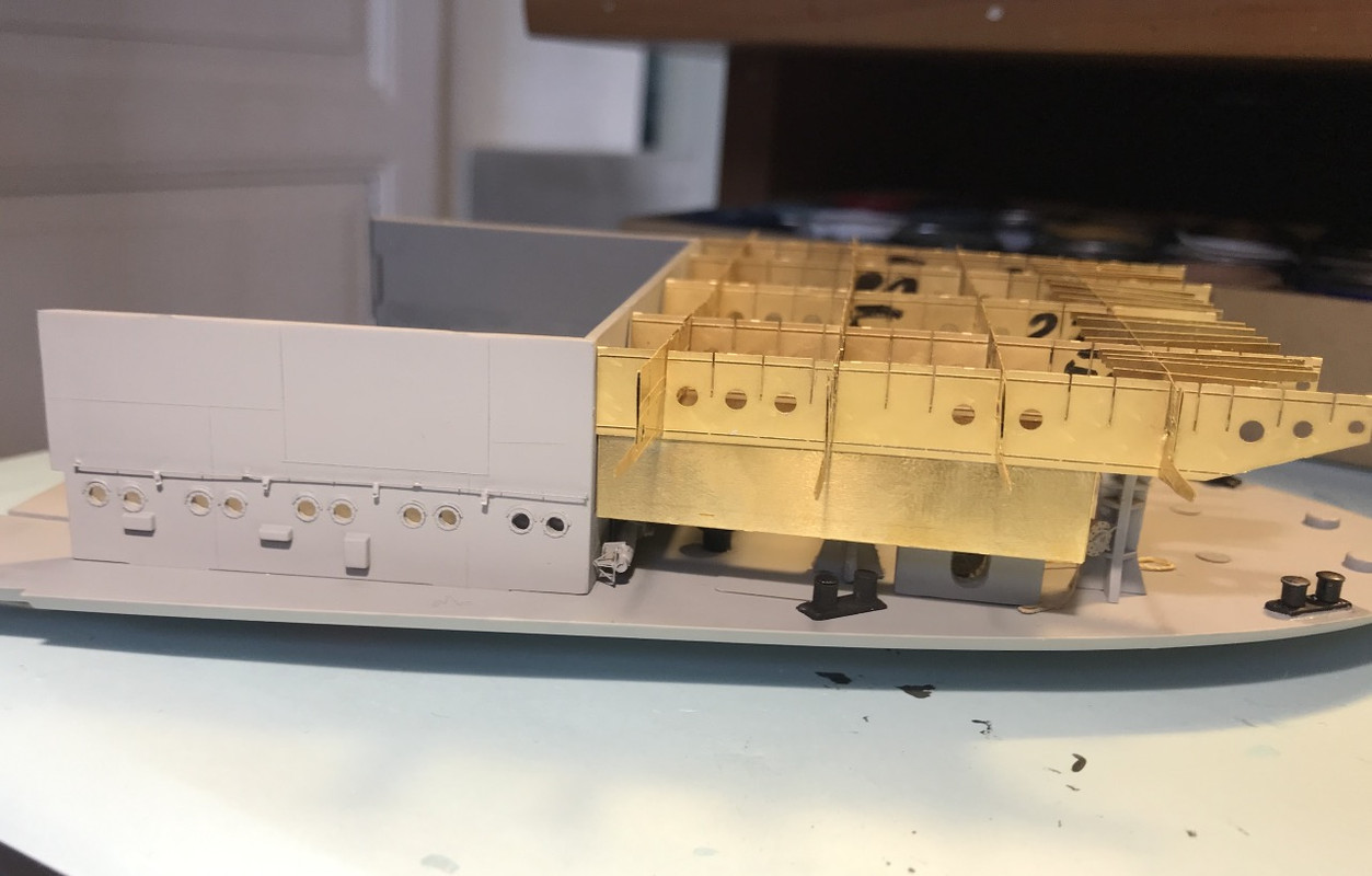
Port bow, hangar doors 1,2,3,4:
I've made copies by recreating starboard side pieces, fan ruffles, and the large vertical structural brace, I've printed several copies while I'm at it... I had already printed several copies of the electric motor and the electrical cabinet. I added some PE, ladder and platform and reused the existing PE. I still have a lot of accessories to create and print for that corner... LF Antenna masts.
I made the structural reinforcements for the AA platform and gangway, port and starboard, there are two types. Plus a few lines of pipe that I will use later, but not much better for the latter.
Starboard bow, hangar doors 1,2,3,4:
I came across this very good quality hd photo of the starboard bow that I'd had for a few days but I hadn't thought about zooming in. The Hornet is being finished at the yard.
You can see very well the aft fan of the area, and especially the radial fan with precision which is at the front mon so much of the 4 td door. Moreover one can see that a small platform without railing is present near the main platform of the stairs.
So I went back to my editing, took off or erased a lot of things! (It's getting complicated, it was almost over... In this case you have to take a thousand precautions to avoid damaging anything, taking your time is the key word).
Merit turned it into an L-shaped platform, which I took out of the way... I cleaned up this portion, removed one of the 2 portholes, moved one, a door that does not exist. I modeled the ductwork and its radial fan, then printed it out. ( one structure element is inverted on picture, that was modified later)..
Creation of copies of identical parts for mainly port side, structure, fan.
Port forward:
Starboard forward:
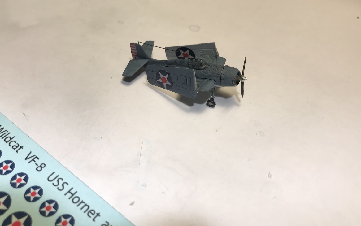
Wildcat, set offsets for April 1942.
Thanks to my friend Bruno (Bgire on this forum) for printing them out for me, otherwise I don't know how I could have gone on with the authenticity.
They are superb, so small, and so easy to install. A matt veil will be sprayed to protect them and integrate them even more after a new touch of patina.
There are 29 Wildcat's left to decorate at this time, only 4 are built! There are still 61 planes to be mounted, Devastator, Dauntless and 64 delivered to be glued ... + sixteen B25 Mitchells to build, paint and decorate.
A crazy thing. My parking lot is going to be busier than the runway parking of airports during Covid...
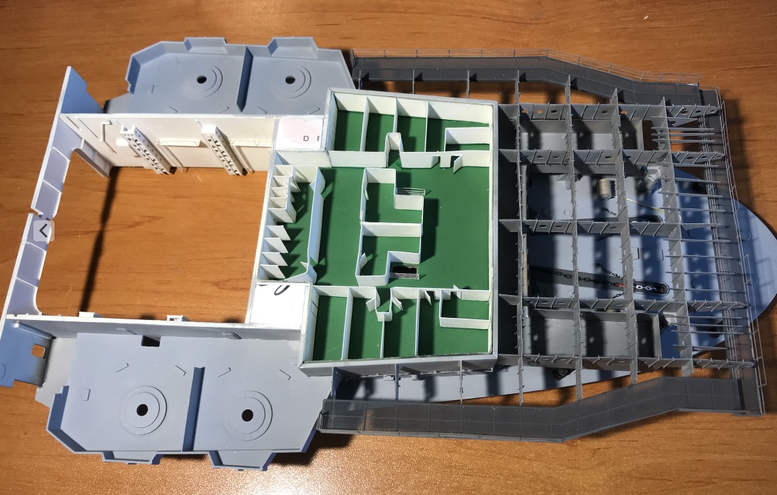
I started inside the forward hangar, the bulkheads. It's a lot of work because it's not really supposed to be visible from above.
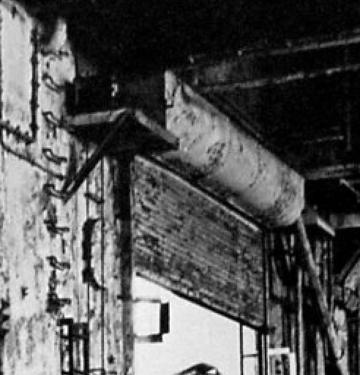
On this picture, which is worth gold because there are few of them, of the Big E hangar (USS Enterprise, during its demolition), we can see the rollers of the side metal curtains as well as the electric motor and its gearbox. A ladder provides access for maintenance and repairs.
You can also see the door and the only porthole that I've already put back in the right place outside. I have a waterproof back door to make.
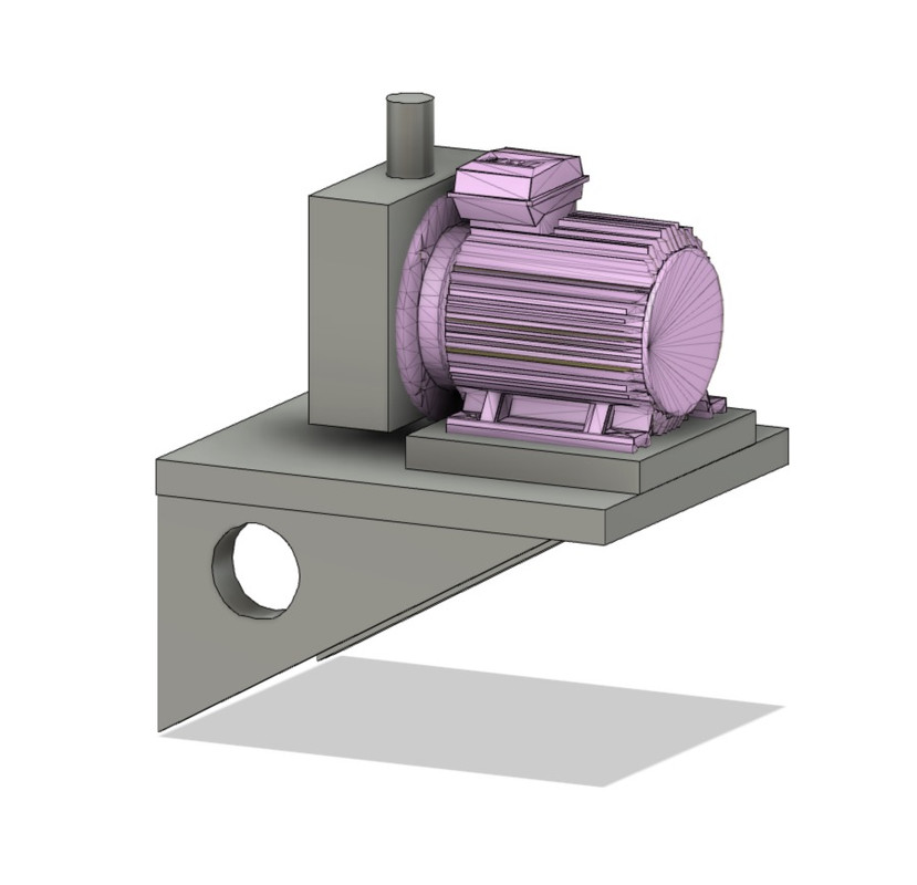
Modeling of motor, gearbox and support.
The rolls of the curtains, the different curtains are not the same size on the port and starboard sides
The motor, it's really small...
Manufacture of watertight doors, structural elements. Little scratch and photoengraving.
The top caissons are not glued, they are in fact fittings. They will be used to hide the resistances of the LEDs, hence the holes to pass the wires.
I used these two pictures of the CV-6 and CV-8 hangar to help me:
I still have 3 more bottles, maybe some nitrogen to stick on the bulkhead, i don't know, it comes with the box.
I'm still working on the front walls of the hangar but it's finished, I add details, either I extrapolate from the photos, or I unfortunately invent to furnish the hangar.
The documentations are relatively weak on the hangar of CV-8, but by searching frequently on the internet we can find informations here and there on the English forums.
This ship didn't have a long career in wartime versus the Enterprise and the hangars obviously didn't inspire Navy photographers, fortunately "Life" magazine took some nice ones.
I finally got the green light to glue the front block to the hangar. Periodically I put the whole thing on the hull to check that there are no deformations at the level of the recesses between the two, so as not to have any bad surprises, and the same goes for the flight deck... It would be too complicated later on to correct certain errors.
A very nice and imaginative job on a fine and heroic ship. A friend of mine, a BM1 when I knew him, as a young man in 1941 was assigned to the newly commissioned Hornet right out of boot camp. He served the whole year she was in commission and said with a wry smile, "first ship I walked off of and swam off of". Her air group's performance at Midway wasn't spectacular but Captain Mitscher's reputation survived.
Love the internal detailing! And yes, photography always reveals any imperfect work we may have done!
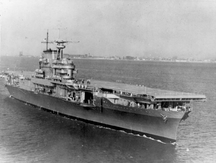
Interesting in one of the earlier photos Hornet is carrying SB2 "Helldiver" biplanes, replaced with SBD's on the West Coast before proceeding to the war zone. The Air group was also equipped with the new F4F-4 Wildcats, the most obvious difference was the folding wings. The previous F4F-3 did not have folding wings. Because of the increased aircraft weight, the performance was considerably poorer. Not considered an improvement by the Naval Aviators who flew them.
A very interesting book covering the early carrier combats is Lundstrom's " The First Team".
This one?:
Wildcat was a "small fighter",manual retracted landing gear etc.. But;
"The Grumman F4F Wildcat was an airborne fighter used by the US Navy and the Royal Navy. First used in combat by the British in Europe, the Wildcat was also and especially used by the Americans in the Pacific theater in 1941-1942.
The Wildcat was outclassed by the Mitsubishi Zero, its main opponent in the Pacific theater, but it still managed to prevail, mainly due to its ability to take damage. Relatively well armored and equipped with self-sealing tanks, the Wildcat was able to survive numerous impacts inflicted by the Zero, to the surprise of the weakly armored Zero.
Japanese ace Saburo Sakai describes the damage tolerance of the F4F as follows:
"I had full confidence in my ability to destroy the Wildcat and decided to finish off my enemy with my 7.7mm machine guns alone. I turned my 20mm guns off and moved my 20mm guns closer to my target. For some strange reason, after I fired about 500-600 rounds into the Grumman, the aircraft did not fall but continued to fly. I thought this was very strange, it had never happened before, and I got so close that I could almost hit the Wildcat. To my surprise, its daggerboard and ailerons had been ripped apart. With an aircraft in such a state, it was not surprising that the pilot was unable to continue the fight! A Zero that would have received so many bullets would have long since been transformed into a fireball. »
On wing carriers, the Wildcat was replaced in 1943 by the larger Grumman F6F Hellcat to face the Zero. However, the Wildcat was still manufactured by General Motors under the acronym FM for use on escort aircraft carriers where larger, heavier fighters could not be used. It was to be replaced by the smaller Grumman F8F Bearcat to standardize fighter models between wing and escort carriers, but the latter did not enter service until after the end of the Pacific War."
Users browsing this forum: No registered users and 44 guests
You can post new topics in this forum You can reply to topics in this forum You cannot edit your posts in this forum You cannot delete your posts in this forum You cannot post attachments in this forum


 Thanks Dan!