Slowly backwards, but the work goes forward!
I messed up a bit yesterday when I put my structural reinforcements from the flight deck into the forward garage. I'm beginning to understand the philosophy behind this hangar ceiling, which is heavily loaded with all kinds of scrap metal... It's better, as there are still tens of meters to go to the stern and a mistake made at the bow will be difficult to make up for later.
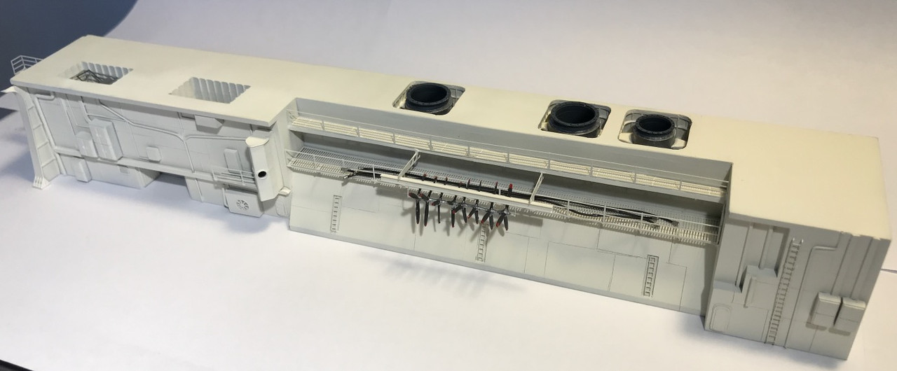
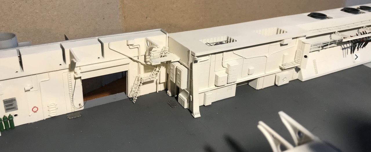
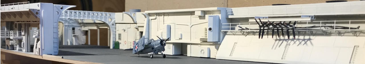
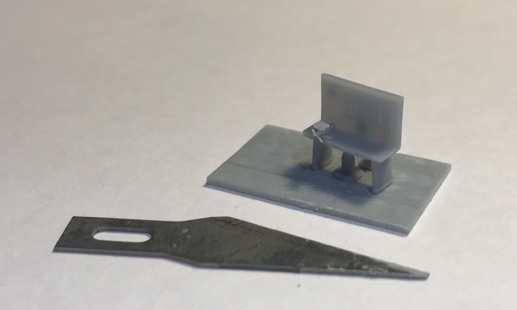
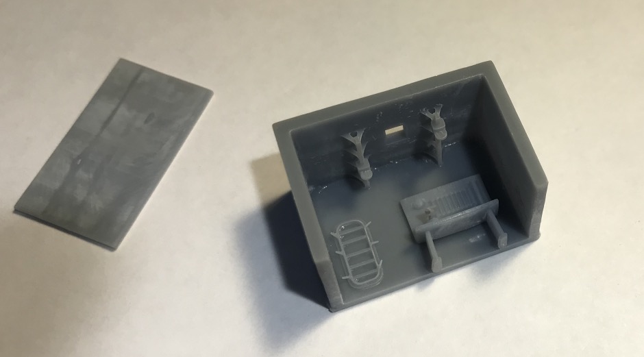
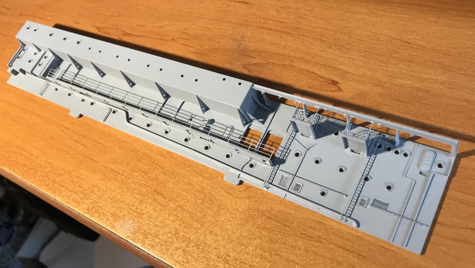
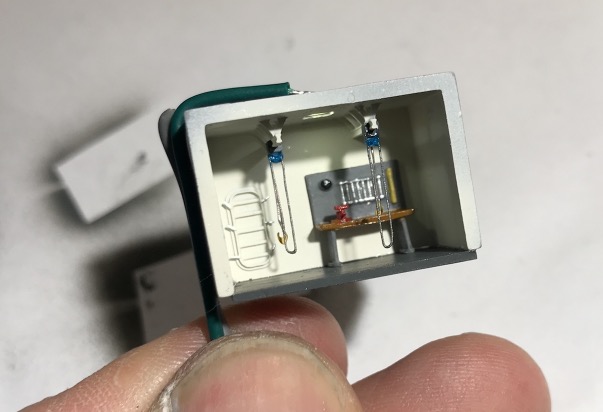
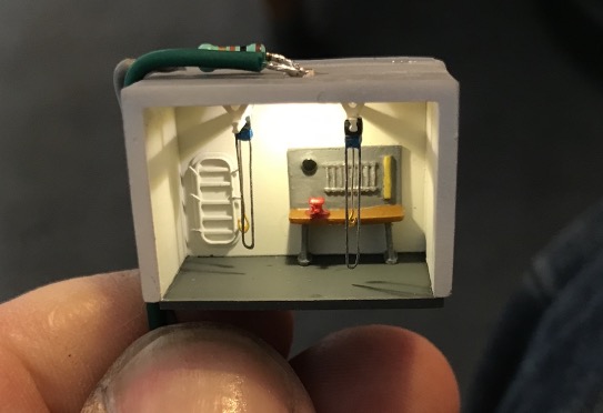
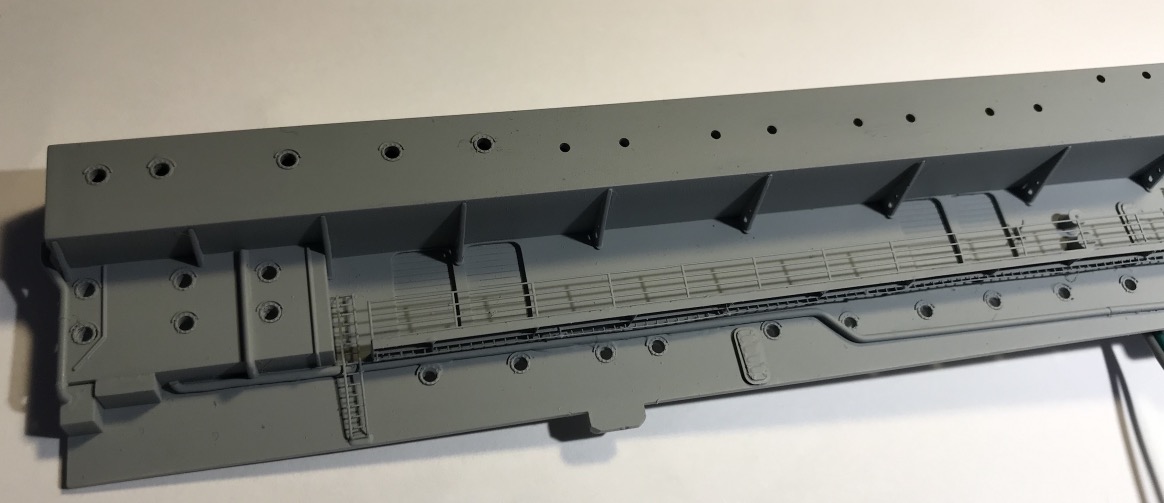
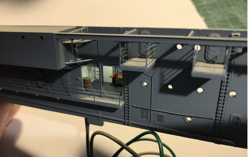
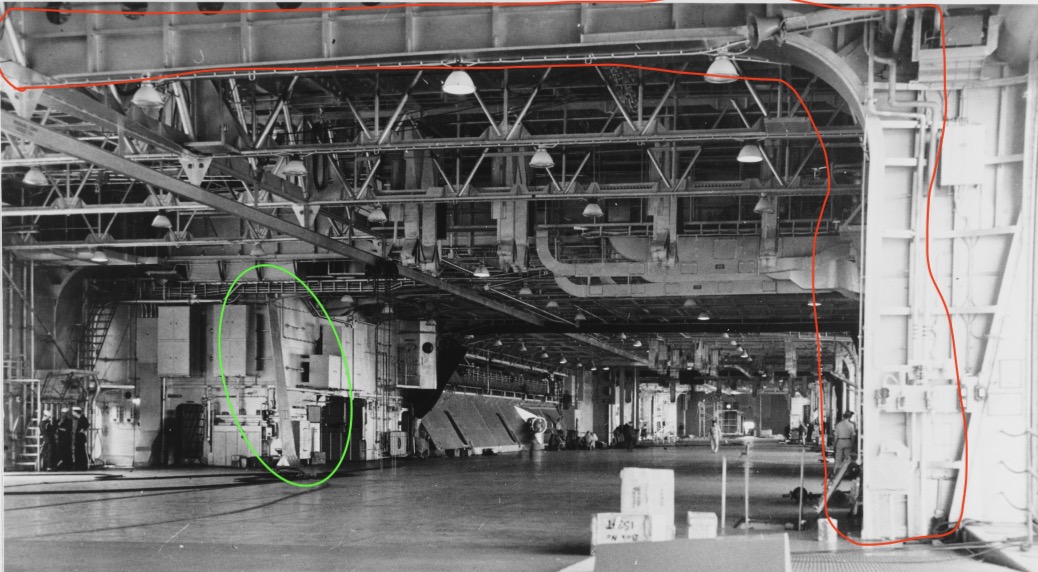
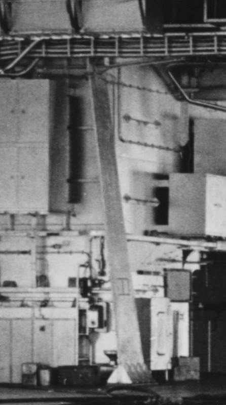
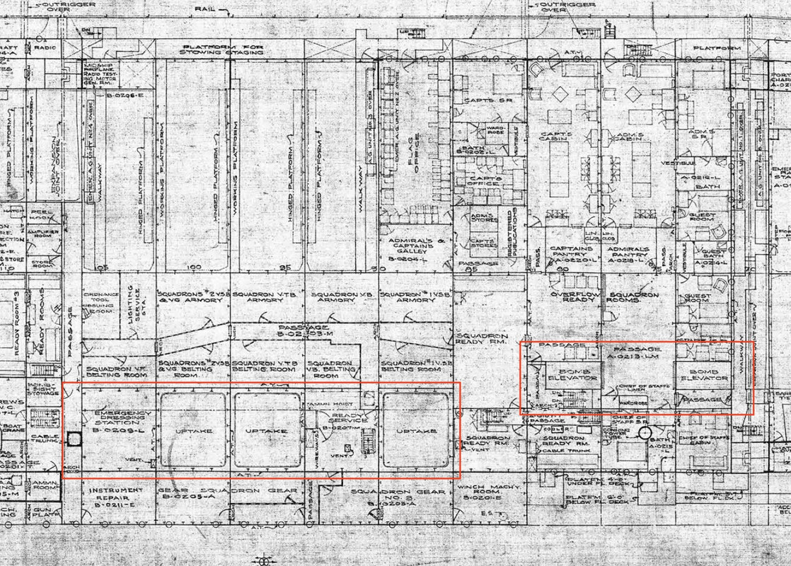
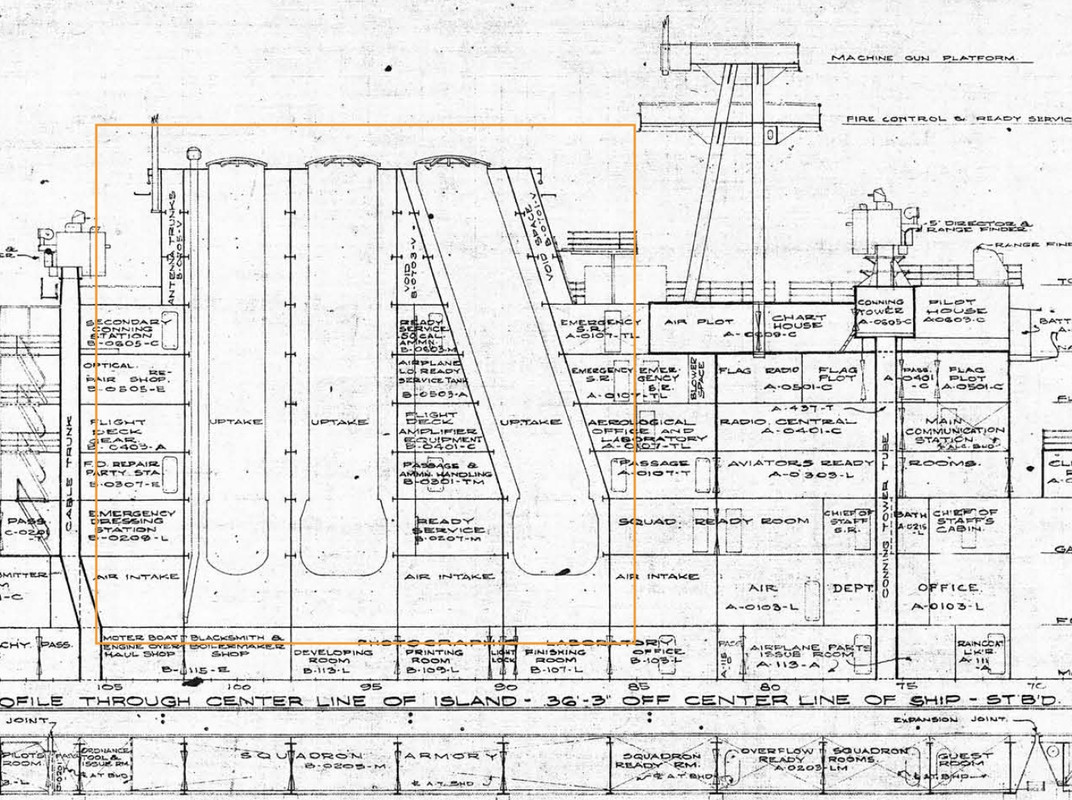
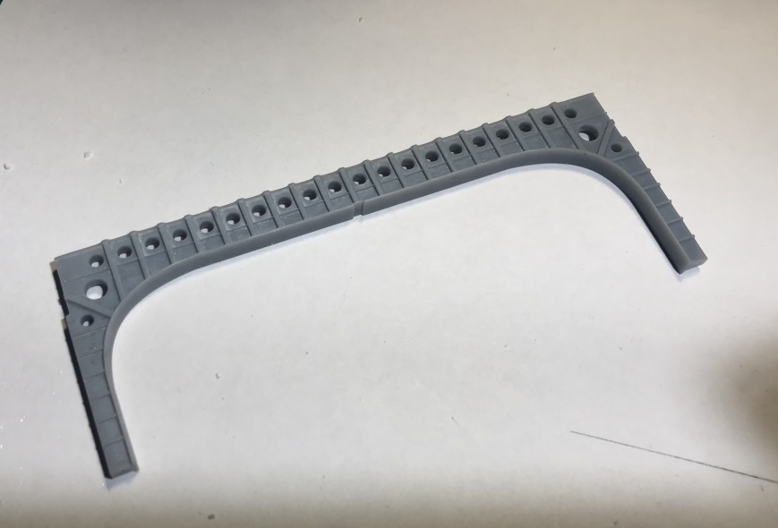
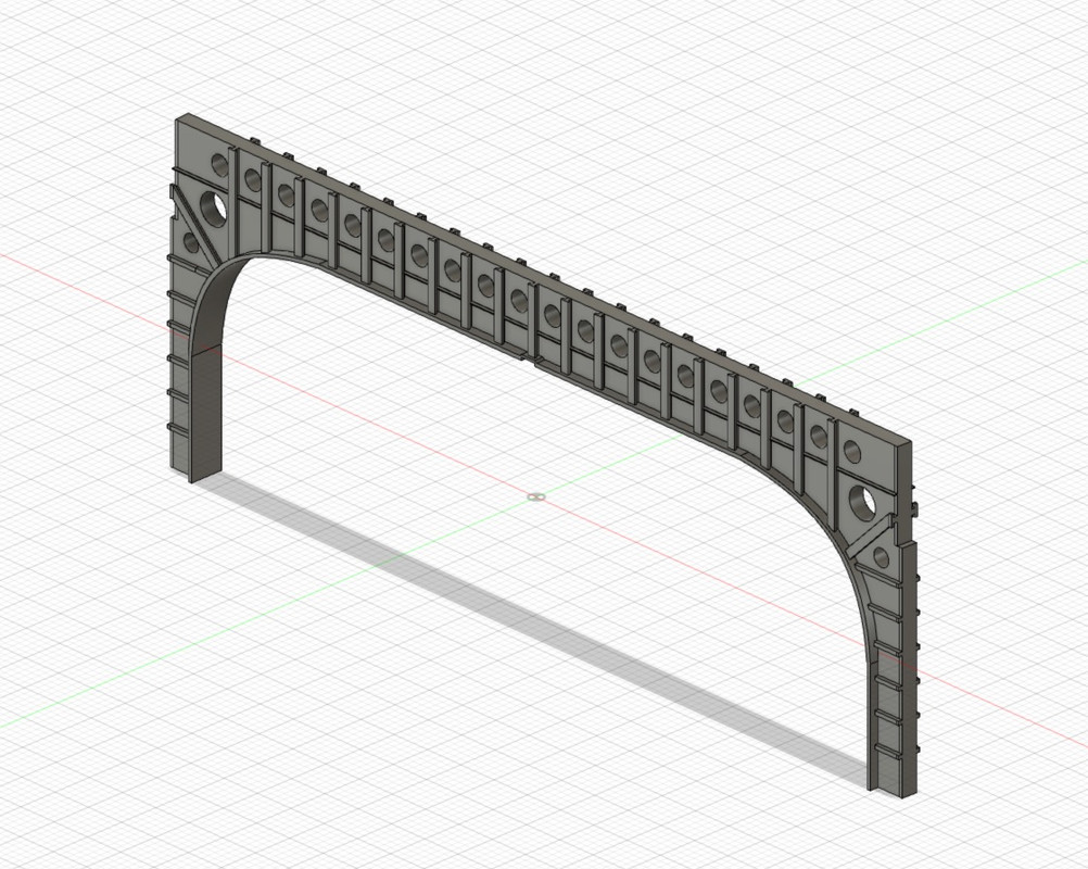
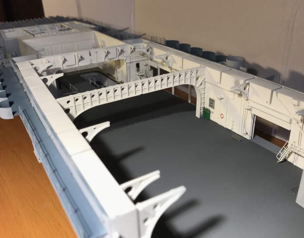
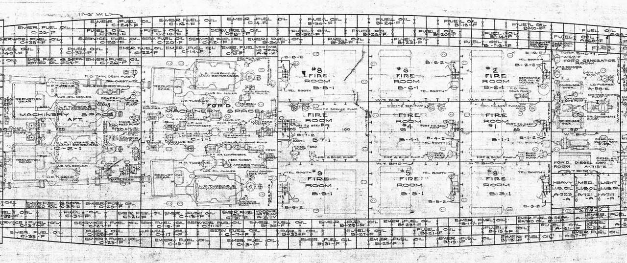
We see surrounded in red one of the main couples supporting the flight deck, there is another support at the level of the bomb lifts. We see it on the green picture, bolted to the ground. Its shape is nice to make.
I made this beautiful masterpiece very wide, it brings a lot to the details of the hangar, there will be others more back to design.
It was necessary to glue the bulkheads before installing this piece. The pt and sb housings are still removable, to install the LED wiring. I already passed the main wires to Sb.
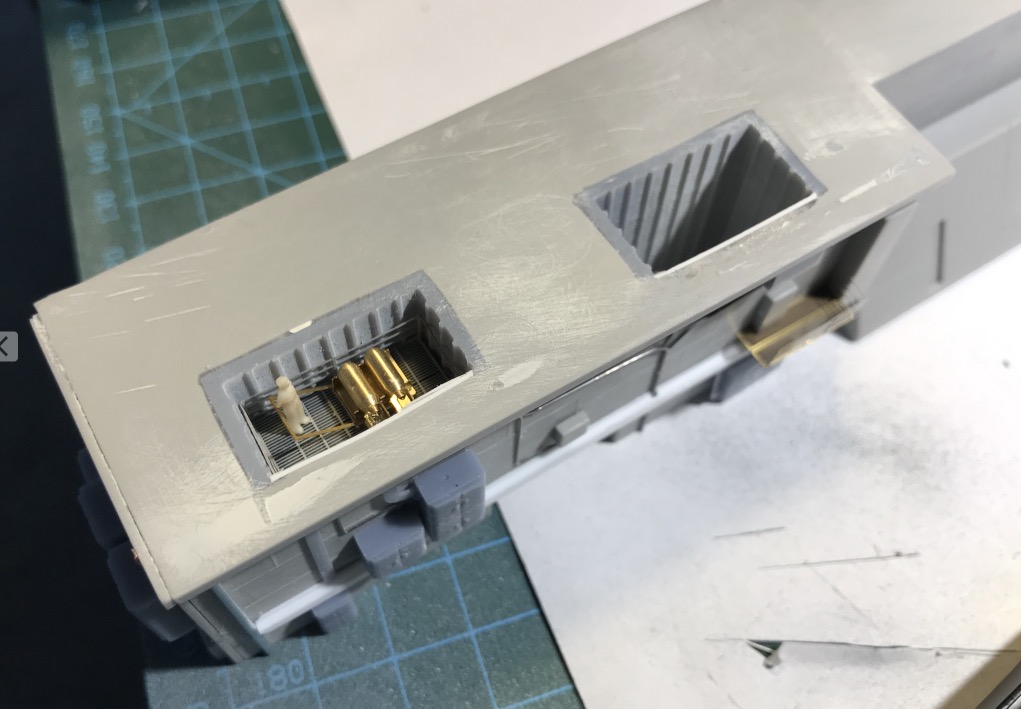
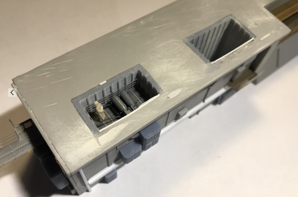
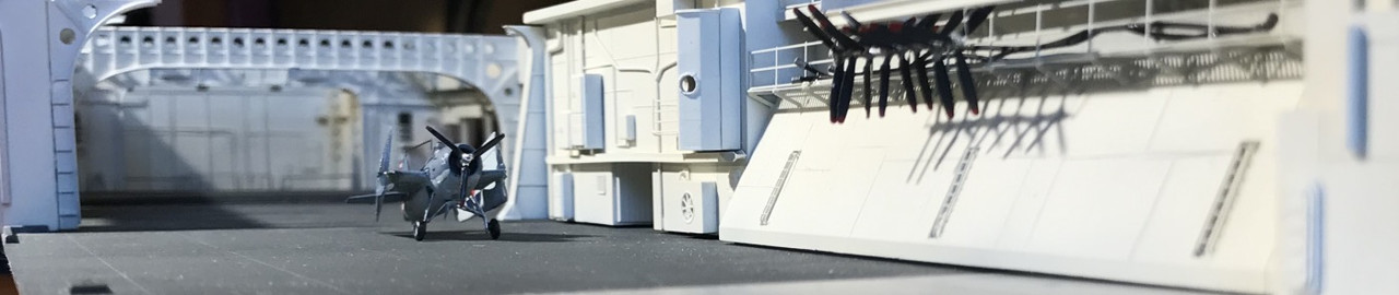
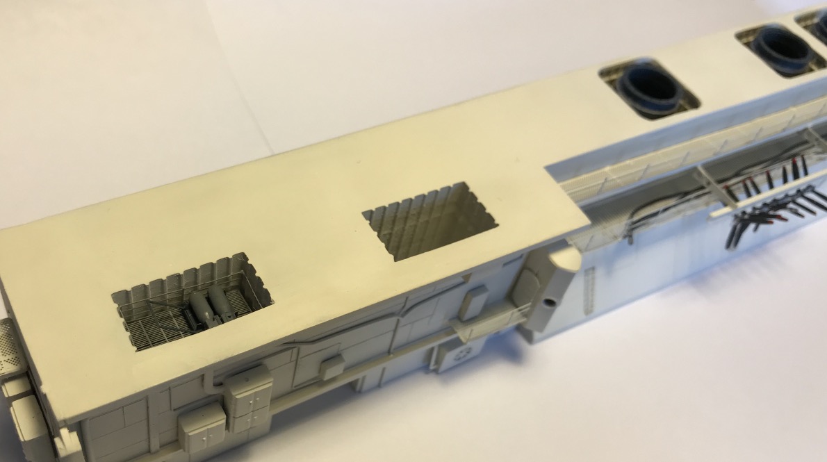
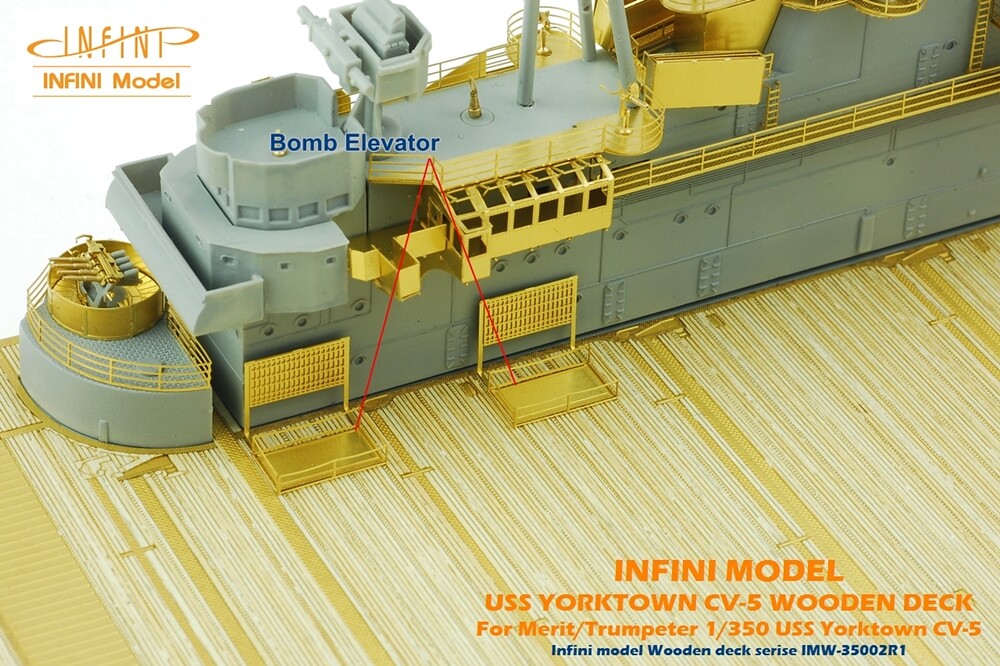
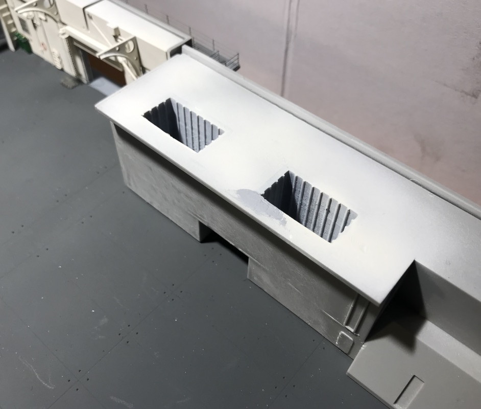
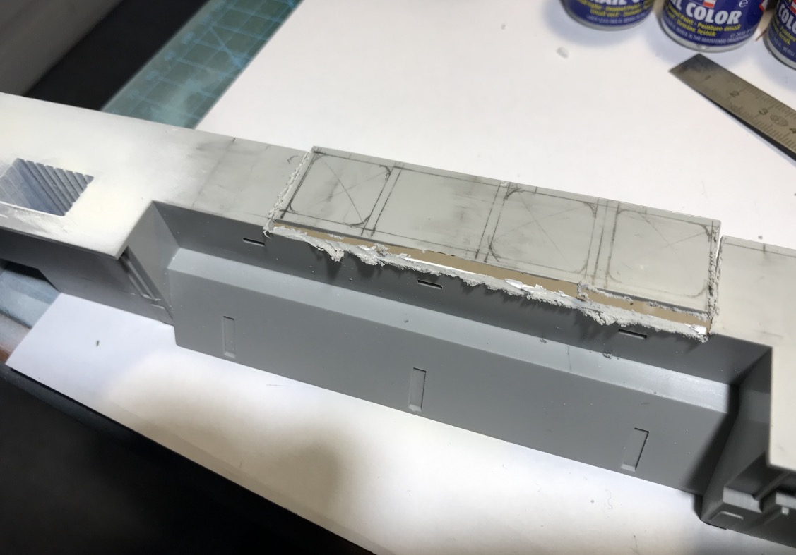
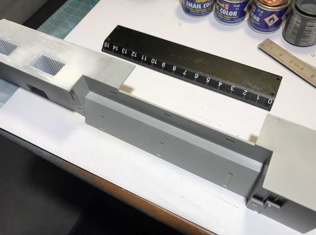
I started to take care of the central block under the island. I've done the shafts for the two bomb elevators. They open up to the front of the island at Portside . Unfortunately their location, which seems correct on the flight deck, does not correspond to their location in the central block, there is a big discrepancy.
I wanted to represent an open hatch on the deck with the arrival of the bombs. That won't be possible. Nothing sticks. and it is too complicated to rectify, at the flight deck level (think of the wooden deck), or at least complicated at the central block level, but not much better. So I don't touch anything.
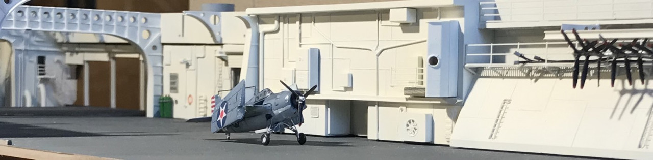
So the scene will look like this after some reflection:
Flight deck, one of the two elevator hatches open, the stage is flush with the bridge loaded with the bomb.
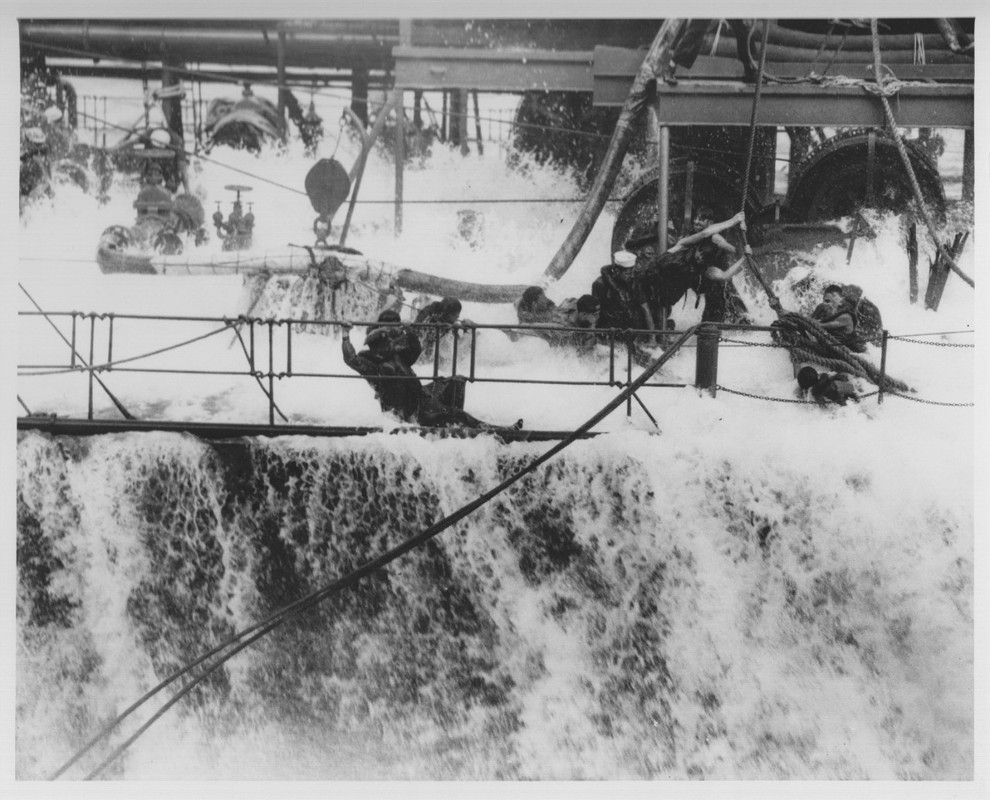
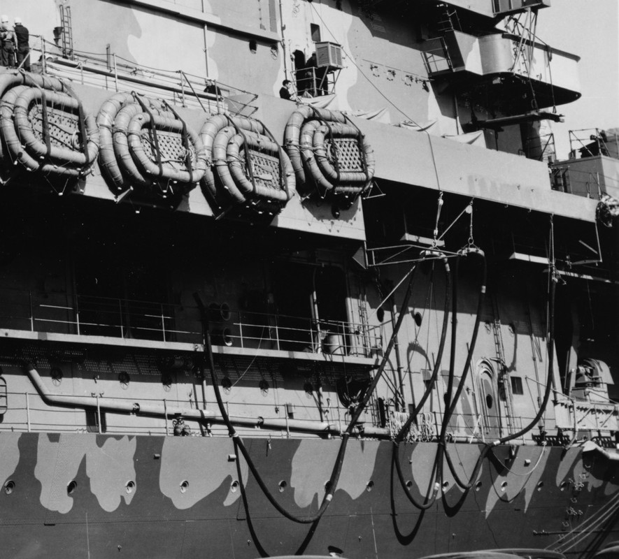
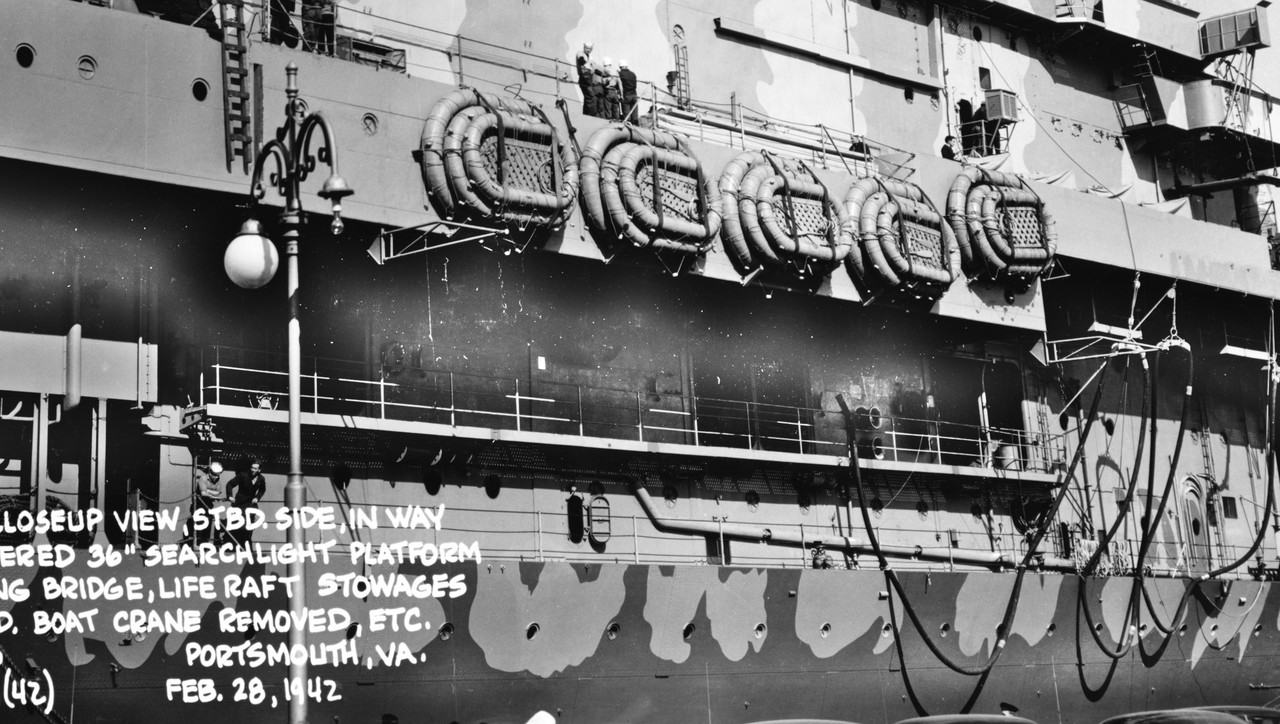
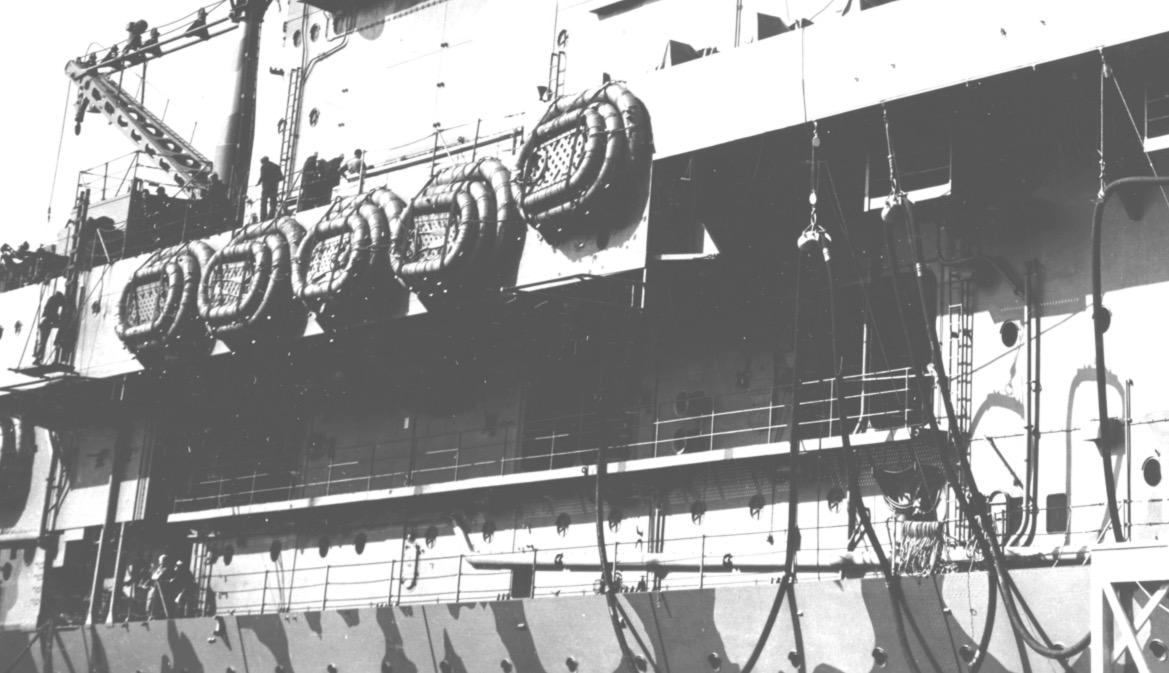
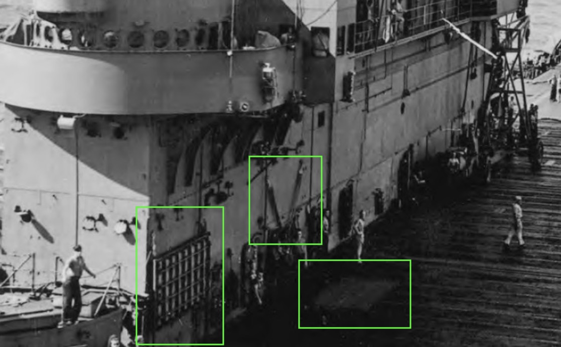
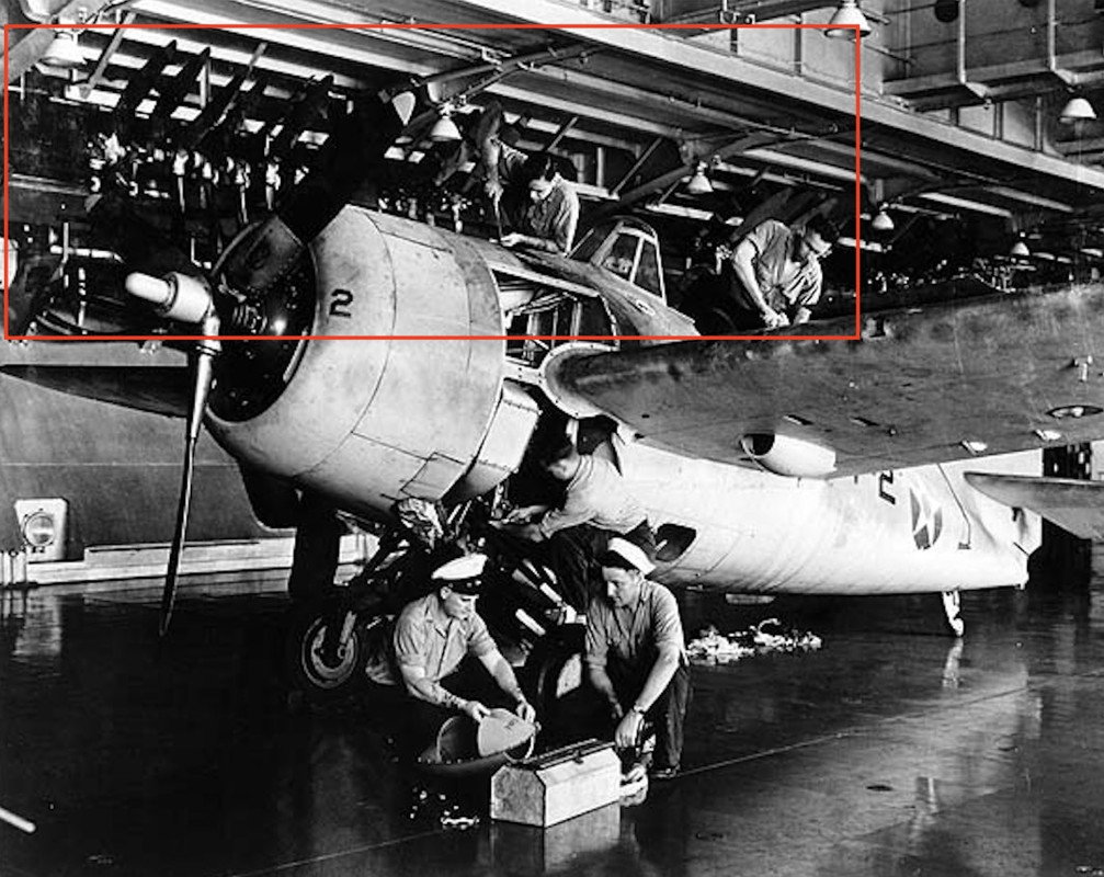
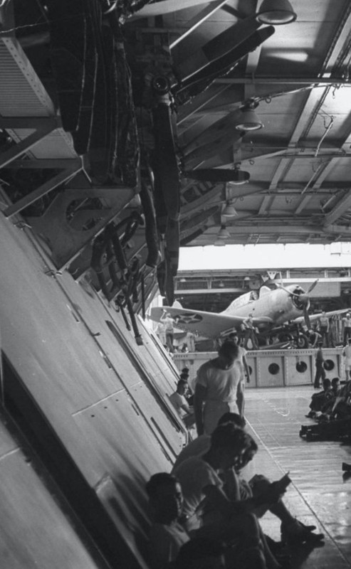
We see on this capture of the film shot on the Hornet, the two elevator hatches. The hatches are opened with foam hoists, it's not hydraulic apparently. I discovered thanks to this film, the usefulness of these two hoists that I had seen on other photos well before.
https://youtu.be/NfmQr9mQMJk
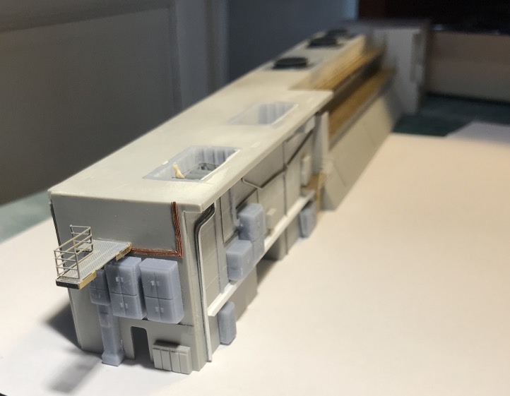
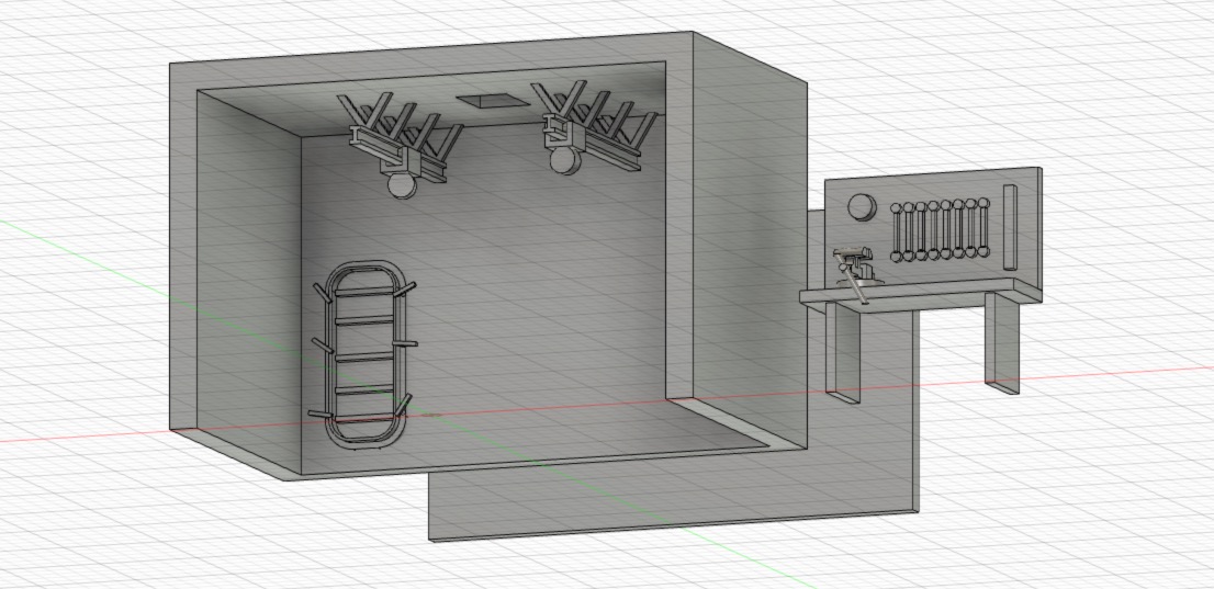
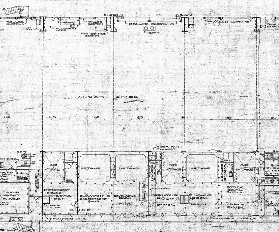
Hangar: When you remove the bridge, you will see one or two elevator platforms at different heights loaded with B-25 bombs.
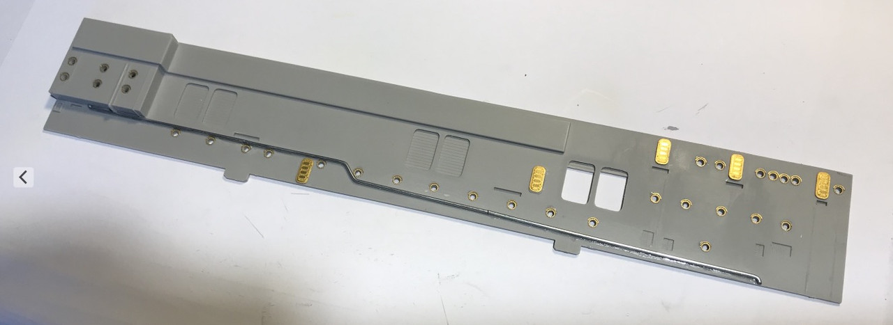
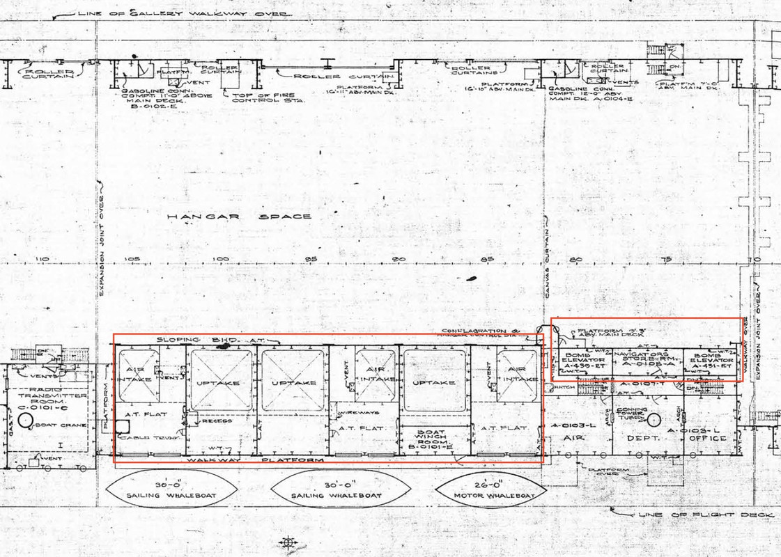
So I designed the two elevator shafts, cut out the flight deck, and the roof of the central block of the hangar to insert the two shafts properly.
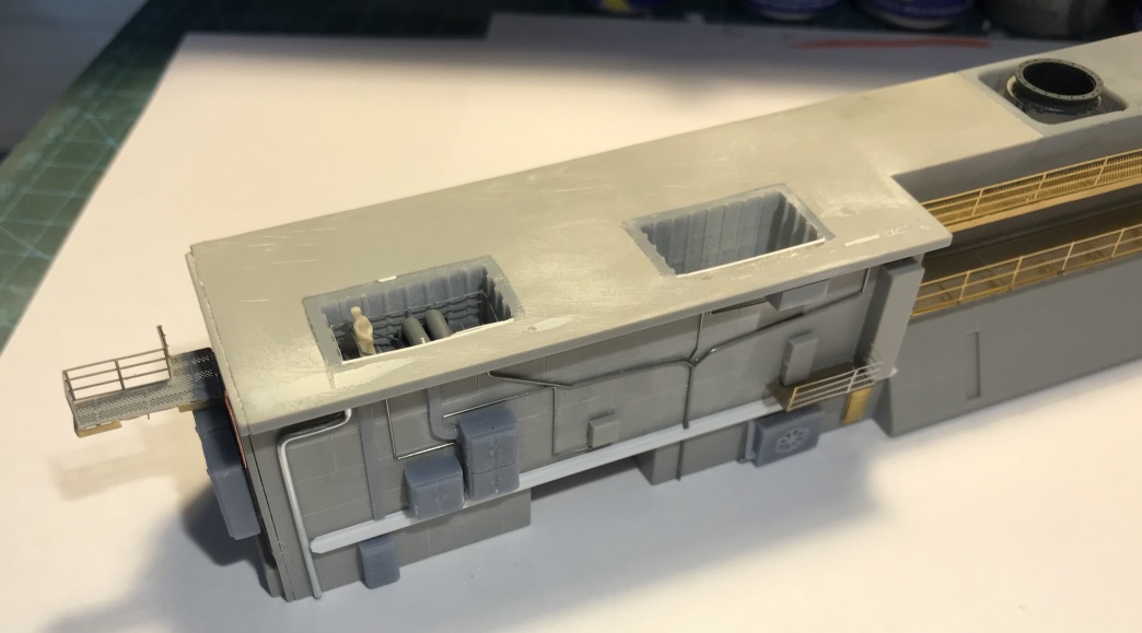
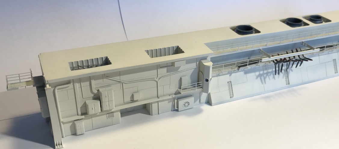
I would have other inserts to make more on the back of the block for the machine ventilation and the chimney pipes that we will be able to see the deck once removed. Beautiful parts in perspective!
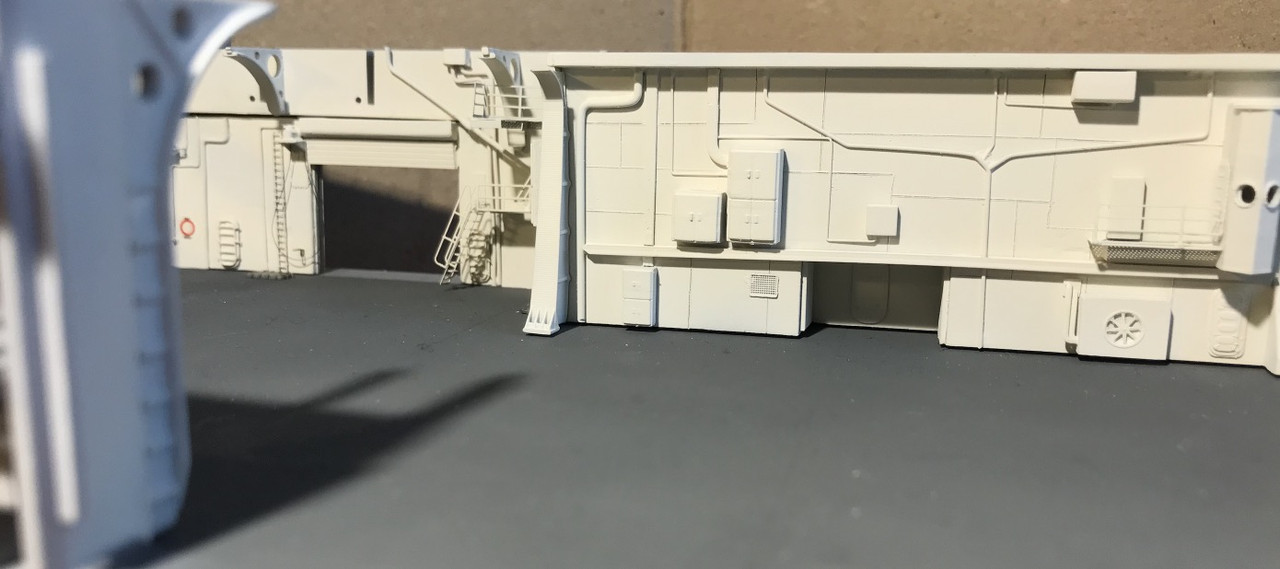
On the central block, I "gummed" on the central partition all the existing reliefs, pipes etc... to place scratch.
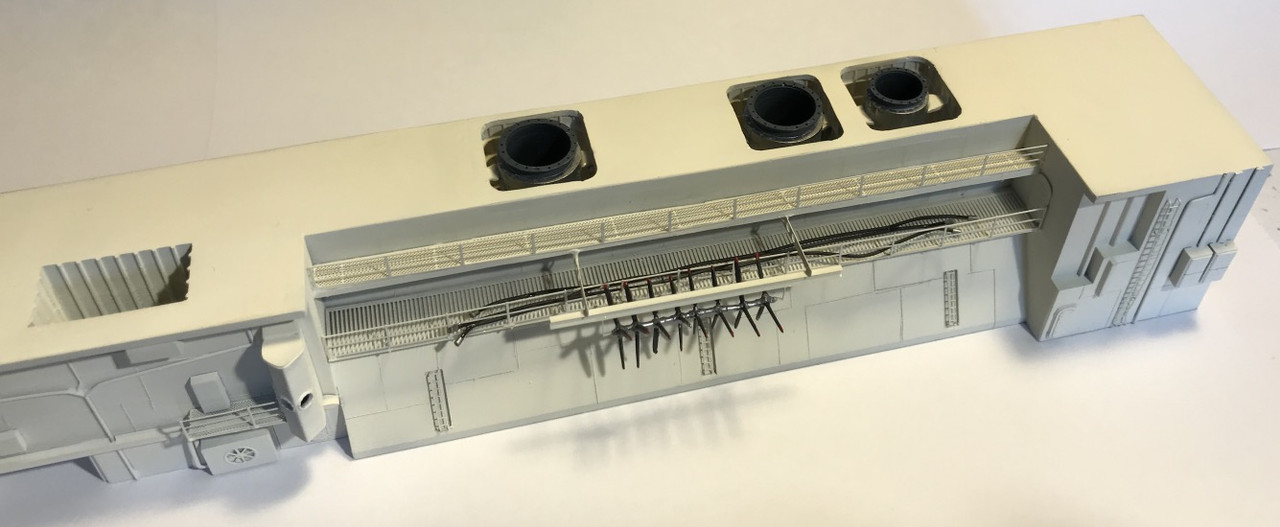
My progression is similar to that of a tunnel boring machine, I dig the tunnel, I lay the concrete plates, the accessories, then the rails...

and so on towards the back.
A little too thick, have to modify also this one.
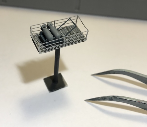
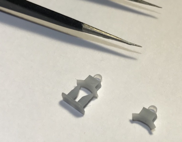
Ammunitions elevator cage:
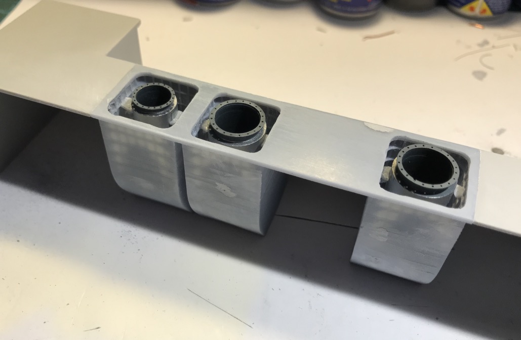
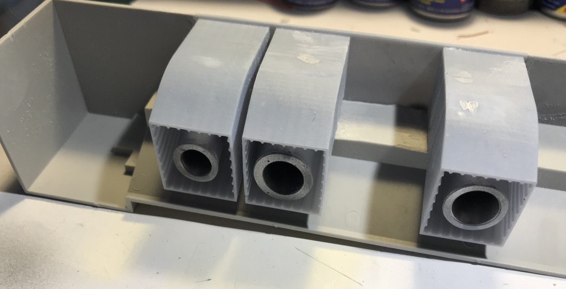
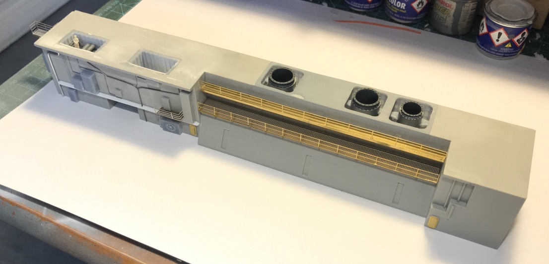
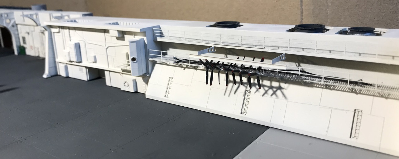
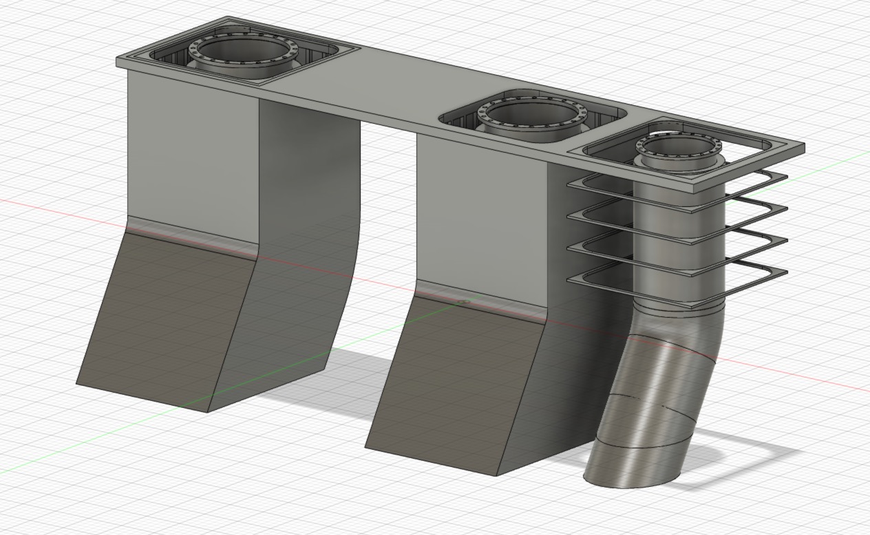
I'm working on the exhaust gas pipes of the nine boilers. There are 3 of lesser capacity on the aft, so the rear exhaust pipe is smaller than the two other.
I don't represent the ventilation casings of the different machine compartments.
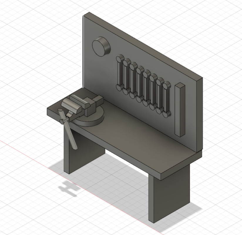
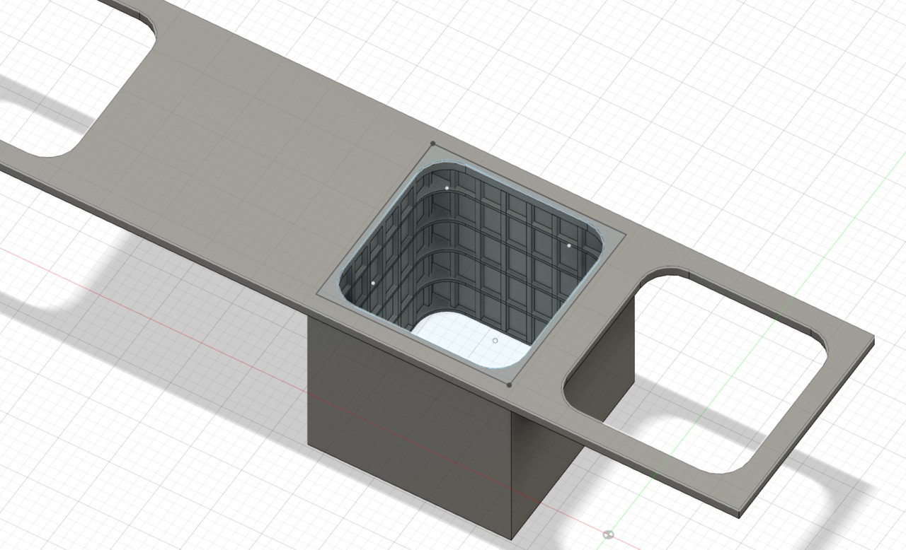
Here is the 3D creation process, step by step, of the different objects that will compose this part of the central block.
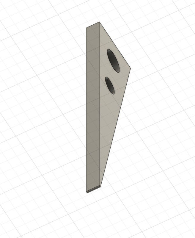
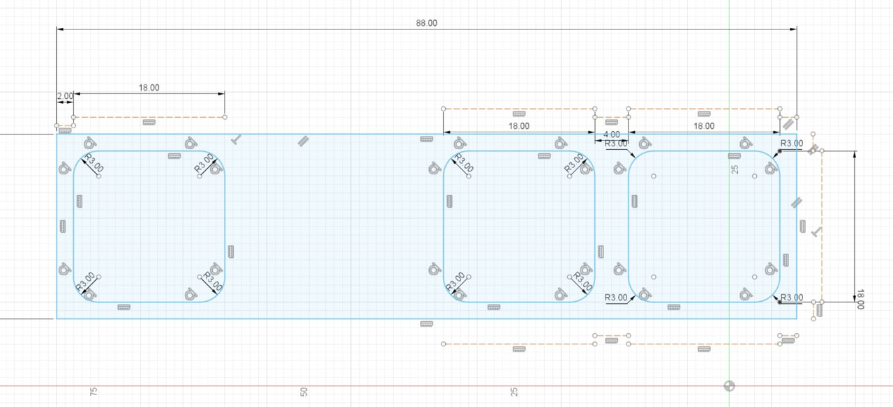
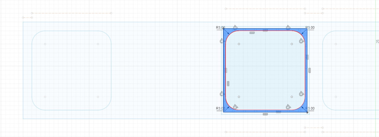
First I make a 2D sketch of the platform that will replace the part I cut out of the block.
It allows me to place the different dimensions of the openings to be created.
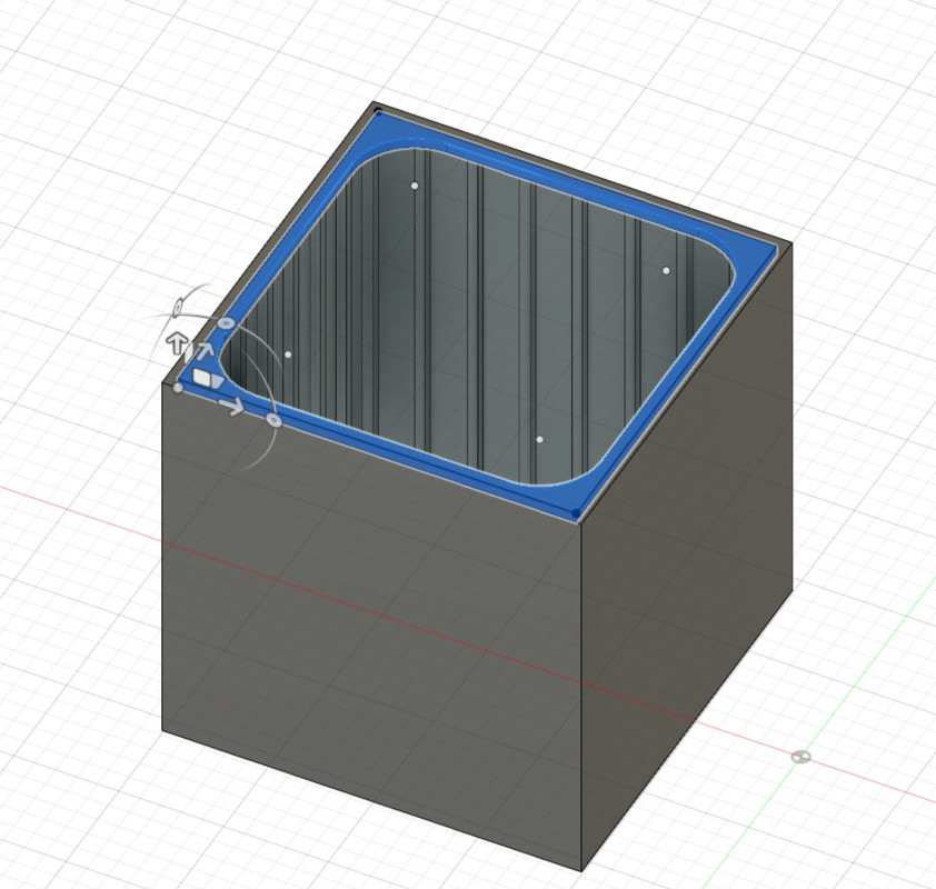
After I extrude this drawing to the thickness of the plastic of the block, I now have a good base to start with.
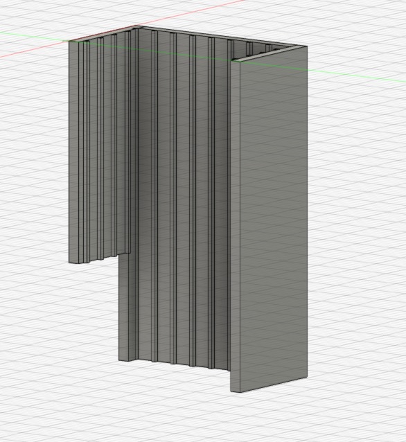
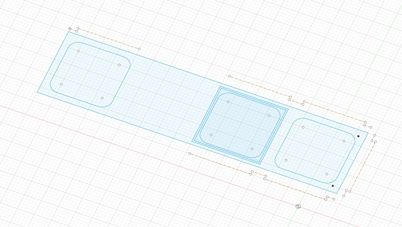
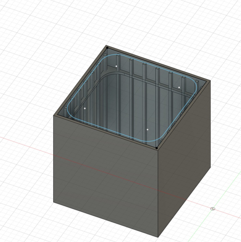
I do the same on the sketch for the partitions of the casing.
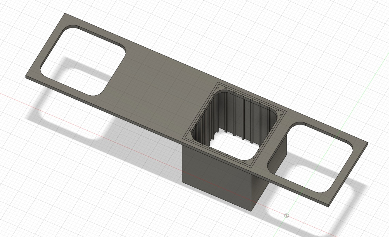
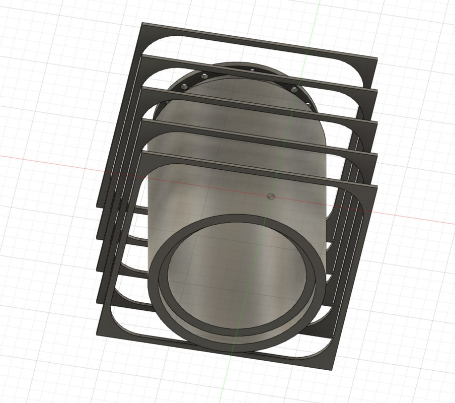
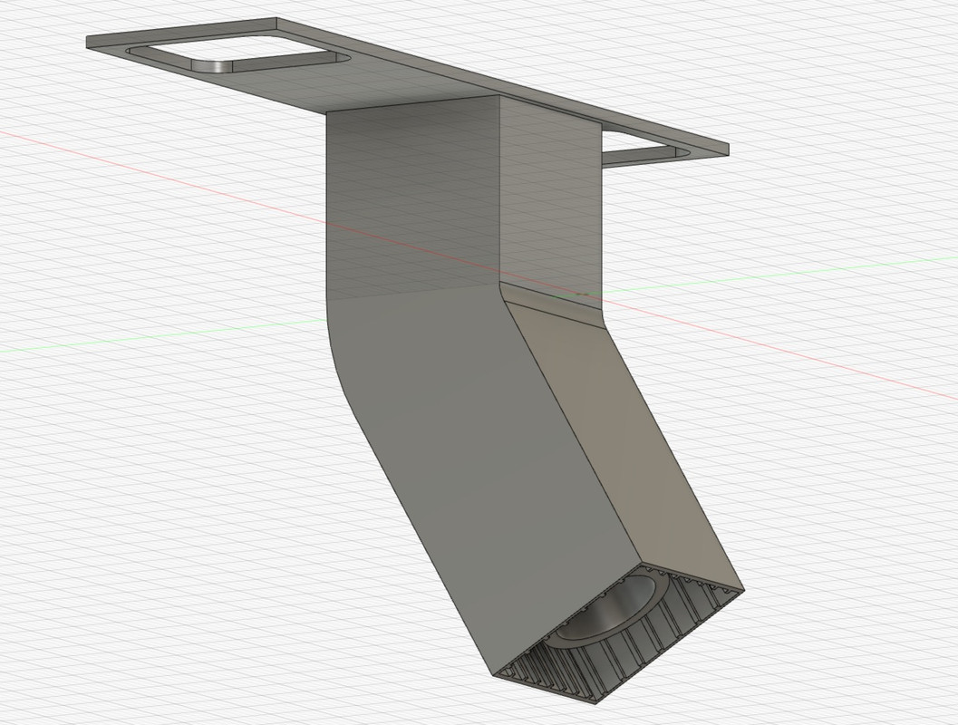
I extrude the 4 walls up to the height of the elbow, as the chimney flue runs at an angle of 60° at one point.So I have to plan the next step...
As the three are identical, I'm focusing on this first one to finish it completely, I'll do a copy/paste later.
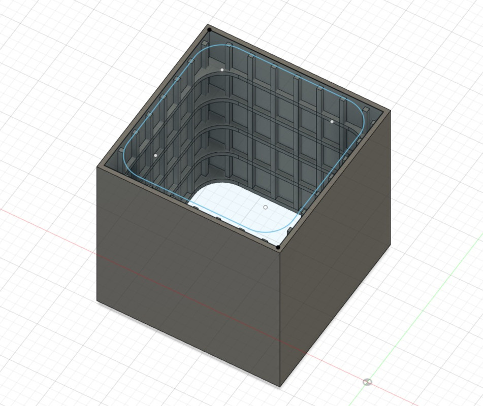
I'm working on the vertical wall stiffeners.
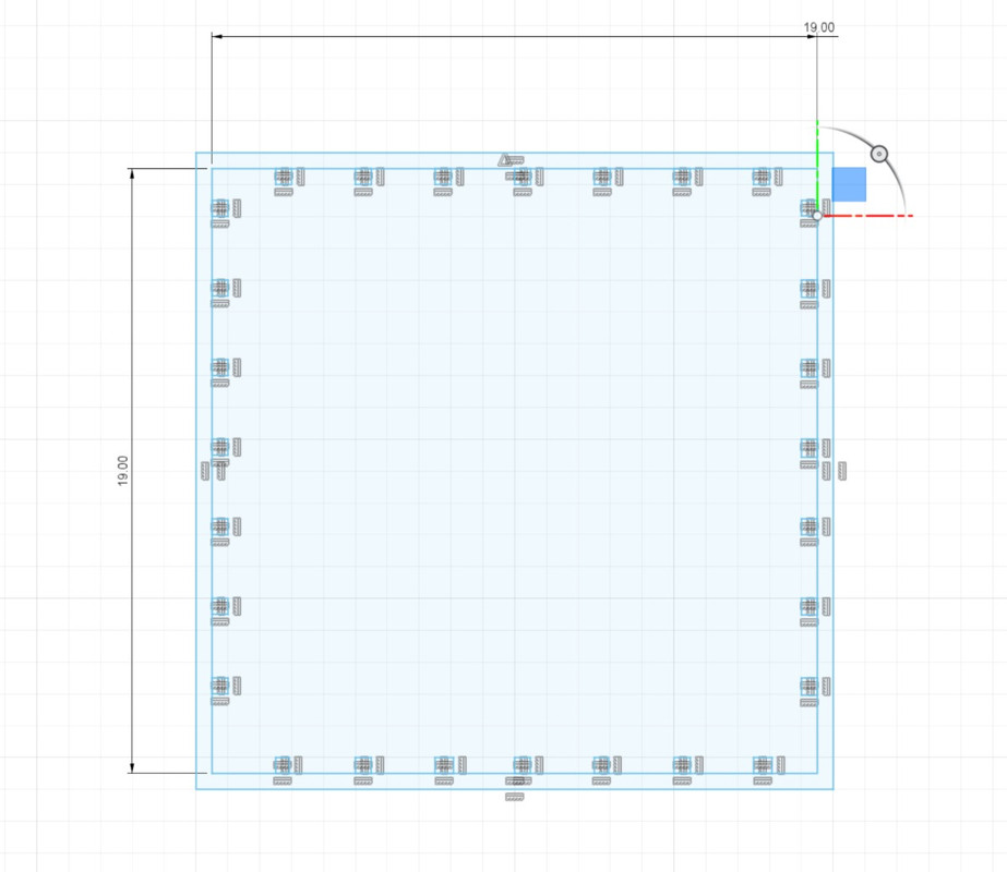
That I extrude too.
Then the horizontals, 5.
Then we do copy and paste, it goes fast.
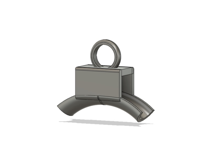
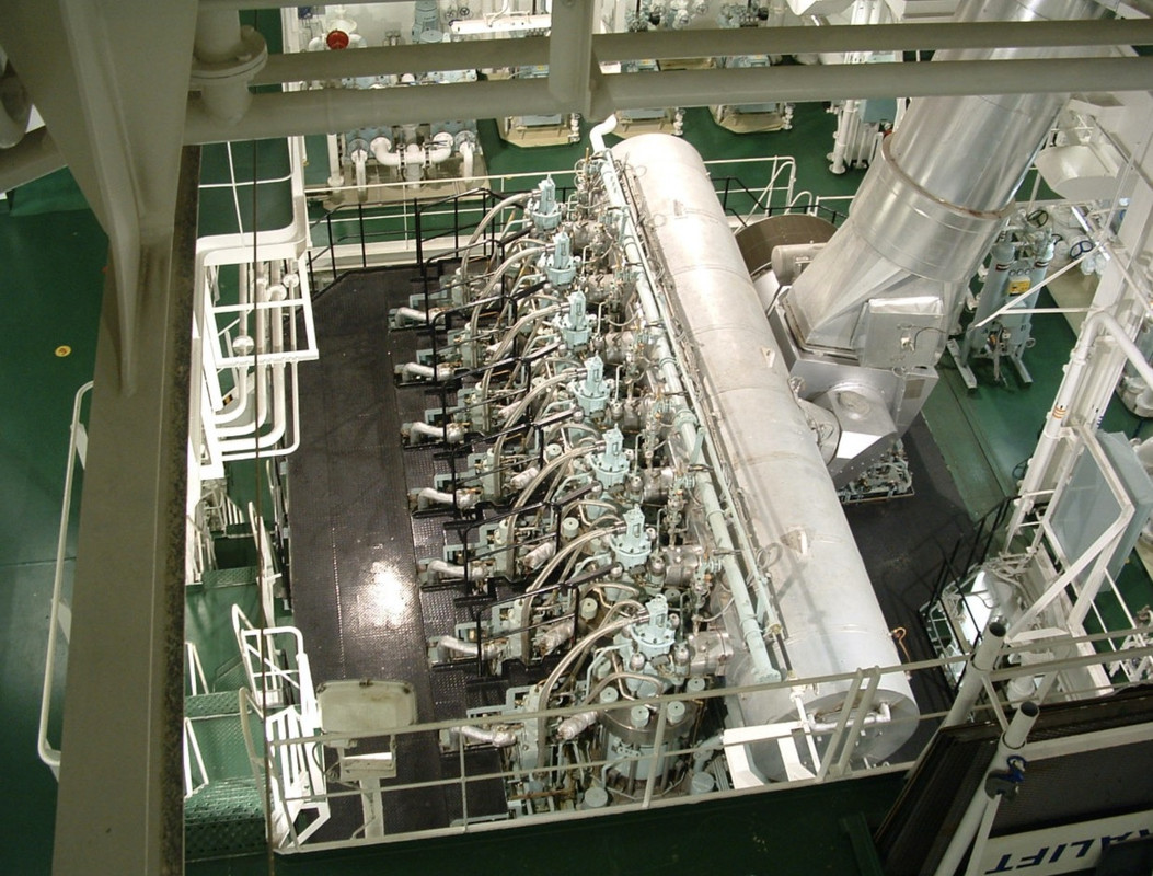
I create the first exhaust pipe, it is surrounded by insulation, probably asbestos at the time, confined with thin sheet metal. It's not done like that anymore of course, nowadays, we mainly use rock wool which resists well to high temperatures.
A bit like here on the exhaust outlet of the single turbocharger of this 14000 HP 2-stroke Burmeister B&W engine, the part with a larger diameter contains the expansion bellows with its mounting flanges. Personal photos.

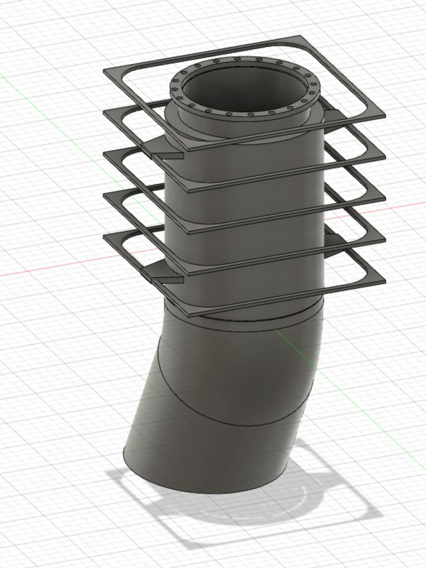
Creation of the pipe, then its flange.
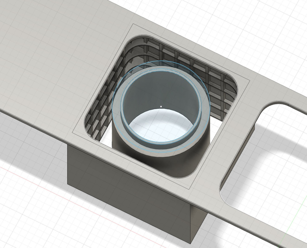
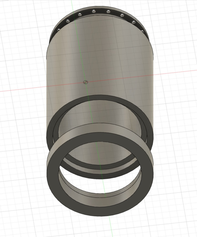
I built the pipe in two pieces that will fit together. Because it has to be easy to mount all this and above all it has to be painted in different colours. You always have to think about painting.
I extrude all this but by bending the shapes along a very precise axis and angle, that of the block.
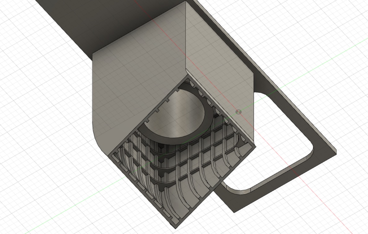
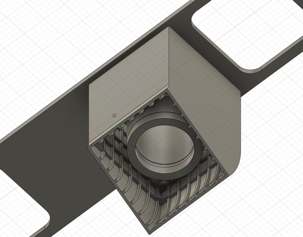
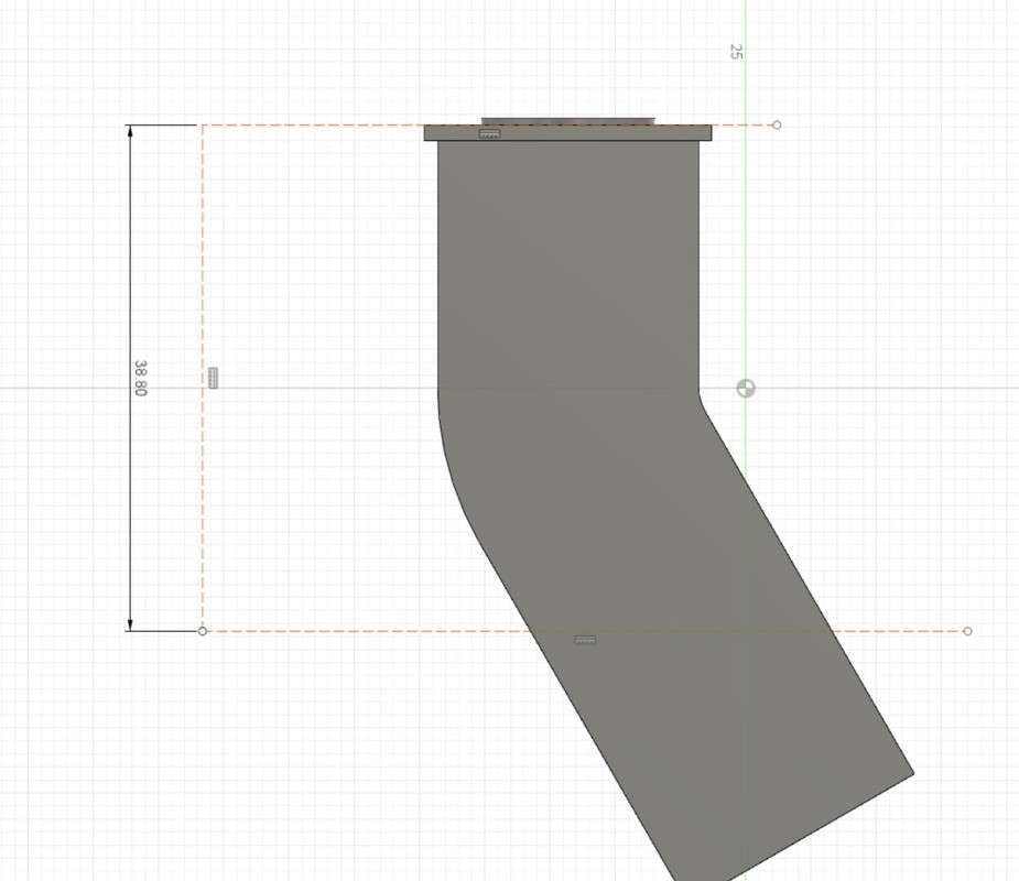
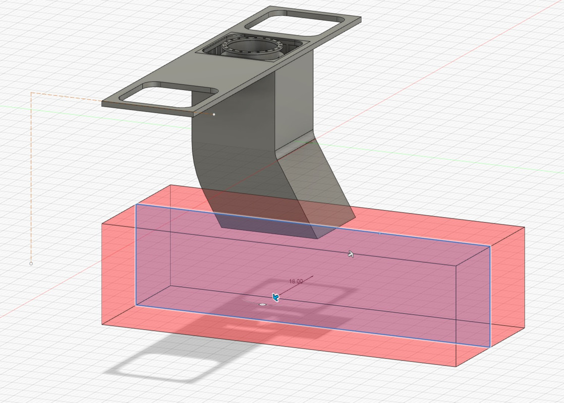
I draw a construction line that will give me the position of the hangar floor thanks to the dimension in relation to the ceiling of the block, that's where I have to cut the casing and the pipe.
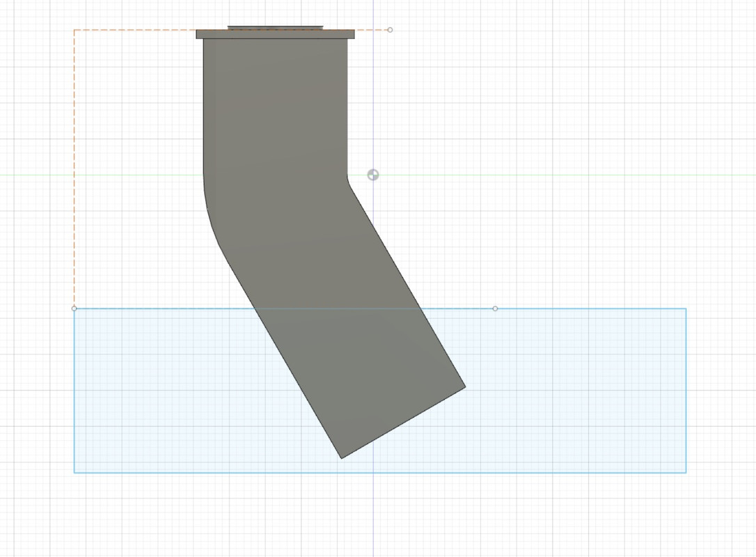
From there, I create a rectangular shape which will be used as a digital cutter, I will extrude this shape but in negative, all that will pass in its field will disappear, hence the red.
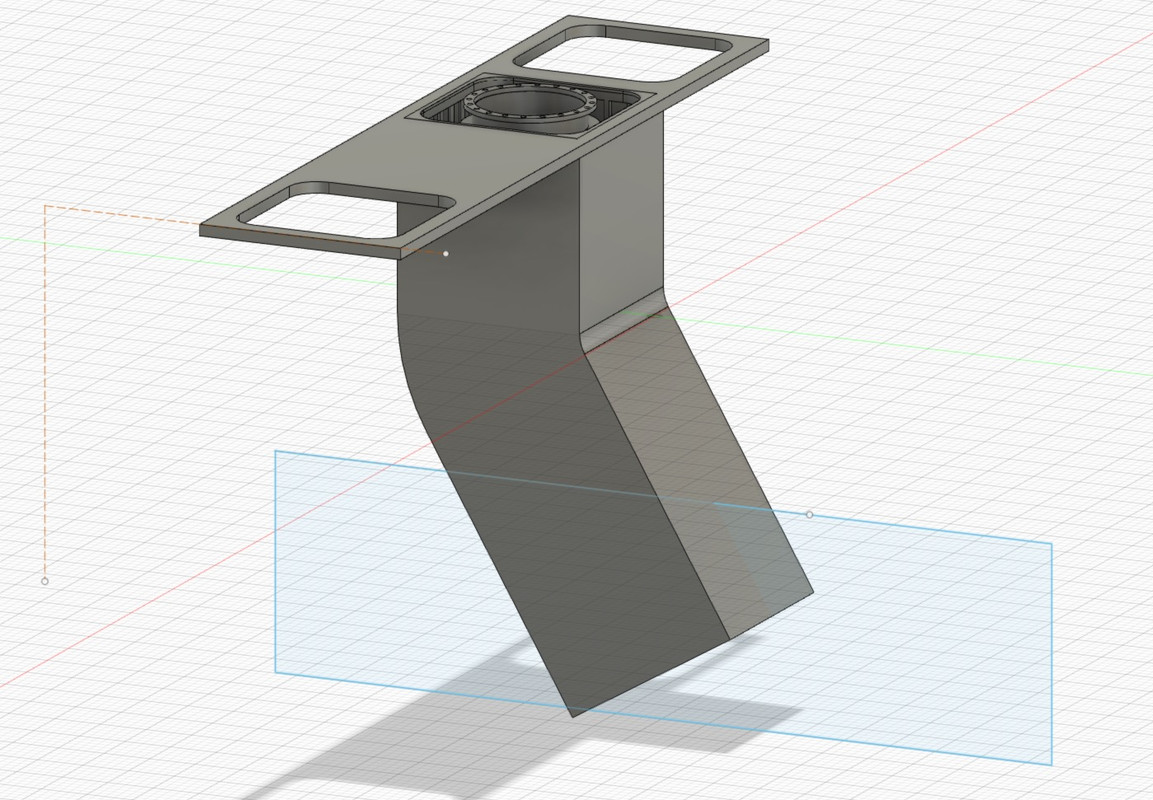
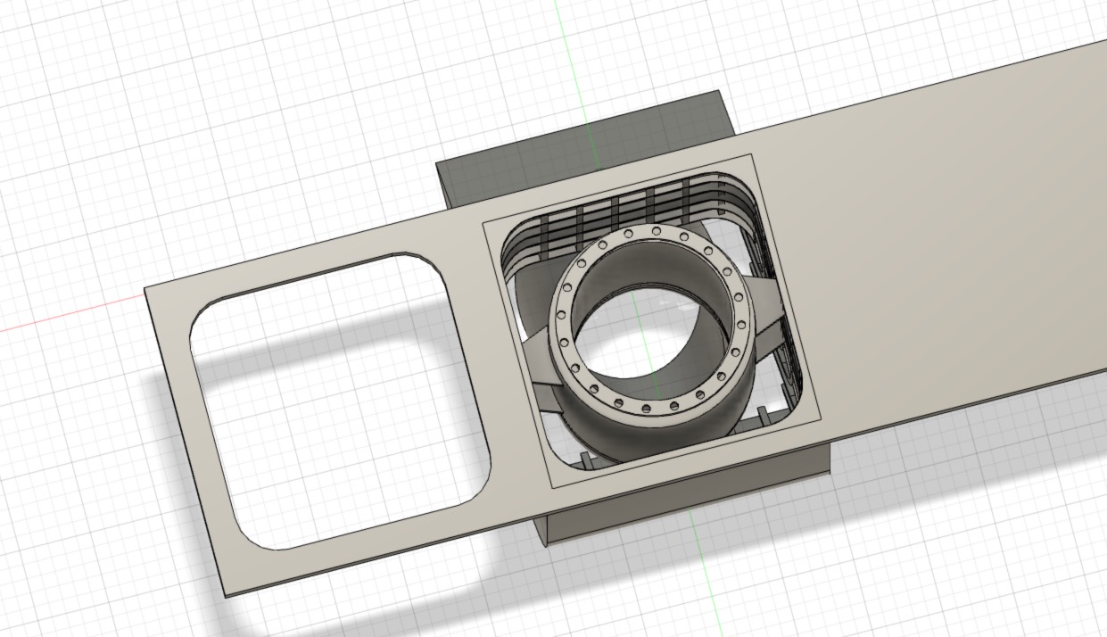
Well, that's almost done for this part. The pipe anchors still have to be installed in relation to the casing.
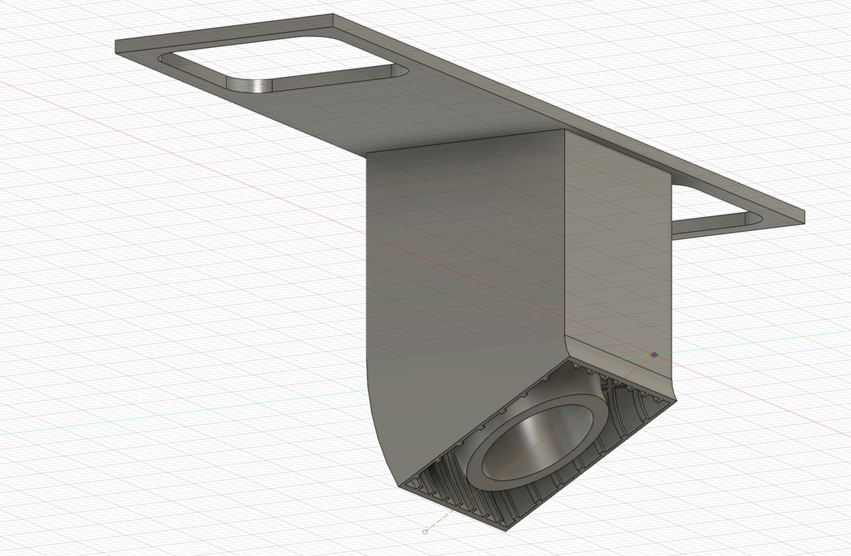
That's it, there's still the smallest pipe left to create and position in place.
I make a copy and put it in the front slot.
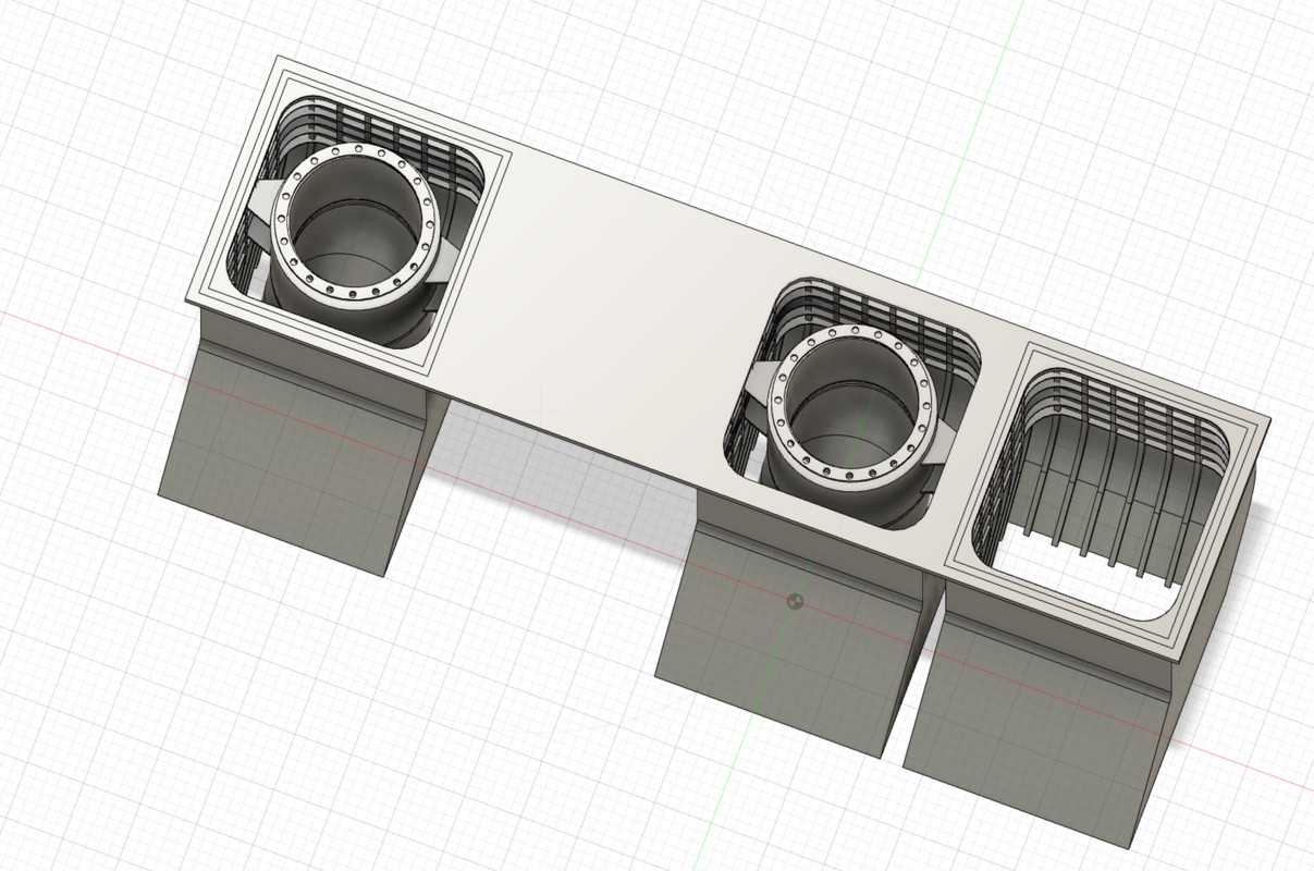
No need to rebuild a pipe, I reduce the size of the big one and adapt the junction with the shed floor.
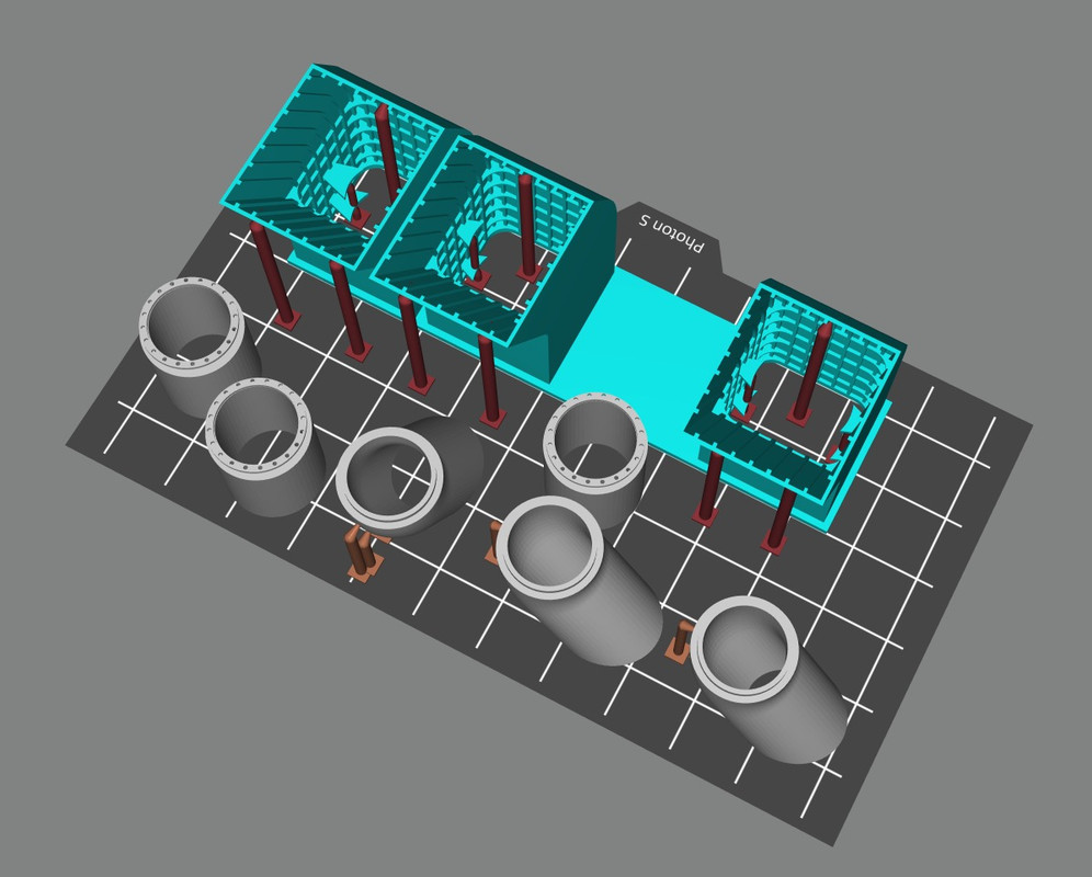
This time the module is complete, all the elements have to be saved in a .STL file in order to print them separately. Because each element will require a specific treatment for printing in terms of support.
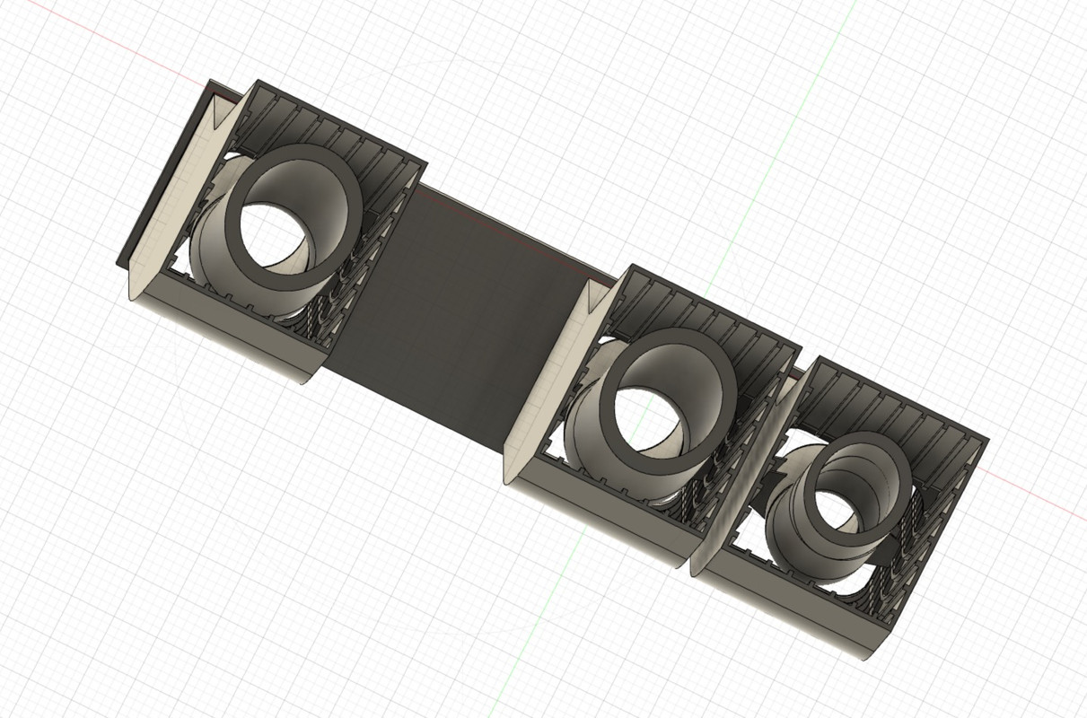
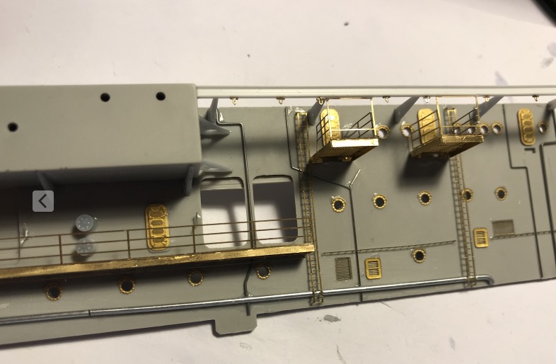
The printing plate is well filled, the reinforcing brackets are in place.
We'll see the result in 3 hours...
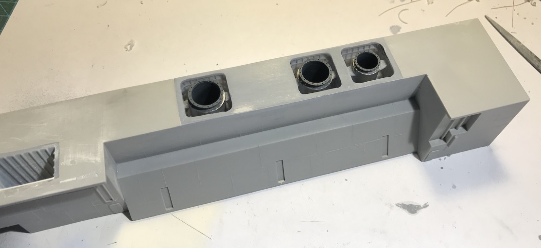
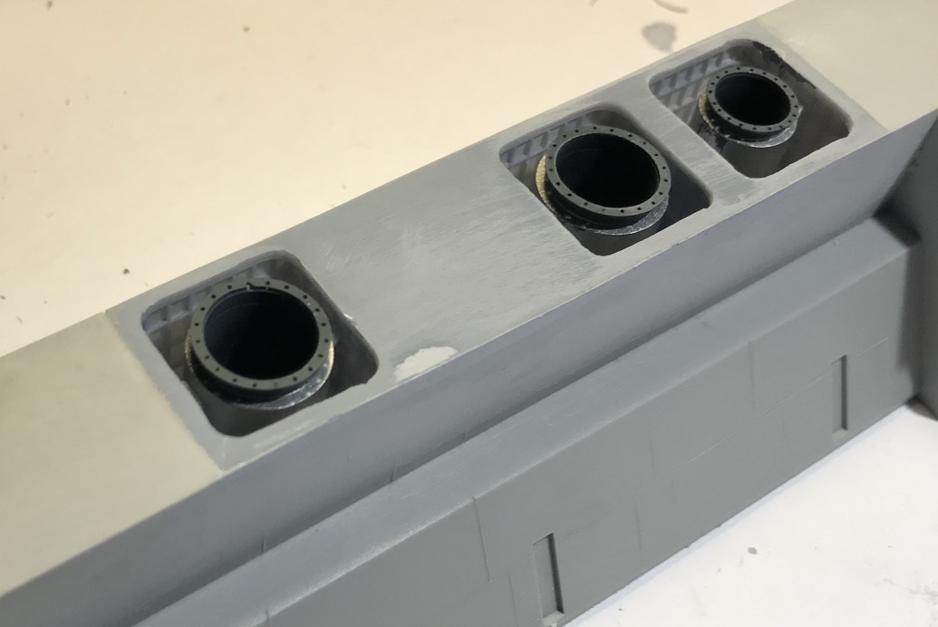
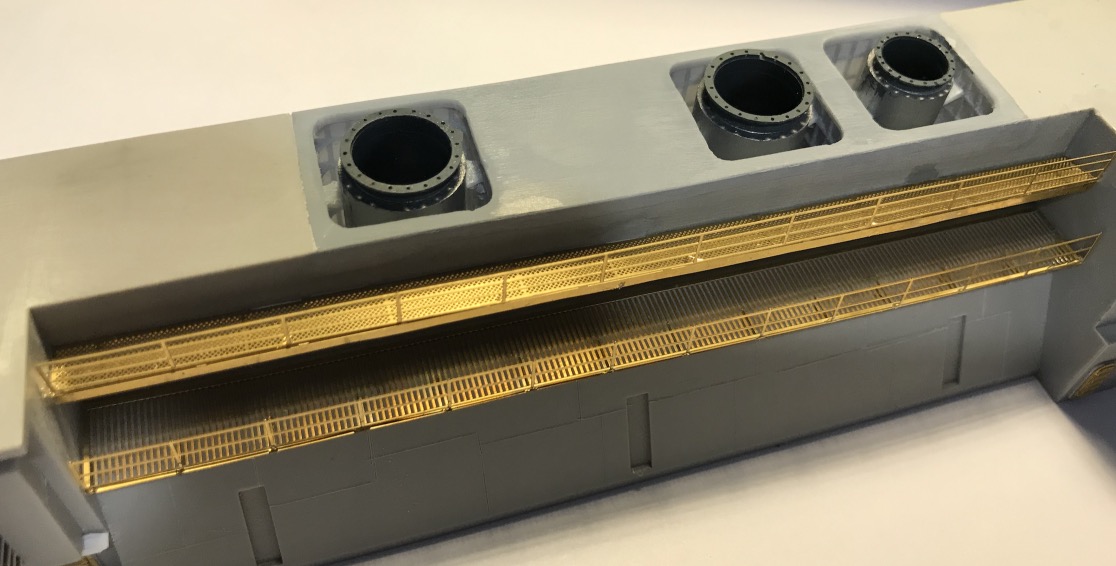
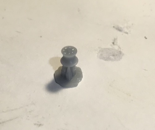
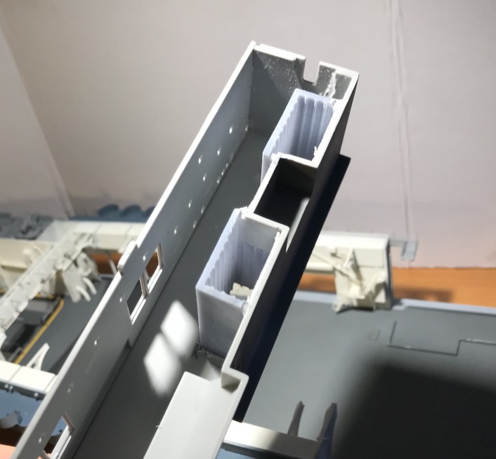
Printing It's not too bad, I had to re-drill the holes a bit because it's very small, with a 0.3 mm drill bit.
There is still the white paint to apply inside the ducts, white slightly yellowed compared to the white of the garage because of the heat.
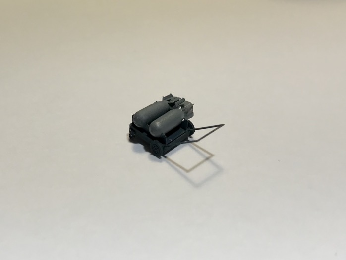
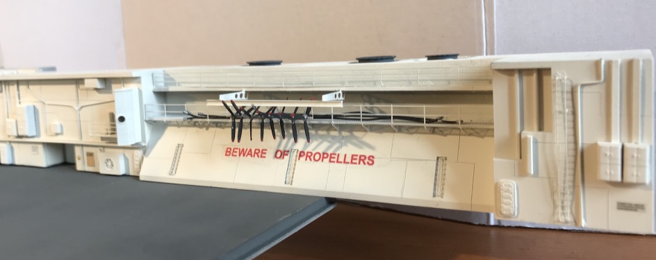
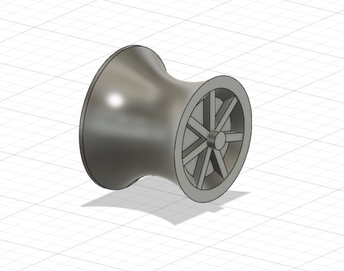
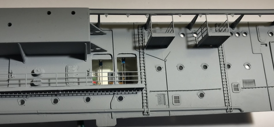
I continued to furnish the central block, including the bomb and torpedo lift. There is the spare propeller rack to be created as well.
A good part of this block and the details I have added will not show because there is a garage ceiling accommodation on this level, they will be represented, cabins, offices, pilots briefing room, Admiral's cabin, Master's cabin etc..