The Ship Model Forum

The Ship Modelers Source
It is currently Sun Apr 28, 2024 8:50 am

All times are UTC - 6 hours [ DST ]


Post new topic Reply to topic  [ 31 posts ]  Go to page Previous  1, 2
Author Message
PostPosted: Tue Oct 17, 2023 7:43 pm 
Offline
User avatar

Joined: Mon Nov 18, 2013 3:41 pm
Posts: 2954
Location: Mocksville, NC
B2010,

Your final product looks very good. Getting to that point, was obviously a bit of a hard road. I can fully understand - been there, done that. Once again - you're working on a 5" gun MOUNT, not turret!!!

As I'm into the 3D design/printing, etc. I will comment on something that may help you out - when I got my new printer earlier this year, I was experimenting with other resins as I think I mentioned a while back. I was also at that time starting the layout of supports and using a raft. I found that it was not only unnecessary but taking up height space not to mention resin use. If I were you, I would turn off the raft feature and go back to individual supports with their own base. The thing to make sure of is that the bases all join, and it will then form a raftlike base without the extra height and resin usage. In doing so, I would also increase the supports to perhaps Medium and then adjust the diameters accordingly.

I'm also experiencing a bit of resin curing inconsistency in my large-scale director prints and will use your comments regarding the exposure time as a reference. I did slightly increase the E.T. last week, but will make a larger adjustment for my next round of prints.

As for your HVAC ductwork, if you had any drawings showing this ventilation system, they should have had the duct sizes on them. Plan view drawings would show them with width x height. Elevation drawing show the height x width.

Hope this helps,

_________________
HMS III
Mocksville, NC
BB62 vet 68-69

Builder's yard:
USS STODDARD (DD-566) 66-68 1:144, Various Lg Scale FC Directors
Finished:
USS NEW JERSEY (BB-62) 67-69 1:200
USN Sloop/Ship PEACOCK (1813) 1:48
ROYAL CAROLINE (1748) 1:47
AVS (1768) 1:48


Report this post
Top
 Profile  
Reply with quote  
PostPosted: Fri Oct 20, 2023 5:29 pm 
Offline
User avatar

Joined: Tue Feb 22, 2011 7:45 pm
Posts: 139
Work progresses...

I designed the Training Gear hydraulic plant. This sits down between the girders on the gun house's right side behind the Trainer's seat and regulator. Luckily this one is drawn in profile in one of the cross-section images I found so I could get the profiles down. I've scaled these drawings so they are representing correct lateral dimensions.

There are two output shafts that extend out of the end and I probably will make these out of correctly sized wire. It was gratified after finishing the drawing that it fit perfectly in the space it was supposed to. I have an add-on that facilitates making those neat curved edges. Also, SU is pretty easy to draw complicated pipe runs once you know what you're doing with connecting lines and adding curves to them.

Attachment:
Training Pump.png
Training Pump.png [ 466.86 KiB | Viewed 588 times ]


Here it is dropped into position.

Attachment:
5IP Gun House w Training Pump.png
5IP Gun House w Training Pump.png [ 670.07 KiB | Viewed 588 times ]


Next up will be to design this units hydraulic counterpart, the Elevation Gear Hydraulic Plant.

As in the big gun's turret, all the systems are driven by hydraulic motors with the pressure generated in a remote motor/pump setup. In the case of the big gun, the motor/pump (A-end) was physically remote from the hydraulic motor (B-end), but in the case of this smaller turret complex, the motor/pump was directly in line with it's b-end hydraulic motor.

With my newly refined printer setup, I have no doubt that all that delicate piping will render. It should look pretty good.


Report this post
Top
 Profile  
Reply with quote  
PostPosted: Sun Oct 22, 2023 2:12 pm 
Offline

Joined: Wed Jan 02, 2013 1:15 am
Posts: 5012
At that scale the piping should print well, these are similar piping wise to smoke generators I have printed before. Good research finding out about this ancillary equipment, often hard to work all of this stuff out.

Cheers: Tom


Report this post
Top
 Profile  
Reply with quote  
PostPosted: Sun Oct 22, 2023 6:06 pm 
Offline
User avatar

Joined: Tue Feb 22, 2011 7:45 pm
Posts: 139
I also finished the elevation hydraulic system. Both are now printed and with my new settings ALL of the piping reproduced perfectly AND it's much stronger to handling that it was with my previous under-exposed setting.

The motor, reservoir and gear box was the same for the Training Hydraulics as the Elevation Hydraulics, but the output side was different. Furthermore, they're mirror images of each other. I'm now working on the human interface portion of these systems. They difficult to draw because they have lots of angles and curved/blended edges, neither of which is something SU is particularly good at.

Attachment:
5IP Elev Pump Comp 1.png
5IP Elev Pump Comp 1.png [ 578.85 KiB | Viewed 550 times ]


Attachment:
5IP Elev Pump Comp 2.png
5IP Elev Pump Comp 2.png [ 995.78 KiB | Viewed 550 times ]


Attachment:
5IP Elev Pump in Place.png
5IP Elev Pump in Place.png [ 1 MiB | Viewed 550 times ]


Report this post
Top
 Profile  
Reply with quote  
PostPosted: Tue Oct 24, 2023 6:07 pm 
Offline
User avatar

Joined: Tue Feb 22, 2011 7:45 pm
Posts: 139
Back to the ship.

My first prints of the elevation and training pump systems was okay, but a couple of details didn't form and it bugged me. Here's the first attempt.

Attachment:
5IP Turret Pumps First run.jpg
5IP Turret Pumps First run.jpg [ 1.9 MiB | Viewed 532 times ]


You probably can't find the errors, but I know they were there. I tried them on to see how they looked sitting in the framing. And they looked swell.

Attachment:
5IP Elev Pump Test Fit.jpg
5IP Elev Pump Test Fit.jpg [ 1.6 MiB | Viewed 532 times ]


Attachment:
5IP Training Pump Test Fit.jpg
5IP Training Pump Test Fit.jpg [ 2.45 MiB | Viewed 532 times ]


When I went back and evaluated the support scheme, I found that I misplaced the tiny support on the upper side of the detail, not the bottom-facing apex. This caused the detail to not form correctly until the build reached where the support was. This is support skills 101: the support goes at the bottom-most point what would start to form and create an island. There's a moving line in the slicer that helps you identify this contact point. In this case, I missed it a bit.

When I repositioned the errant supports I got a really nice print. I also moved some supports or made them smaller where they were difficult to remove without damaging the model.

Attachment:
5IP Pump Run 2 Motor End.jpg
5IP Pump Run 2 Motor End.jpg [ 1.03 MiB | Viewed 532 times ]


Attachment:
5IP Pump Run 2.jpg
5IP Pump Run 2.jpg [ 1.37 MiB | Viewed 532 times ]


Those piping details are very, very fine. The phos-bronze wire is showing where the links are going to connect to the regulating pedestal. They will not be this long. I pre-"drilled" the holes in the drawing so I could easily open them up with a 0.032" drill.

The new setting is amazing. It's like learning to 3D print all over again. I'm also reprinting the foot rungs since the new setting will make a truer and stronger part, plus a less warped base that I'm using as a drill jig.


Report this post
Top
 Profile  
Reply with quote  
PostPosted: Wed Oct 25, 2023 12:45 pm 
Offline

Joined: Wed Jan 02, 2013 1:15 am
Posts: 5012
Good work and glad that you have been able to tune in your printer settings as well as your supports. It's not a push button system and requires much experimentation and experience!


Report this post
Top
 Profile  
Reply with quote  
PostPosted: Sun Oct 29, 2023 4:08 pm 
Offline
User avatar

Joined: Tue Feb 22, 2011 7:45 pm
Posts: 139
Work continues on designing the very complex (for me) Elevation Station. This assembly includes all the input controls, the output shafts, the optical telescope and its linkage, the elevation gear housing and the connecting shafts to the other gun and Sight Setters station. There are no right angles! Making it more complex is the coupling casting that ties the elevating regulator column to the gear housing. This thing. This, BTW, was not correct as drawn here.

Attachment:
5IP Gear Bracket.png
5IP Gear Bracket.png [ 552.36 KiB | Viewed 473 times ]


The reason for all this confusion for me was none of my referece drawings showed the entire part, nor were there any that gave me a true understanding of its geometry. It took well over an hour to get this far. I even sent out the word for help from some other SketchUp, but didn't get a response. Here's what I had to go on.

Attachment:
5IP Gear Bracket 2.png
5IP Gear Bracket 2.png [ 842.26 KiB | Viewed 473 times ]


Attachment:
5IP Gear Bracket 3.png
5IP Gear Bracket 3.png [ 908.27 KiB | Viewed 473 times ]


Attachment:
5IP Gear Bracket 1.png
5IP Gear Bracket 1.png [ 1.25 MiB | Viewed 473 times ]


I persisted and eventually landed on a shape that works and looks credible. Whether it's actually correct is a totally different question.

I then took this assembly with the beginnings of the gear housing and put it into position in the gun house on the master drawing. This is what I found.

Attachment:
5IP Elev Gear Fit Challenge.png
5IP Elev Gear Fit Challenge.png [ 354.13 KiB | Viewed 473 times ]


The gear house (and associated shafting) was too low. I also found from a verticle perspective drawing of the turret interior, that the shafting an its associated apparatus were to far left. This is all the result of not having a single orthographic diagram of the equipment design or location. Some are perspective and others are isometric, but locating accuracy was very difficult to achieve. It just a series of aproximations.

I'm satisfied that I've got it right... enough... for now.

Attachment:
5IP Elev Gear Align Rev VIew.png
5IP Elev Gear Align Rev VIew.png [ 619.44 KiB | Viewed 473 times ]


Attachment:
5IP Elev Gear Aligned.png
5IP Elev Gear Aligned.png [ 858.04 KiB | Viewed 473 times ]


The Trainer's station is similar in design to this one and I'm going to use the same "casting" to join it to the other gun's elevating housing. There is another ambiguous part that I need to design. It sits on the gun side of the housing near the bottom and contains a ton of complexity of which I can make no sense. Problem is when I enlarge the drawings to bring out of the detials they disappear since the images were screen prints of scans of a manual and have no resolution when magnified. Again, it will be mostly quess work. I do have a picture of the Trainer's station with this component that shows more detail. I can cannabalize off that one.


Report this post
Top
 Profile  
Reply with quote  
PostPosted: Fri Nov 03, 2023 8:17 am 
Offline
User avatar

Joined: Tue Feb 22, 2011 7:45 pm
Posts: 139
Just a quick progress report. I've spent over a week working on the elevating mechanism and still not done. Nothing about this one is easy to understand or easy to draw. What makes matters worse is the real ship, most of this stuff is buried in the front of the turret up against the lower portions of the armored front and you couldn't get near it to make any real world measurements. I draw it in a separate file, at 100x full size. I then copy it, reduce it to 1:1 scale and export it to the master file. I then fit it to the gun stands and the shell sides. Nothing on the part is a right angles to the SU main axes. I have to figure where the parts need be separated for effective printing.

Attachment:
5IP ELEV WIP.png
5IP ELEV WIP.png [ 389.31 KiB | Viewed 442 times ]


Attachment:
5IP ELEV WIP 2.png
5IP ELEV WIP 2.png [ 246.48 KiB | Viewed 442 times ]


This is a view from the rear which is kind of what you'd see if you actually went into the turret.

Attachment:
5IP ELEV WIP REAR VIEW.png
5IP ELEV WIP REAR VIEW.png [ 244.52 KiB | Viewed 442 times ]


All of this is created with images like this:

Attachment:
Sight Telescopes.png
Sight Telescopes.png [ 1.04 MiB | Viewed 442 times ]


Report this post
Top
 Profile  
Reply with quote  
PostPosted: Wed Nov 22, 2023 11:23 am 
Offline
User avatar

Joined: Tue Feb 22, 2011 7:45 pm
Posts: 139
It was 11 days ago when I put this complex sighting system on the printer. Since then I did five different runs. Each had it share of problems from total failures when my build plate has lost its holding power, to failures due to mistakes in my design or drawing execution. Today I was able to get a fully usable part. I had to make some minor fixes using Bondic, but all in all it will do well. Meanwhile, I had designed and drew the Sight Setter's Regulator and incorporated it into the part's design and printed it as an integral unit. The Sight Setter's Regulator adjusts the two telescope prisms so they match the aiming data sent down by the gun directors. In normal operations all of these settings would directly operate the guns, but everything has a manual backup.

This is viewing from the mount front. The front armor shield normally hides all this, but I will cut it away so some of it will be visible. It's pretty cool in its complexity.

Attachment:
5IP Sighting Sys Comparison 1.jpg
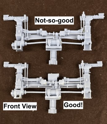
5IP Sighting Sys Comparison 1.jpg [ 1.29 MiB | Viewed 377 times ]


And the rear view that will be seen from the mount's interior.

Attachment:
5IP Sighting Sys Comparison 2.jpg
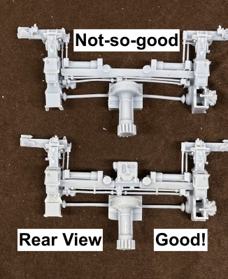
5IP Sighting Sys Comparison 2.jpg [ 1.68 MiB | Viewed 377 times ]


After doing a trial fit I was rewarded with a pretty good result.

Attachment:
5IP Sighting System Test Front.jpg
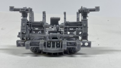
5IP Sighting System Test Front.jpg [ 1.77 MiB | Viewed 377 times ]


And the interior view.

Attachment:
5IP Sighting System Test Rear.jpg
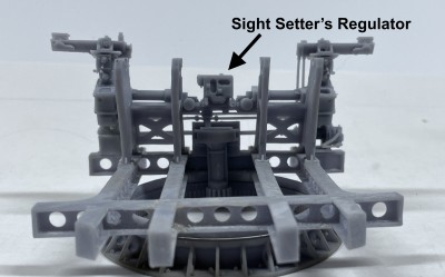
5IP Sighting System Test Rear.jpg [ 1.56 MiB | Viewed 377 times ]


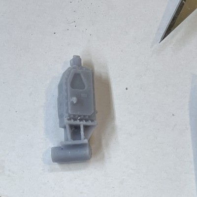
While this was printing I designed the Fuze Setter's Regulator. This assembly is also connected to the front complexity, but is very close to the starboard side gun mount. I decided to print it as a separate part and will install it after installing the guns so I can get the trunnion cap in place. This device is used to translate the firing timing from the gun directors into the fuze setting system in the projectile hoist. It was mostly obsoleted when the proximity fuze was introduced later in WW2.

Attachment:
5IP Fuze Setter's Regulator.jpg
5IP Fuze Setter's Regulator.jpg [ 820.01 KiB | Viewed 377 times ]


I've created masters for decals for all of these systems to simualate their dials.

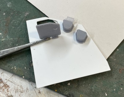
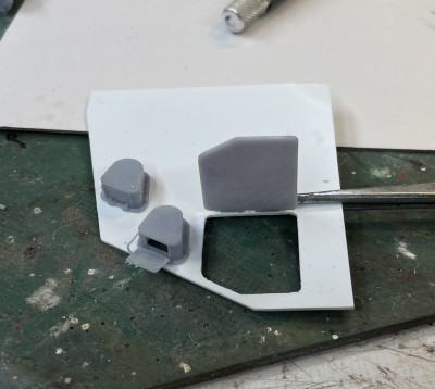
I redesigned the acess doors with the hinges in the open position to show the insides and how the system were maintained. I also redesigned the optics hood with the open shutter so the shutter had more beef in the hinge so this fragile part had a good survival chance.

Attachment:
5IP Open Side Panel.jpg
5IP Open Side Panel.jpg [ 888.9 KiB | Viewed 377 times ]


Attachment:
5IP Telescope Shields.jpg
5IP Telescope Shields.jpg [ 859.21 KiB | Viewed 377 times ]


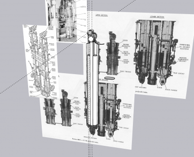
I'm now working on another complex unit, the projectile hoist. There are two of them, but they are not mirrored. They extend over two decks since they start in the Ready Service Room (RSR) before the gun house, pass through the center and end up in the gun house. I'm creating them this way. There are some structural steel cross-braces that support them. They do not go to the RSR's floor. They hang above it and the whole deal rotates with the turret. Unlike the big guns where the entire deck rotates to keep the hoist aligned with their respective guns, in the smaller 5" application, the hoist rotates, but the RSR is stationary.

Attachment:
5IP Projectile Hoist.png
5IP Projectile Hoist.png [ 1.14 MiB | Viewed 377 times ]


It's very complicated to created curves on already curved surfaces in SU. You can't do the simple push-pull extrude operation because that only works when the two sides are parallel. To cut a curve into another curve, you have to created a negatively-shaped "cutter" and use it with an extension called BoolTools2, to remove the interferece area and create the shaped surface. You can also do this directly in SU with "Intersect Faces", but you have a lot of clean up work since it gives you the cutting line, but leaves an open space that you must hand draw all the interconnecting lines to create a closed solid.

Attachment:
5IP Proj Hoist Upper Works.png
5IP Proj Hoist Upper Works.png [ 567.37 KiB | Viewed 377 times ]


While doing all this I finally finished that cute little n-gauge display layout that's going into the Newtown Hardware House in Newtown, PA. I was able to accurately model four Newtown buildings. These were drawn in SU using actual and Google Earth images.

Attachment:
NHH160 Finished 1.jpg
NHH160 Finished 1.jpg [ 3.09 MiB | Viewed 377 times ]


I have the Trumpeter 1:32 F35b on layaway at Scale Reproductions, Inc. I was waiting for the most complex F35 to finally come out in 1:32. While I'm not a big Trumpeter fan, they're the only one making this model now, so I'm going to get it. It will be 2024 when I start it so stay tuned.


Report this post
Top
 Profile  
Reply with quote  
PostPosted: Tue Dec 05, 2023 8:33 am 
Offline
User avatar

Joined: Tue Feb 22, 2011 7:45 pm
Posts: 139
It took over a week to draw the projectile hoist. It's complex, ambiguous in parts, had penetrations and curve cuts that needed shape cutting, and finally, required some major rework to get it as right as I can.

The rework was this.

Attachment:
Screenshot 2023-12-04 at 10.25.54 PM.png
Screenshot 2023-12-04 at 10.25.54 PM.png [ 226.11 KiB | Viewed 301 times ]


This central core had gotten so messed up with multiple diameter layered in on each other which created voids, reversed faces, and other anomalies that I couldn't get a decent solid image on the slicer in my tests. I finally bit the bullet and stopped screwing around with it and redrew it from scratch. This time it was perfect. All the discontinuities that plagued me were now gone.

I also figured out the routing of the handwheel linkages. Speaking of handwheels, I wanted to make sure that they would print perfectly since they're quite frail even when perfect. If there were joints that weren't true, it wouldn't hold up. That took a couple of hours.

And speaking of hours, it took an entire afternoon to get the doors right. Again, when I put them on the slicer surfaces were showing up as invisible. The "Solid Inspector 2" add-in kept showing surface interface irregularities. I when inside the object using the x-ray function and removed all non-functional surfaces and made sure all the face surfaces were perfectly tight. I was rewarded with beautiful objects in the slicer.

One of my other forums is SketchUp's. I post this in its entirety in five forums. The readers in the SU forum are expert artists and offer good suggestions. One was to not scale the 1:1 object in a 1:48 file, but instead, just load the 1:1 object in the slicer and do the scaling right there saving a whole range of copy/paste operations. With this massive file, those take a lot of time. Another suggestion was to set a camera scene facing directly at the tiny 1:1 component so with a click of the track pad, the 1:1 is instantly brought into the center of view. Otherwise, I have to keep zooming in many times to get the object to fill the screen. These zooms take a lot of time with big files.

Here's the finished object Front view:

Attachment:
5IP Projectile Hoist Comp Frt.png
5IP Projectile Hoist Comp Frt.png [ 2.64 MiB | Viewed 301 times ]


And the rear view:

Attachment:
5IP Projectile Hoist Comp rear.png
5IP Projectile Hoist Comp rear.png [ 2.52 MiB | Viewed 301 times ]


I'm going to attempt to print at least this part of the hoist system as a single part. Here's the part sitting on the slicer. It seems perfect. Will all of the intricacies print... who can tell. I only know when it's finished. That's the fun of 3D printing.

Attachment:
Screenshot 2023-12-04 at 11.13.36 PM.png
Screenshot 2023-12-04 at 11.13.36 PM.png [ 208.79 KiB | Viewed 301 times ]


I can now work on the powder hoist part of the system. This should be easier since there is no fuze setting linkage, only a single channel per side, sinpler doors, etc. There is one complication; the chute follows a curve and seems to change diameter.


Report this post
Top
 Profile  
Reply with quote  
PostPosted: Sun Dec 10, 2023 3:39 pm 
Offline
User avatar

Joined: Tue Feb 22, 2011 7:45 pm
Posts: 139
Thanks!

While it took less time to design the powder hoist portion of this system, it still took 6 days to do it. It is singularly, the most complex SketchUp work I've ever done. This still conforms to my goal for each project I take to push the envelope further and keep increasing my skills. It had all the same ambiguous drawings as the projectile side, plus some more complex geometry, little links that had to be ferreted out as to their purpose and destination. And finally, I had to keep imagining how it was going to print and ensure that every surface and every little appendage was fully solid and attached properly to all the other parts so it would print with integrity. When it was all done, I did one final fit into the master turret drawing and found that the powder hoists were spaced about 2" on each side too wide. Luckily, moving them inwards didn't create any new problems. They have to slip between the main frame rails. I could have trimmed the rails during assembly, but that seemed like cheating.

I incorporated that fully-modeled diamond-plate floor with the hoists to facilitate wrapping the plates around the protruding hoists and to add another piece of structure to keep their spacing.

This view shows the lower portion of the projectile hoist with their respective access doors. I modeled one open with projectile ready to go up to the gun house and the other closed. This is an accurated depiction since its upper doors are open with another projectile ready to be placed in the gun tray.

Attachment:
5IP Hoist Comp Frt.jpg
5IP Hoist Comp Frt.jpg [ 225.28 KiB | Viewed 149 times ]


Those manual handwheels are going to be very delicate. If they don't hold up when printing with the entire assembly, I'll print some separately and add them later.

The reverse view shows the powder hoists and the little aspect that pokes through the floor. There is an operating foot pedal that's also above the floor plates.

Attachment:
5IP Hoist Comp rear.jpg
5IP Hoist Comp rear.jpg [ 244.76 KiB | Viewed 149 times ]


I learned how to find and edit materials in the V-Ray rendering engine that's part of my new SketchUp installation. It's more complex to operate then my previous add-on renderer, Podium. It's also more sophisticated, faster (much faster) and does a much better rendering job.

I gave up on the idea of printing this beast in one piece. Instead I designed the two pieces so they will index together during assembly. I did this by adding some more structural steel at the bottom tying the two powder hoists to the central column. While this is not prototypical, I took artistic license to make the model work.

I also split the floor panels and added a lip to align and give purchase to the asembly joint.

Attachment:
Screenshot 2023-12-09 at 4.19.19 PM.png
Screenshot 2023-12-09 at 4.19.19 PM.png [ 448.95 KiB | Viewed 149 times ]


Here's the mess of supports needed to set it up for printing.

Attachment:
Screenshot 2023-12-10 at 11.41.32 AM.png
Screenshot 2023-12-10 at 11.41.32 AM.png [ 828.35 KiB | Viewed 149 times ]


It's on the printer now and will be done after 10pm. I'll know then whether it's successful or not. Then I'll have to figure out how to remove all those supports without wrecking anything. Wish me luck.

This was the last of the really complicated parts on the project. The rest is downhill.


Report this post
Top
 Profile  
Reply with quote  
Display posts from previous:  Sort by  
Post new topic Reply to topic  [ 31 posts ]  Go to page Previous  1, 2

All times are UTC - 6 hours [ DST ]


Who is online

Users browsing this forum: No registered users and 4 guests


You can post new topics in this forum
You can reply to topics in this forum
You cannot edit your posts in this forum
You cannot delete your posts in this forum
You cannot post attachments in this forum

Jump to:  
Powered by phpBB® Forum Software © phpBB Group