The Ship Model Forum

The Ship Modelers Source
It is currently Tue Apr 16, 2024 11:34 am

All times are UTC - 6 hours [ DST ]


Post new topic Reply to topic  [ 196 posts ]  Go to page Previous  1, 2, 3, 4, 5 ... 10  Next
Author Message
PostPosted: Sat Mar 05, 2016 5:54 pm 
Online
User avatar

Joined: Mon Oct 13, 2014 5:39 pm
Posts: 668
Location: San Tan Valley Arizona
Okay: I have been on a road trip to the West Coast but am now back at the bench. I managed to get the halyards attached. I made "canvas" tarps From Tissue and used AK Interactive Ship Weathering Colors AK303 for the wash on the Tissue. I also rigged the yards on the radar platform and attached a pulley, off a GM 1/350 Modern New Jersey sheet, at the center of the base for the CAXM-1 Radar platform. I used Bob's Buckles eyelets and tubes for rigging attachment points.

Image

In this photo you can clearly see the rigging and the center pulley coming off the yards and support of the Radar Platform.

Image

In scoping out the photo's of BB-38 at Mare Island in the Feb-Mar '42 time frame I noticed a set of "wires" Leading from the sides of the fore top to attachment points on the superstructure, so I replicated that here. I am not sure if these are antenna leads or just stays. I painted the tubes white simulating insulators in the event they are antenna leads.

Image

I also added what appears to be a weather van, and anemometers to the lattice yard and a hand rail. The fun part about attaching the halyards was that the starboard yard popped off. Always fun to replace when it is rigged. I initially used CA glue to attach it to the foretop, but after knocking the port one off, I reattached them using Testors Canopy cement. I Think it works much better than CA as it is a little more forgiving. Having knocked the lattice yards off my 1/200 Arizona Twice per side, I took the precaution of using pieces of sheet plastic as supports and placement points. It isn't per the original which has an "X" support, but it sure helps in re-setting the yards once they have popped off.

Image

This bottom one shows the ladder work to the platform on the foremast fore support where the bell would have been. It was difficult to see exactly what is on or underneath the platform so I put "something" there. The ladders are from the kit supplied PE.

Image

I got the cranes from Model Monkey via Shapeways. They are a work of art so that is the focus of the next step now that the superstructure is "finished."

Thanks for stopping by.

_________________
Mark
Master Gunnery Sergeant USMC (Ret.)
http://www.modelshipgallery.com/gallery ... index.html

On the bench:

1/200 USS Enterprise, CV-6


Last edited by Mgunns on Wed Mar 30, 2016 8:34 pm, edited 1 time in total.

Report this post
Top
 Profile  
Reply with quote  
PostPosted: Sat Mar 05, 2016 6:07 pm 
Offline
User avatar

Joined: Sat Jan 08, 2005 7:29 pm
Posts: 1284
Location: Tempe, Arizona
Looks excellent Mark :thumbs_up_1:

_________________
-Abram


Report this post
Top
 Profile  
Reply with quote  
PostPosted: Sun Mar 06, 2016 12:44 am 
Offline
User avatar

Joined: Mon May 14, 2012 12:18 pm
Posts: 2068
Location: Salt Lake City, USA
Good to see progress! This is turning out to be a very cool project and something I want to do myself someday.

A couple questions... I see the 3d printing layers in some of the photos. Do they detract from the finished object when seen without the "benefit" of macro-photography?

Have you tried to clean any of the surfaces up to get rid of the layering and if so, what method works? Are the parts too brittle for regular styrene/resin scraping and/or sanding?

_________________
-Jason Channell

Current Project: 1/200 Bismarck


Report this post
Top
 Profile  
Reply with quote  
PostPosted: Sun Mar 06, 2016 10:33 am 
Online
User avatar

Joined: Mon Oct 13, 2014 5:39 pm
Posts: 668
Location: San Tan Valley Arizona
Thanks Abram for your comment and thanks for stopping by.

@ Jason: There are some areas that show the 3D Layering. The air defense structure being the chief one. It is molded into the superstructure and very difficult to get a sanding stick on it. It isn't as noticeable with the naked eye. The rest of the structure I used sanding sticks and 320 to 600 grit sand paper and then a wash with Dawn dish soap and a tooth brush. The macro lens shows these but looking at it from normal viewing distance and even up close they all but disappear. This is my first foray into 3D printed parts and it is a learning process as well. The time consuming part is the measuring, checking references for locations of gear, identifying the gear and the location thereof, re-measuring and re-checking as there are no instructions or locating holes for the fittings. So the old axiom, measure twice, drill once holds true.

Thanks for stopping by and your interest in the project.

_________________
Mark
Master Gunnery Sergeant USMC (Ret.)
http://www.modelshipgallery.com/gallery ... index.html

On the bench:

1/200 USS Enterprise, CV-6


Report this post
Top
 Profile  
Reply with quote  
PostPosted: Sun Mar 06, 2016 11:09 am 
Offline
User avatar

Joined: Wed Nov 17, 2010 10:51 am
Posts: 382
Location: S.C.
Mark this is a very exciting conversion you have going on and I've taken an interest since the start of this thread, You see I started a Pennsy (3/42 Mare) conversion back last summer using the 1/350 Banner kit. At the time the Printed parts weren't out there yet so I had scratched out the SS and square tower around the Funnel area. From your work photos I see where I have gotten several of the details wrong so I have put the build in limbo while I follow along with your progress.

My choices at the moment are to leave it as is and call it a "Arizona survived Pearl Harbor WIF" ,or tear it down and start over with the correct Printed parts..

Wonderful work you are doing here....I've got a supply of popcorn and a comfy chair :)


Report this post
Top
 Profile  
Reply with quote  
PostPosted: Sun Mar 06, 2016 3:14 pm 
Online
User avatar

Joined: Mon Oct 13, 2014 5:39 pm
Posts: 668
Location: San Tan Valley Arizona
Hello Gott_cha:

Seeing as you have gotten that far, I would tear it down and use the Model Monkey 1/350 Superstructure. It really is a work of the 3D printers art. I have one as well, don't know why, now that I have this 1/200 going. If you would be interested I would be willing to sell you the 1/350 Pennsy set that I have, it is in perfect condition and will definately enhance your effort, if not, I will build the 1/350 version of what I am doing in 1/200. As the cranes are totally different on Pennsy vice Arizona, I would highly recommend getting them from Model Monkey to round out your Pennsy build.
Thanks for following along and your encouragement. I will continue to post updates as they occur.

_________________
Mark
Master Gunnery Sergeant USMC (Ret.)
http://www.modelshipgallery.com/gallery ... index.html

On the bench:

1/200 USS Enterprise, CV-6


Report this post
Top
 Profile  
Reply with quote  
PostPosted: Wed Mar 09, 2016 11:21 am 
Online
User avatar

Joined: Mon Oct 13, 2014 5:39 pm
Posts: 668
Location: San Tan Valley Arizona
Okay: I managed to get one the starboard crane finished. This is the Model Monkey 1/200 Crane assembly. I painted it overall Tamaiya XF-24. For the eyelets for attachment Points I used Bob's Buckles eyelets for 1/32nd aircraft. They are pretty much in scale and are most helpful in attaching rigging. I used fine EZ line for the rigging and cable. The PE comes from the Eduard Crane set, Kit PE. I had to cut out the middle rail of the kit provided 3 bar railing, and some scrap GMM 1/350 Modern New Jersey and Enterprise sets. I also used the kit provided hook and pulley assmebly with the kit provided PE cable for the hook and pulley. For the end weighted hook I used Evergreen # 222, 1/16 rod cut to 3/16 of an inch and drilled for rigging and the hook assembly, which again came from the GMM 1/350 Modern New Jersey and some fine copper wire out of an old electrical box. I dry brushed the crane Testors MM intermediate Grey, but any gray would work to pick out some of the details. The flash washed a lot of it out and the color is a lot lighter than the actual crane, but you can see the detail that is in the crane that Model Monkey provides. For the top bracing, I used the Eduard PE provided in their 1/200 Arizona crane set, trimmed to fit. Once I figured it all out, the port crane is going together a lot more smoothly. Anyone doing this conversion in any scale, the cranes are a must and Model Monkey provided an excellent source for those cranes; it takes all the guess work out of it. Oh, and don't forget to cut the light fixtures off the kit crane as Pennsylvania had them as well.


Image

Image

Image

_________________
Mark
Master Gunnery Sergeant USMC (Ret.)
http://www.modelshipgallery.com/gallery ... index.html

On the bench:

1/200 USS Enterprise, CV-6


Report this post
Top
 Profile  
Reply with quote  
PostPosted: Wed Mar 09, 2016 4:23 pm 
Offline
User avatar

Joined: Sat Jan 08, 2005 7:29 pm
Posts: 1284
Location: Tempe, Arizona
That crane looks fantastic! My 1/700 versions should be here any day now, I hope I can build them to look that nice.

_________________
-Abram


Report this post
Top
 Profile  
Reply with quote  
PostPosted: Wed Mar 09, 2016 5:29 pm 
Offline
Model Monkey
Model Monkey

Joined: Sat Aug 20, 2005 9:27 pm
Posts: 3954
Location: USA
:big_grin:

_________________
Have fun, Monkey around.™

-Steve L.

Complete catalog: - https://www.model-monkey.com/
Follow Model Monkey® on Facebook: - https://www.facebook.com/modelmonkeybookandhobby


Report this post
Top
 Profile  
Reply with quote  
PostPosted: Wed Mar 09, 2016 10:36 pm 
Offline
User avatar

Joined: Tue Aug 25, 2015 1:33 pm
Posts: 489
Location: Grand Rapids, Michigan
Wow Mark, that's nothing short of spectacular! Simply Beautiful!

_________________
Larry Steiner


Completed: 1:200 USS Missouri (Monster Mo)
Next project: Definitely NOT another big ship!!


Report this post
Top
 Profile  
Reply with quote  
PostPosted: Thu Mar 10, 2016 8:26 pm 
Offline
User avatar

Joined: Mon Nov 18, 2013 3:41 pm
Posts: 2948
Location: Mocksville, NC
Mark,

You've done a spectacular job so far - Kudos!!! I'll refer to this on my PENNSY build. The additional wire you added above the yardarm is a radio antenna with the usual insulator on each end.

Hank

_________________
HMS III
Mocksville, NC
BB62 vet 68-69

Builder's yard:
USS STODDARD (DD-566) 66-68 1:144, Various Lg Scale FC Directors
Finished:
USS NEW JERSEY (BB-62) 67-69 1:200
USN Sloop/Ship PEACOCK (1813) 1:48
ROYAL CAROLINE (1748) 1:47
AVS (1768) 1:48


Report this post
Top
 Profile  
Reply with quote  
PostPosted: Fri Mar 11, 2016 12:12 am 
Online
User avatar

Joined: Mon Oct 13, 2014 5:39 pm
Posts: 668
Location: San Tan Valley Arizona
Hi guys and thanks for looking in and your comments, all duly appreciated. No pictures as I am finishing up the port crane and then moving on to the guns. It may be awhile until I post something meaningful and Pennsylvania related.
Until that time

_________________
Mark
Master Gunnery Sergeant USMC (Ret.)
http://www.modelshipgallery.com/gallery ... index.html

On the bench:

1/200 USS Enterprise, CV-6


Report this post
Top
 Profile  
Reply with quote  
PostPosted: Wed Mar 30, 2016 12:32 pm 
Online
User avatar

Joined: Mon Oct 13, 2014 5:39 pm
Posts: 668
Location: San Tan Valley Arizona
Okay folks:

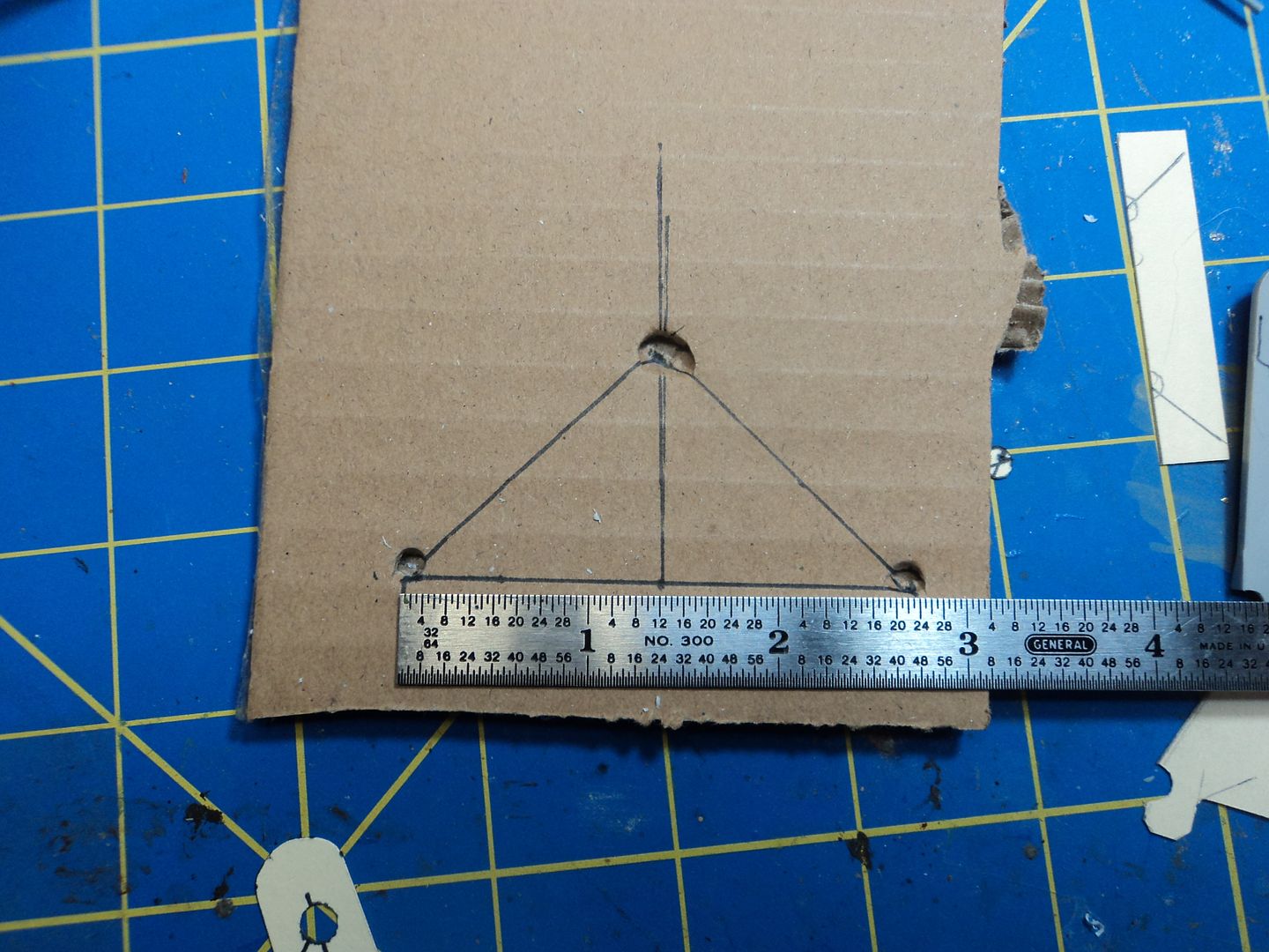
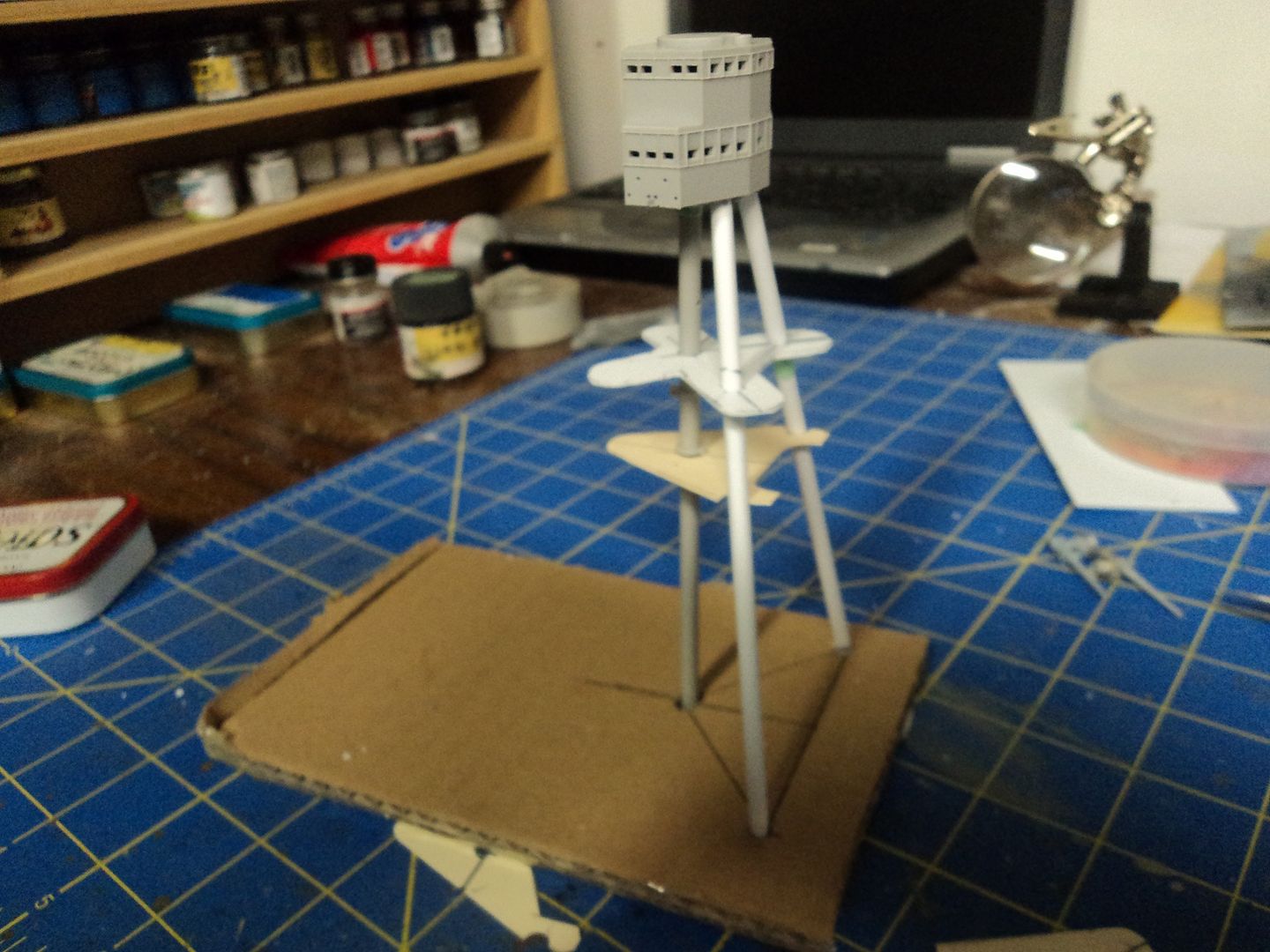
I have been working on the secondary armament and the main mast. I won't post the secondary armament as it is no different than the Arizona's and there are lots of photo's of them elsewhere. The main mast is quite a bit different than the Arizona. For starters the "Splay" of the two fore legs is much different. The legs but up against the bulkhead that separates the main deck from the Superstructure deck and against the kingposts of the cranes giving them a wider and shallower stance than the Arizona. What to do? I tried using the kit for starters as to placement of the legs. This didn't work as the main mast assembly kept falling apart. So I devised a simple cardboard jig with the measurements transferred to it. It works great.

Image

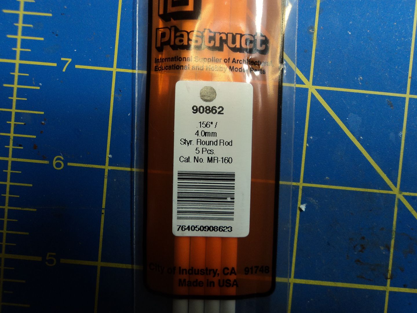
Then I needed to get rod stock to make the legs as the kit legs are too short. So I got some Plastruct 4mm rod that is about as perfect a match as one can get.

Image

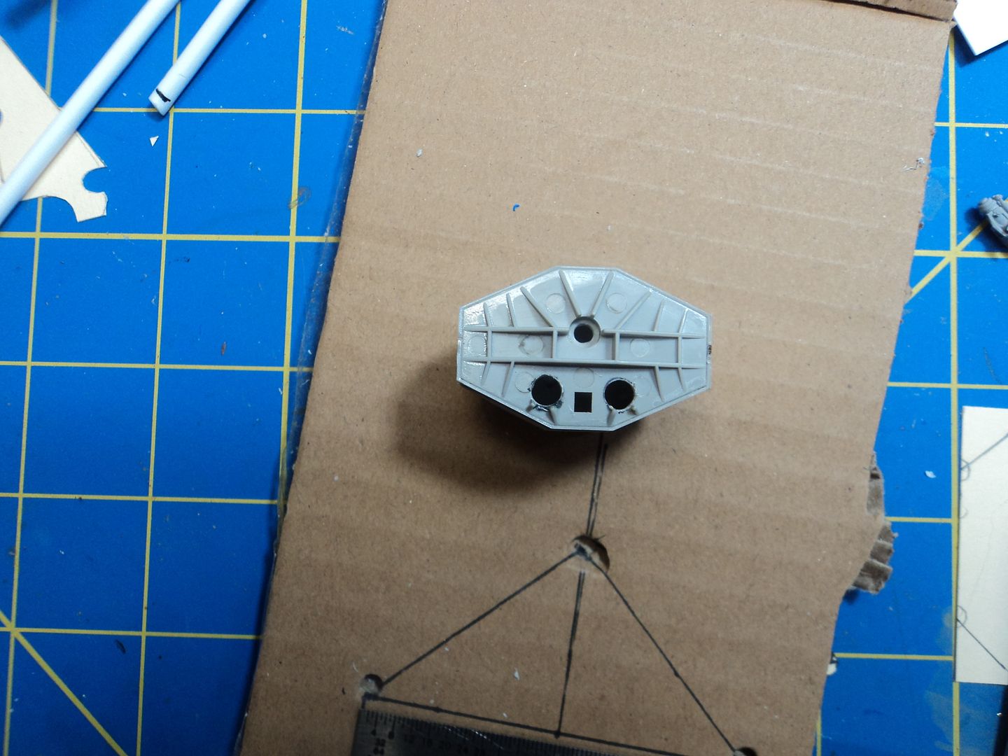
I then measured the length of the legs against my 1/200 drawing of the ship, added a bit for fudge factor and went to town. For starters I needed to drill holes in the underside of the top for the legs to sit in for alignment and flexibility.

Image

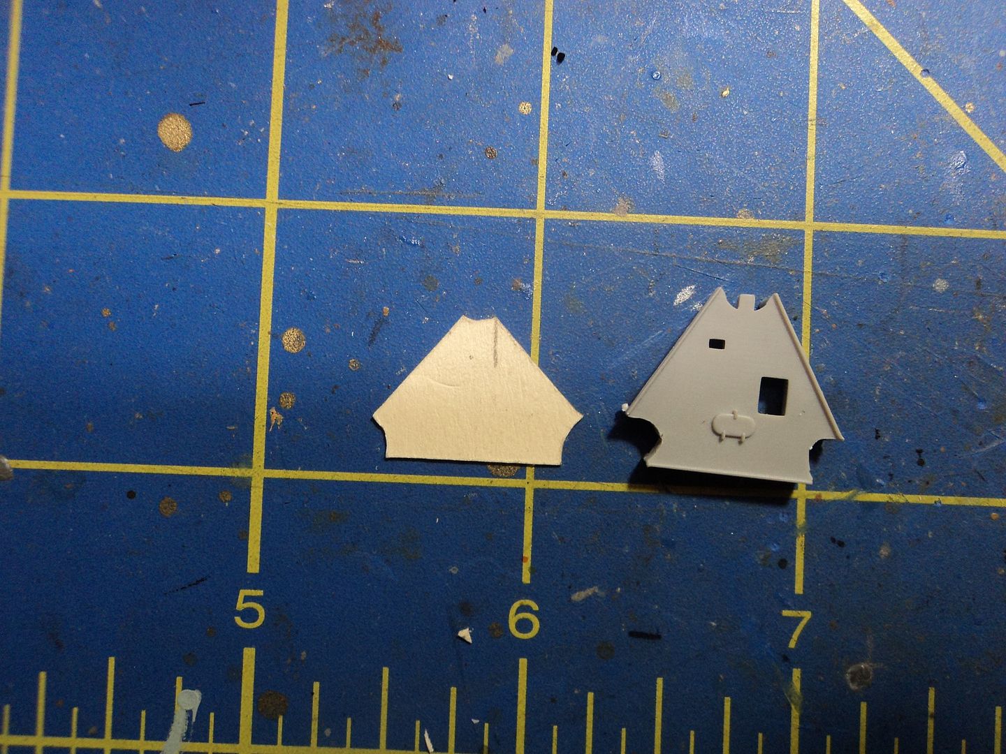
I then traced the "cloverleaf"/Searchlight platform off the drawing, transferred it to a piece of file folder stock and began to fit it to the assembly. Once I got it "right", I then transferred it to sheet plastic, cut and drilled and installed to see how it fit, I then moved on to the triangular platform below it. That was a tough one as if the alignment was off a hair, it wouldn't fit. After several attempts I finally got it right.

Image

Image

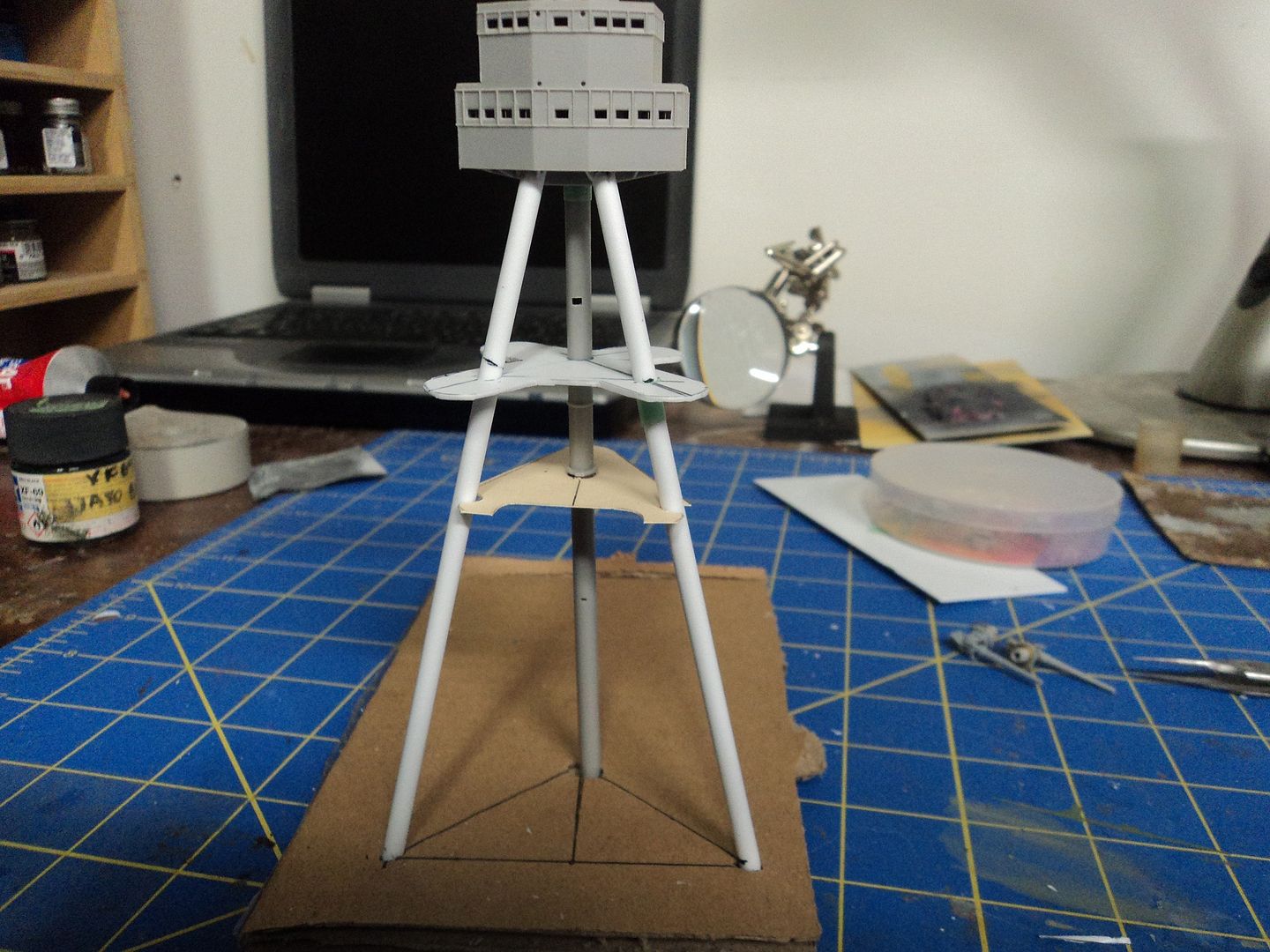
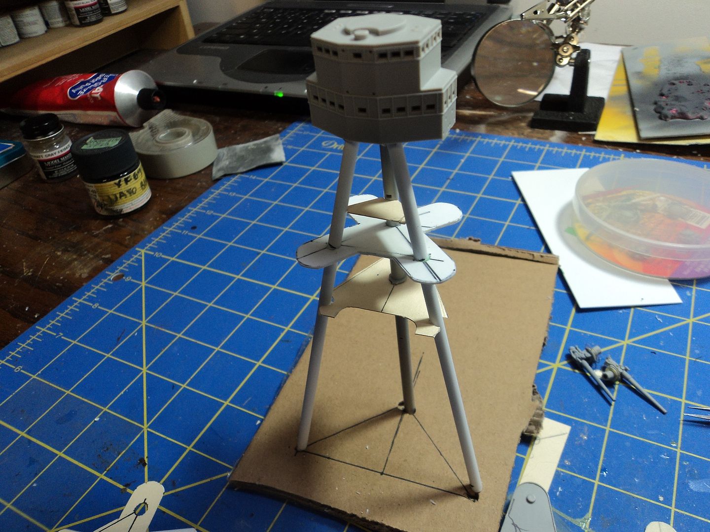
The last platform is a small triangular affair that sits above the searchlight platform, Arizona had one additional narrow platform above that, Pennsylvania did not. Here all three platforms are in place. The searchlight platform provides stability and alignment for the other two.

Image

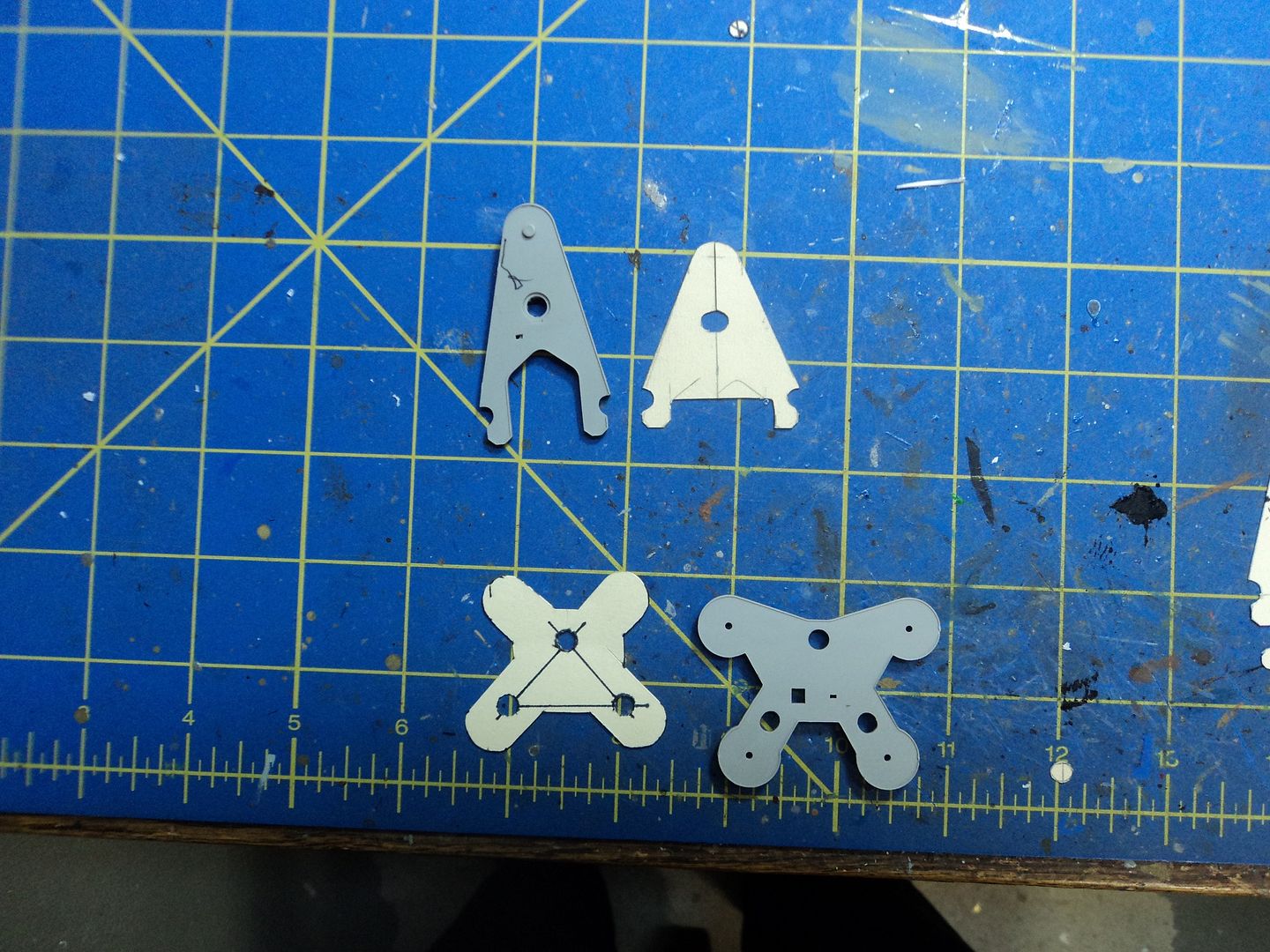
Here we see a comparison of the Arizona kit parts and the same parts as on Pennsylvania. As you can see the differences are quite dramatic.

Image

Image

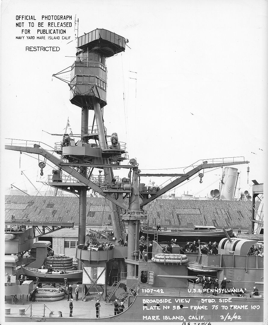
The searchlights on the cloverleaf platform will be a tight fit, but if you look at the actual ship you can see that they are situated pretty tight as well. I may have to adjust slightly, but after test fitting, they do fit, albeit pretty tight.

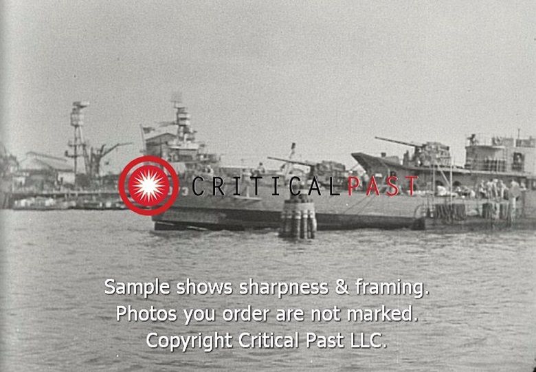
Granted, this photo is of Pennsylvania at Mare Island in Feb-March 1942 but it coincides with the distant photo of it at Pearl Harbor in December of 1941.

Image

Image

As you can see, a lot of work is left but; I am happy with the result I now have as I have overcome the alignment and spacing problem, I have the platforms that once transferred to sheet plastic will fit and I will have a robust structure that I can paint and assemble and as the old Revell Instructions used to admonish the modeler: "Set aside to dry."

_________________
Mark
Master Gunnery Sergeant USMC (Ret.)
http://www.modelshipgallery.com/gallery ... index.html

On the bench:

1/200 USS Enterprise, CV-6


Report this post
Top
 Profile  
Reply with quote  
PostPosted: Wed Mar 30, 2016 12:36 pm 
Offline
User avatar

Joined: Sat Jan 08, 2005 7:29 pm
Posts: 1284
Location: Tempe, Arizona
Mark, excellent work. That's good info on the mast too. Not I need to decide if I'll be doing this on my 1/700 build too. I wish I had your references.

_________________
-Abram


Report this post
Top
 Profile  
Reply with quote  
PostPosted: Wed Mar 30, 2016 12:41 pm 
Online
User avatar

Joined: Mon Oct 13, 2014 5:39 pm
Posts: 668
Location: San Tan Valley Arizona
Okay:

As Pennsylvania had two 3" 50's situated forward on the superstructure, I needed to put something in those tubs. So, while I am waiting for one of the 3D folks to come up with one in 1/200, I improvised with what I had. I noticed on the 5" Casemate guns that the assembly was "simliar" to the 3". Using the kit extra 5" as a base, I used the kit provided 5" 38 barrels. I am using the Trumpeter detail set which includes brass barrels for the secondary so I had an abundance of kit plastic 5" 38 barrels. They are shorter and seem to be a little smaller in bore, so I used those. The cylinders on top had to be adjusted to more closely represent the 3" version. I also noticed the seating arrangement, so, I had an extra fret of Eduard PE with seats and such for the searchlights and I Used that for the "3" gun. It isn't exact, but; I think it will be fine as to me it "Has the Look" and it fills the space. Once a 3D manufacturer does them, I will replace it with a more accurate rendering.

Below is a photo of the actual gun

Image

Mine

Image

Image

Image

As I mentioned above, it isn't exact and that wasn't my intention, my intention was to have something that looked like it.

_________________
Mark
Master Gunnery Sergeant USMC (Ret.)
http://www.modelshipgallery.com/gallery ... index.html

On the bench:

1/200 USS Enterprise, CV-6


Report this post
Top
 Profile  
Reply with quote  
PostPosted: Thu Mar 31, 2016 6:54 pm 
Offline
User avatar

Joined: Mon Nov 18, 2013 3:41 pm
Posts: 2948
Location: Mocksville, NC
Mark,

Once again, as you & I are keeping tabs on this, nice progress on the mast/guns, etc. I like the process you developed for the mast legs. I'll note the size of the legs for future purchase.

Hank

_________________
HMS III
Mocksville, NC
BB62 vet 68-69

Builder's yard:
USS STODDARD (DD-566) 66-68 1:144, Various Lg Scale FC Directors
Finished:
USS NEW JERSEY (BB-62) 67-69 1:200
USN Sloop/Ship PEACOCK (1813) 1:48
ROYAL CAROLINE (1748) 1:47
AVS (1768) 1:48


Report this post
Top
 Profile  
Reply with quote  
PostPosted: Fri Apr 01, 2016 10:02 am 
Offline
User avatar

Joined: Wed Nov 17, 2010 10:51 am
Posts: 382
Location: S.C.
Mark , great explanation on the mast spread and platform differences.
Would you be willing to send that "solution" over to Stephen Larson at MM.
The platforms could be printed in the popular scales and would be a great help to others in establishing the proper mast stance. I know for certain it would benefit a 1/350 conversion I will start soon as the desk Que is cleared.

Great work my friend...have been anxious for a new post... :thumbs_up_1: :)


Mark


Report this post
Top
 Profile  
Reply with quote  
PostPosted: Fri Apr 01, 2016 10:28 am 
Online
User avatar

Joined: Mon Oct 13, 2014 5:39 pm
Posts: 668
Location: San Tan Valley Arizona
Thanks guys for checking in and your comments:

@Mark: I would be glad to send these to Steve if he would want them. The only "catch" is these are based on the model and his stuff is based on measurements off the actual ship and drawings. There are so few good references for the Pennsylvania that it would be difficult for him to do one IMHO. BB62VET has a great drawing of the ship, I would send him a PM and see if he could scale it for you. That is what I am using.
I have yet to transfer these to plastic and will be doing so today, I am sure there will be some tweaking but overall it should go fairly well. It would be nice if Steve could do these, it would certainly take the guess work out of it.

@Abram: I would imagine that doing this in 1/700 would be much easier as the room for error is so small it could be easily adjusted. I found that once I made the cardboard jig and got the right material it went rather well, much better than I had expected. I would recommend the PSBB38 CD from Floating Dry Dock. That is almost my sole source for references. It also has a great section on the Arizona as well. Highly recommend it. Here is a link to the site, if you scroll down you will see the CD PSBB38, it's $19.95, money well spent. http://www.floatingdrydock.com/books.html

@BB62VET: Thanks Hank for checking in and your assistance in this build, all duly appreciated.

_________________
Mark
Master Gunnery Sergeant USMC (Ret.)
http://www.modelshipgallery.com/gallery ... index.html

On the bench:

1/200 USS Enterprise, CV-6


Report this post
Top
 Profile  
Reply with quote  
PostPosted: Fri Apr 01, 2016 10:43 am 
Offline
User avatar

Joined: Tue Jan 11, 2005 1:40 pm
Posts: 8174
Location: New Jersey
Very nice work. Love what you did with the main mast and how you both figured out and solved the differences in the tripod legs. Looking forward to seeing more. I have a 1/700 Midship Models 1941 Pennsy in the stash. I already have Steve's 1/700 forward superstructure, and will get the funnel and cranes eventually. Your conversion will be a handy reference when and if I ever get around to building the model.

_________________
Martin

"Tomorrow is the most important thing in life. Comes into us at midnight very clean. It's perfect when it arrives and it puts itself in our hands. It hopes we've learned something from yesterday." John Wayne

Ship Model Gallery


Report this post
Top
 Profile  
Reply with quote  
PostPosted: Fri Apr 01, 2016 11:46 am 
Offline
User avatar

Joined: Mon Nov 18, 2013 3:41 pm
Posts: 2948
Location: Mocksville, NC
Got Cha Mark wrote:
Quote:
Mark , great explanation on the mast spread and platform differences.
Would you be willing to send that "solution" over to Stephen Larson at MM.
The platforms could be printed in the popular scales and would be a great help to others in establishing the proper mast stance. I know for certain it would benefit a 1/350 conversion I will start soon as the desk Que is cleared.

MGunns Wrote:
Quote:
@Mark: I would be glad to send these to Steve if he would want them. The only "catch" is these are based on the model and his stuff is based on measurements off the actual ship and drawings. There are so few good references for the Pennsylvania that it would be difficult for him to do one IMHO. BB62VET has a great drawing of the ship, I would send him a PM and see if he could scale it for you. That is what I am using.
I have yet to transfer these to plastic and will be doing so today, I am sure there will be some tweaking but overall it should go fairly well. It would be nice if Steve could do these, it would certainly take the guess work out of it.

It may be possible that I could provide a 2D CAD drawing of the various platforms & Leg Template needed once I've constructed the ones I will need on my build. This would allow others to print out and use for their various needs. I can double/triple dimension the necessary parts in my CAD program thus letting one drawing work for several different scales. Scaled properly, a drawing such as this could be the template that others would need to make their own parts. It's also possible to make an 11"x17" drawing and provide the various parts needed for several scales all on one drawing. There are several ways to approach this problem and come up with a useable solution. I could put this on my future "to do" list.

The drawing MGunns refers to above is an overall scan I did of the 1935 PENNSY side view/overhead plan that came to me in two halves. I printed out the full size pages and carefully mated them together and have it scanned in as a .pdf @ 1:200 scale but can reduce as necessary for most normal modeling scales. This particular drawing was drawn showing PAs last major refit at Puget Sound in 1935, so it includes most of the "modernized" components of her prior to WWII.

Hope this helps,

Hank

_________________
HMS III
Mocksville, NC
BB62 vet 68-69

Builder's yard:
USS STODDARD (DD-566) 66-68 1:144, Various Lg Scale FC Directors
Finished:
USS NEW JERSEY (BB-62) 67-69 1:200
USN Sloop/Ship PEACOCK (1813) 1:48
ROYAL CAROLINE (1748) 1:47
AVS (1768) 1:48


Report this post
Top
 Profile  
Reply with quote  
Display posts from previous:  Sort by  
Post new topic Reply to topic  [ 196 posts ]  Go to page Previous  1, 2, 3, 4, 5 ... 10  Next

All times are UTC - 6 hours [ DST ]


Who is online

Users browsing this forum: No registered users and 22 guests


You can post new topics in this forum
You can reply to topics in this forum
You cannot edit your posts in this forum
You cannot delete your posts in this forum
You cannot post attachments in this forum

Jump to:  
Powered by phpBB® Forum Software © phpBB Group