Greetings Fellow Modelers-I was able to make some good painting progress this weekend!
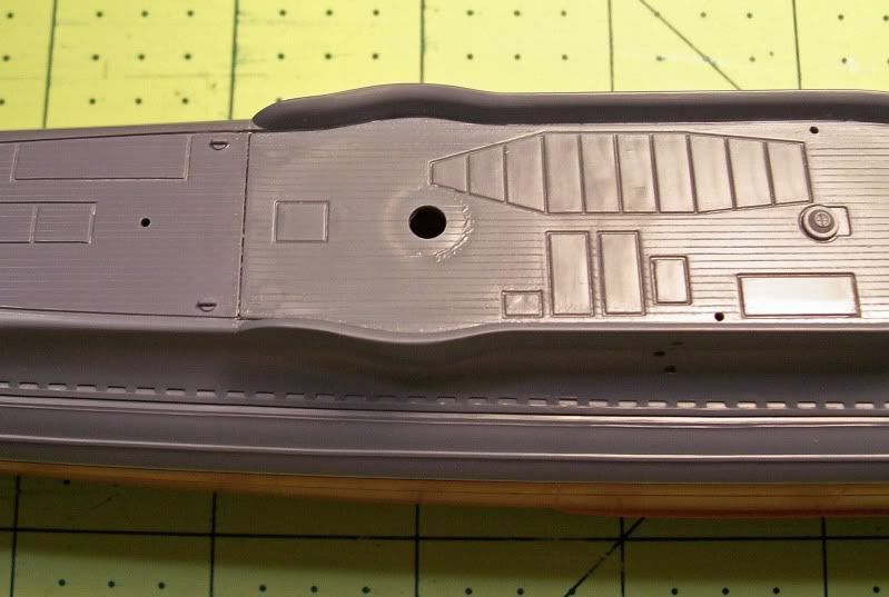
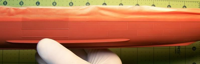
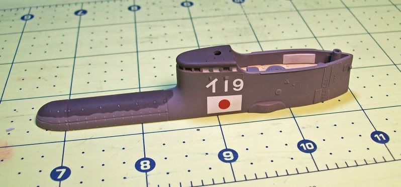
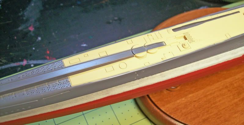
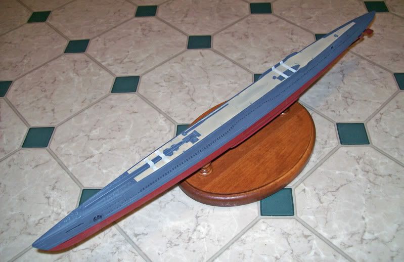
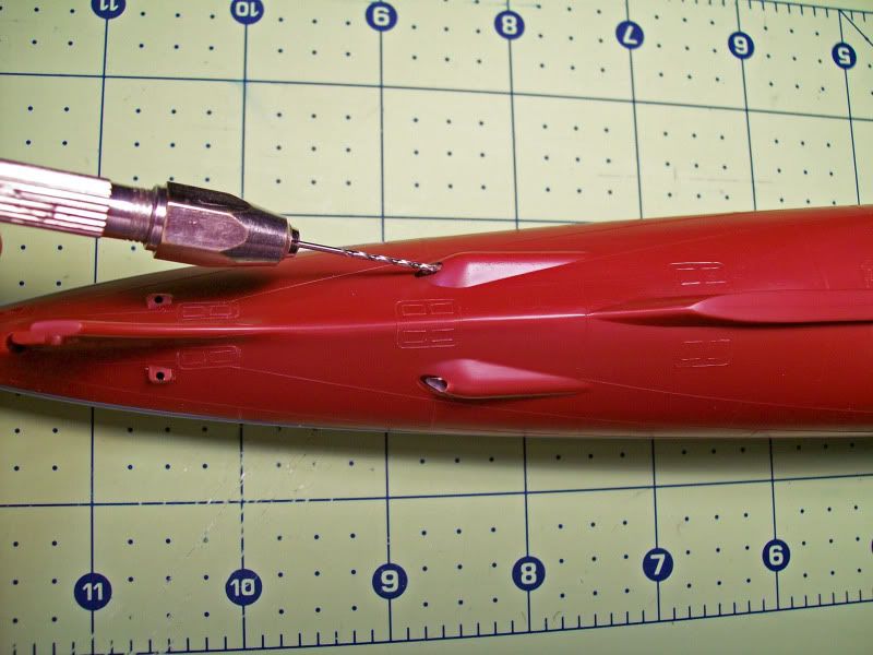
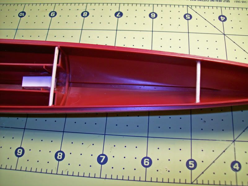
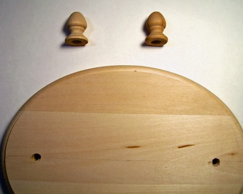
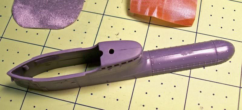
1st Image: After all of the painting on the lower hull was done it was permanently attached to the wooden base, which made handling much easier. The next section painted was the deck. I used Model Master radome tan, since it is a close match to the White Ensign deck color. This is a very light, bright color that almost looks like fresh cut pine. To prevent paint build up from multiple coats, the upper hull around the deck was masked off.
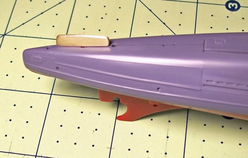
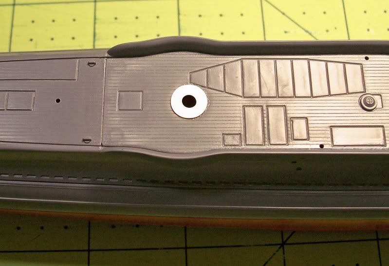
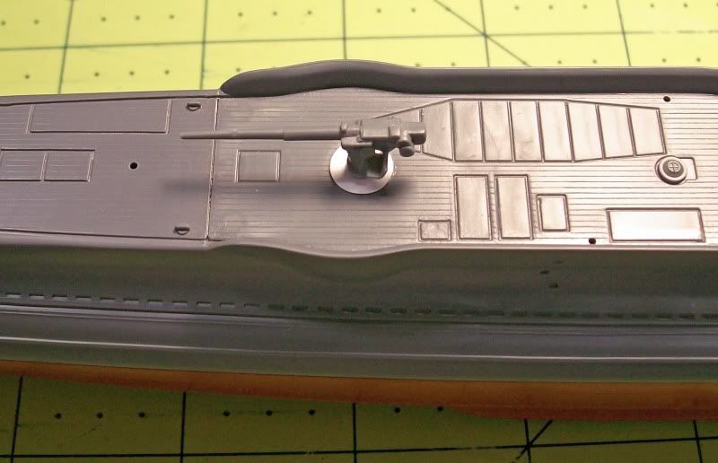
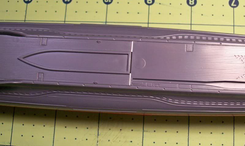
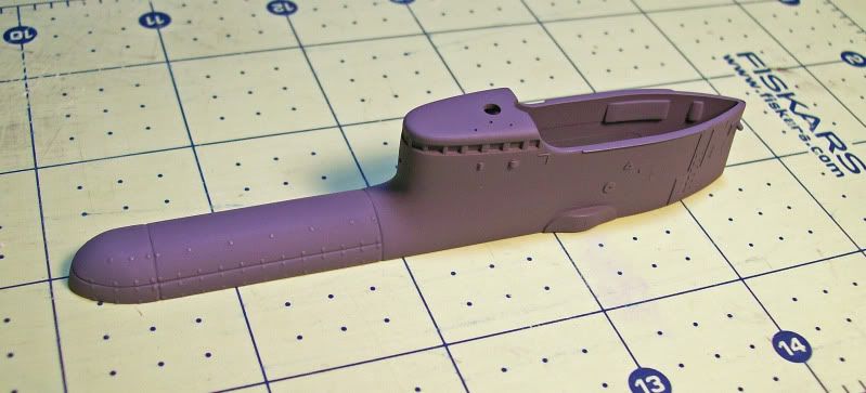
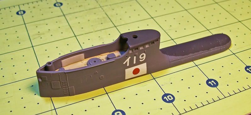
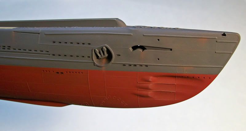
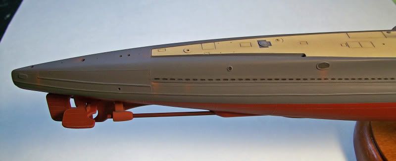
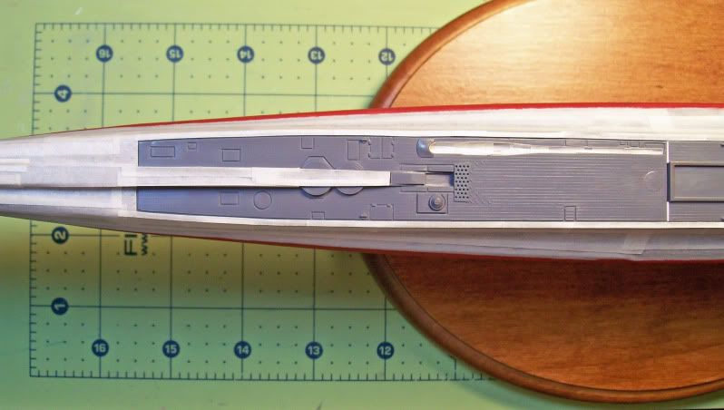
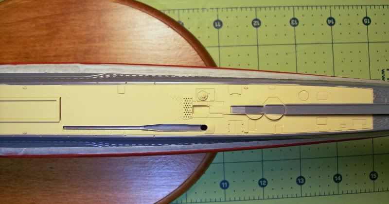
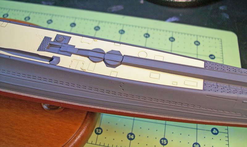
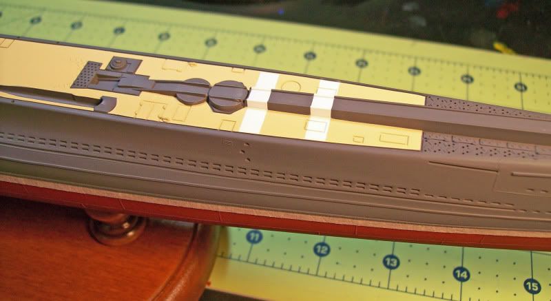
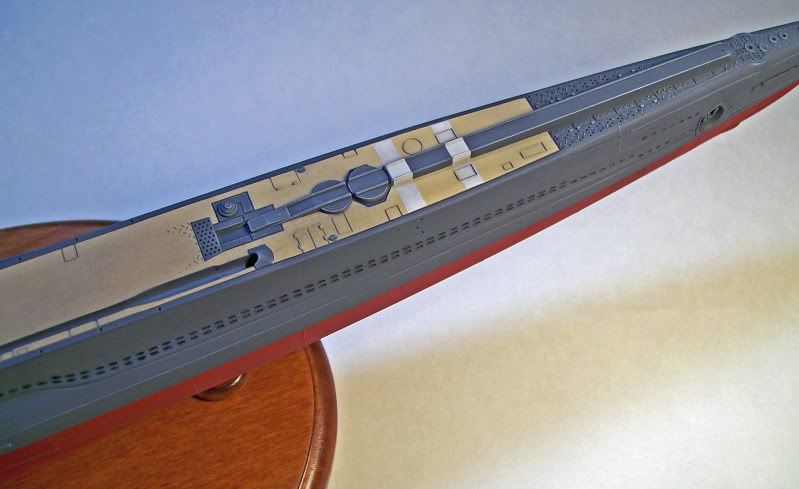
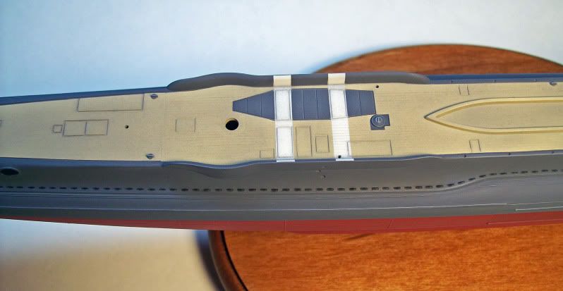
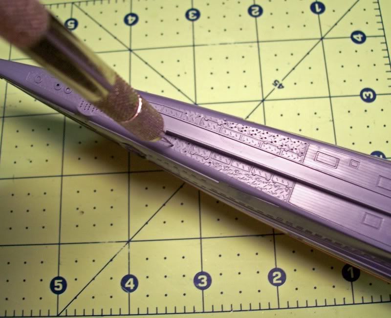
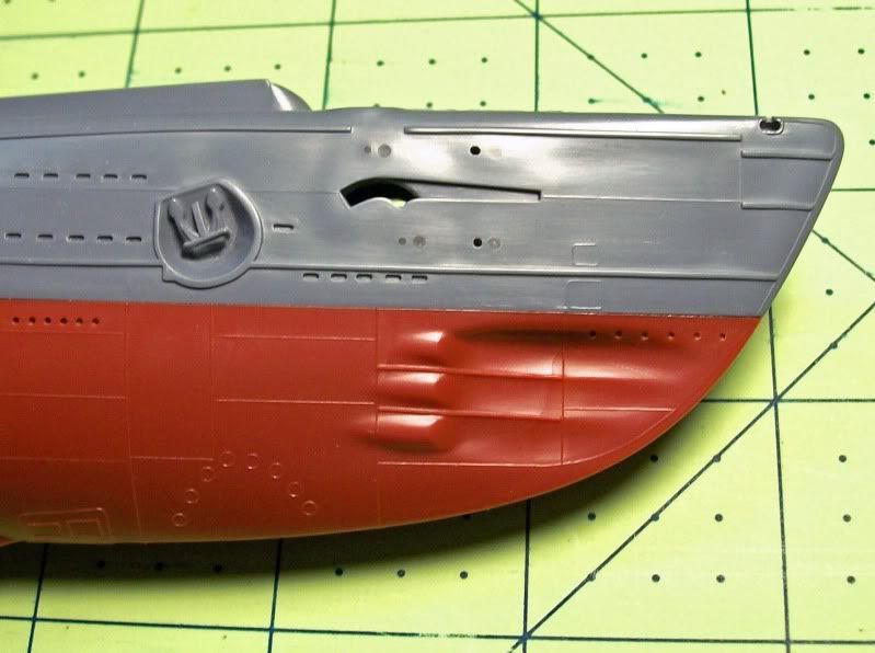
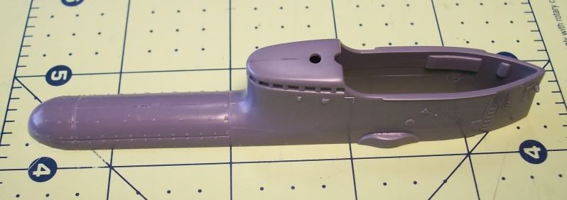
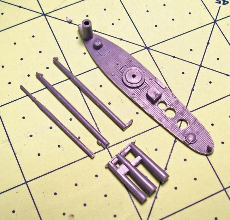
2nd and 3rd Images: These photos show the “base” tan color after the tape was removed.
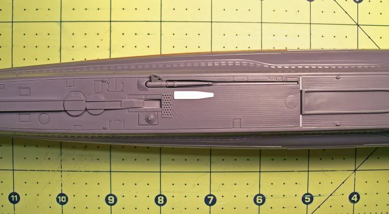
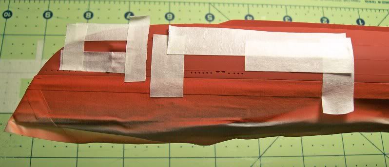
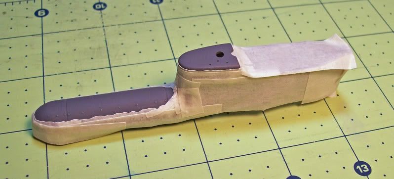
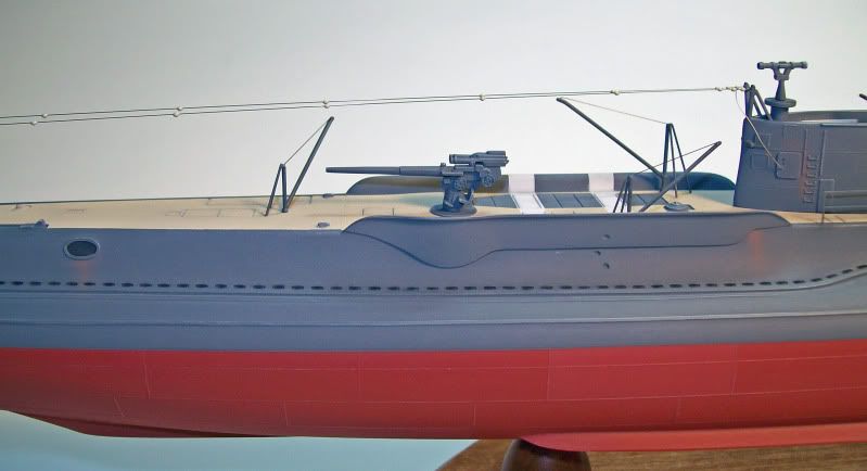
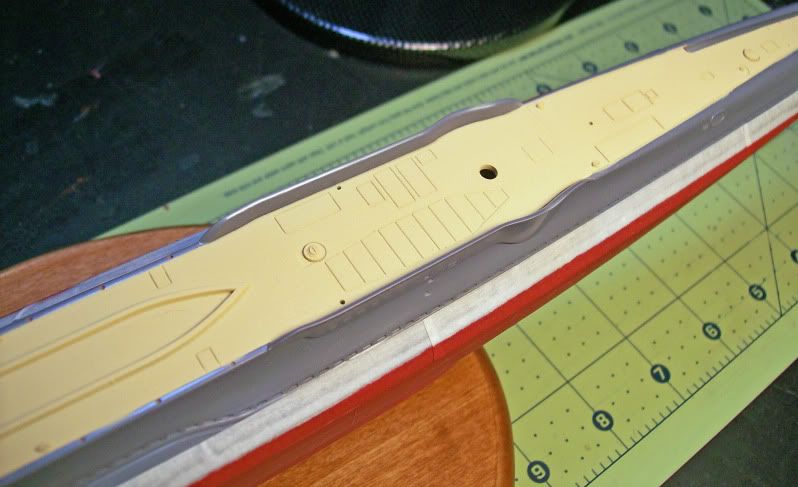
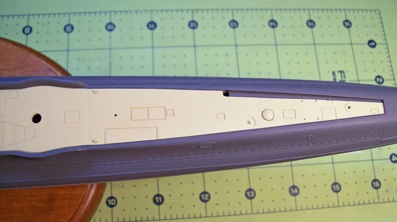
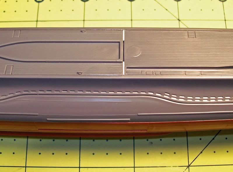
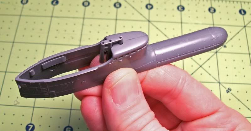
4th Image: Next, the painted deck area was masked off so the upper hull could be painted. A good masking job on this step is critical because it determines how sharp the painting details between the deck and upper hull will be. Note that some of the deck details that were painted tan are exposed so they can be painted gray. I used Model Master anthracite gray for the upper hull. Once again I felt it was a close to the White Ensign color.
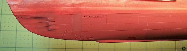
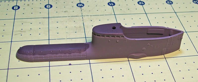
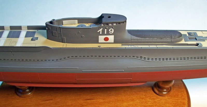
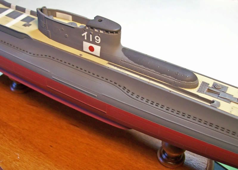
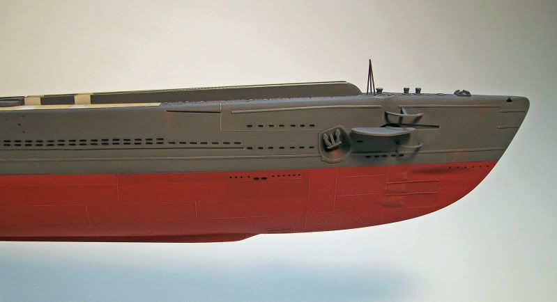
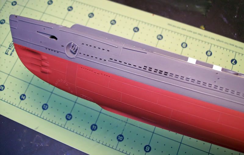
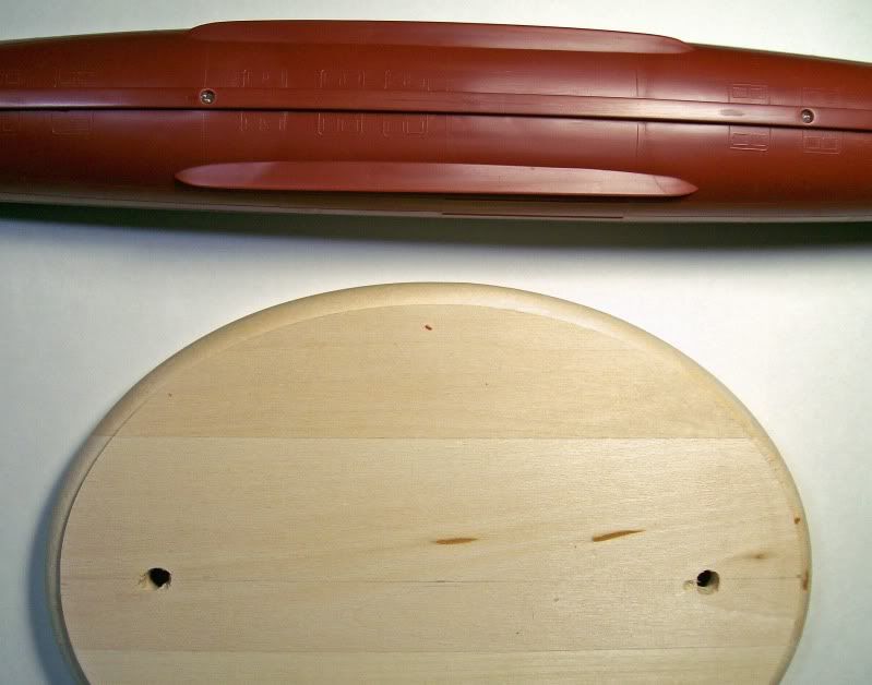
5th and 6th Images: These photos show the upper hull after the masking tape was removed from the deck.
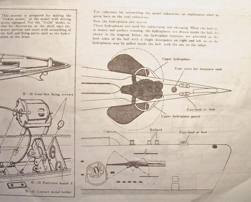
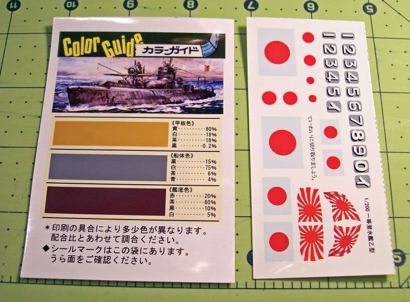
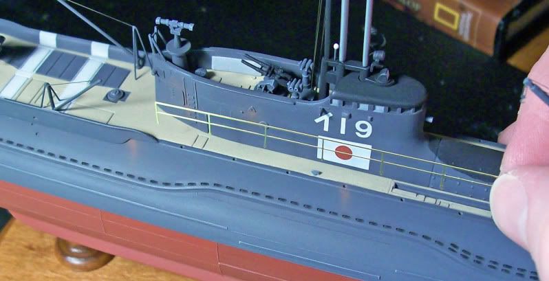
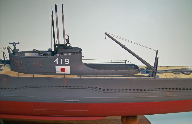
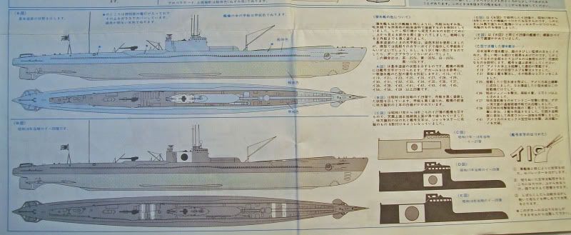
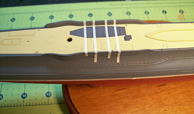
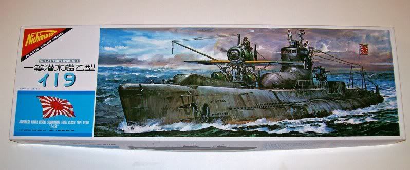
7th Image: This is part of the instructions that came with the Nichimo kit, showing painting suggestions. I used it to help locate the white identification bands (two forward/two aft). After a Japanese submarine was accidentally bombed by a Japanese airplane in May 1942, a directive was issued for submarines to have white recognition bands painted (or attached) across the deck. The location, shape and number of bands varied, but what is shown on this drawing is typical so it is what I used on my model.
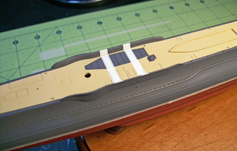
8th Image: This photo shows the beginning of the process to mask off the recognition bands. Note the cover plate over the lifeboat storage area has been painted anthracite gray.
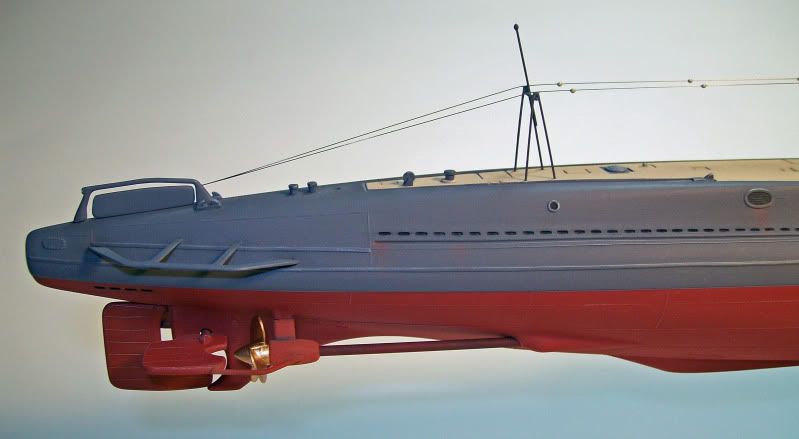
9th and 10th Images: Here are photos of the newly painted recognition bands. Note the paint colors are nice and pristine at this point, but will undergo a significant transformation after pastel weathering and dry-brushing are added.
11th Image: To give the flood holes a “hollow” appearance, black pastel powder was rubbed into each opening with a tiny paint brush. This was tedious task but it added a lot.
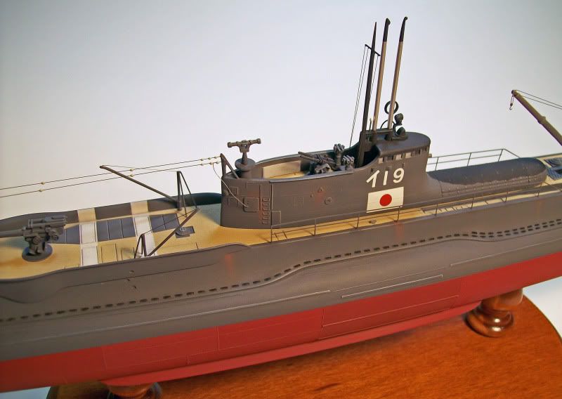
12th Image: This photo shows an overview of the hull.
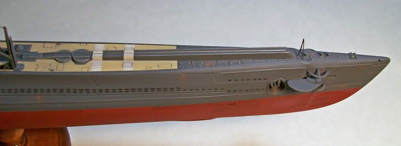
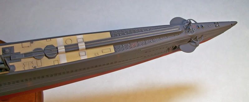
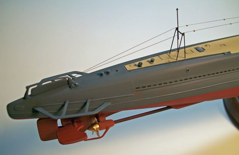
13th and 14th Images: These photos show the front and rear sections after all of the weathering was done. Medium gray pastel powder was applied to the entire deck area with a soft bristle brush. The brush was then scrubbed over the deck. Doing this darkened the tan color and made the finish uneven, which it more realistic. Model Master light ghost gray was used to dry-brush all the upper hull sides and gray deck details.
Until next time…
Phillip1


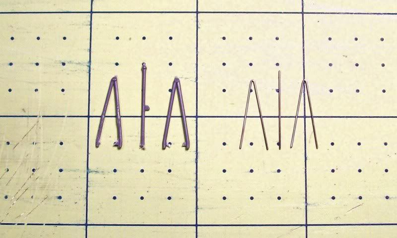
 ;but could any body tell me the working mechanism of her retractable forward planes? Thanks