Hi there Hank, Meister Baumann, Tom, Marijin and all,
Thanks very much for your feedback and your interest, really much appreciated.
BB62vet wrote: I noticed that you have added frames on either side of the inside of the hull - this would be consistent with the boat as shown in your photo #1015, but only partially exposed.
My guess is that the framing was covered by the 1950s, but that's only a guess.
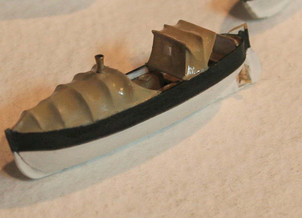
Honestly, I was not able to clarify this subject. It was imposible to find any clear picture of the inside of the inboard details of the whale boat model I was reproducing, and as only source I followed the model of this whale boat:
...along with the sketches of Al Ross in his AOTS The Sullivans --very clear things, on the other hand-- and both seemed to describe the same thing, i.e., frames. Your reasoning sounds consistent, and you are probably right. Too bad, because at this stage of the construction to go back to the beginning, with the stern complete, and everything that should be deleted would be no good. I know myself and my fat fingers too well at this stage of my life.
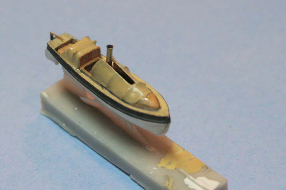
On the other hand, the second picture that you uploaded to the thread has allowed to me to realize that I had omitted the hooks and reinforcements that were used to lift the whaler out of the drink. I have added the elements accordingly, and also some other things that I had not done yet:
With this, there is more detail, and again at no cost in work or time.
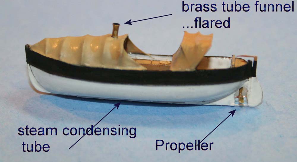
Fliger747 wrote:You might want to check the inclination of the shaft as it is probably not parallel to the keel bottom but inclined as often were the motor assemblies.
Yes, I have noticed that as well. This piece moved during the process, only a fraction of mm., but it did, and was enough to be counted as a mistake. It was the first piece that I set in place in its moment, and it moved probably because of the slit in the hull that it had in the area for the corresponding Revell piece, and that I did not consider necessary to fill. Actually, the skeg broke during the last part of the process, and I had to make a new one, and it was not easy, as it has a curious shape, and is so tiny. As a solution, I will attach the screw with some angle, and as this section of the boat will be inboard-orientated, and behind the davit, I think this obvious mistake will be not noticed.
Fliger747 wrote:I used to run a 26' MWB at one time, as I believe did Hank, but I never paid much attention to the details out of water (half century ago)
My case too, Tom. We had one of these thing on board our ship (39 years ago !!!!), and as it was always hanging from her davits and was rarely used, I had little opportunity (well, and interest) to get inside.
Fliger747 wrote:Just curious as to how you intend to suspend this boat from the davits.
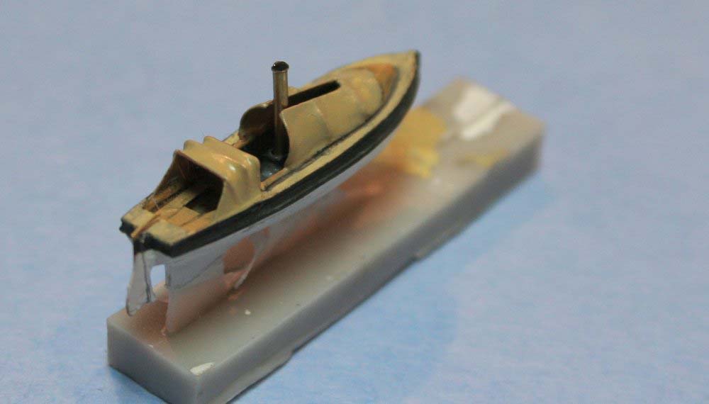
I don�t know myself either, but most surely I will use the plates that are already in place (made with melted plastic, marked with blue arrows), with a sketch of lifting eye, and a block attached to it, to be itself attached to the second block in the top of the davit with sections of stretched sprue. I will try this, but maybe will I have to simplify and omit the lifting eye, as these pieces are very tiny.
Meister Baumann, the Fletchers in the Spanish Navy had no canopy, so it will not be necessary, but your tip is excellent. I have been considering your method for a long time to make the blast bags, using scraps of stretched sprue to make the wrinks covered with white glue. I think it can work wonderfully, and guarantee that they are not similar to each other.
So that�s all for now. Thanks again for your interest, and very best regards from this side of the seas,
Willie.
Amen dico tibi, hodie mecum eris in paradiso (Lk 23,43).
Willie,
Well, I certainly don't intend to make any more work for either of us, but this is one of the problems with modeling items that tend to not have a great deal of reference photos or plans of minute details to rely upon. I think your boat will do fine as it currently exists - your detailing has certainly improved what you began with from the basic kit part.
Hank
HMS III
Mocksville, NC
BB62 vet 68-69
Builder's yard:
USS STODDARD (DD-566) 66-68 1:144, Various Lg Scale FC Directors Finished:
USS NEW JERSEY (BB-62) 67-69 1:200
USN Sloop/Ship PEACOCK (1813) 1:48
ROYAL CAROLINE (1748) 1:47
AVS (1768) 1:48
It has been quite a long time without any update in this thread. I have to say that 1/1 scale life has once more seriously interfered with advanced modelling. Other than this I have been stack with the main mast, virtually the only major element that has to be completed yet.
I have devoted lots of time to the two radar aerials, with less-than-promising results as for now, and at this 1/144 scale, PE seems to not even exist. Too bad.
The second thing to be solved is the wiring up the mast. It is complicated, to say the least. Lots of time were devoted to this subject too, and it was not until a short time ago that I found what I think that can be if the solution, at least something that can be tested.
Before anything else, I added some elements to the hull, the water canals all along the hull, small things that are very easy to build and that add realism when put together. I used for this 0.5x0.4 mm. Evergreen strip. I tried 0.25x0.5 mm. at first, but it was too thing, it could break easily, and this monster hull will require lots of handling yet.
The stern had the very same solution :
And the same all along the hull. I found a couple of interesting details that I gladly added too:
In the last picture it is easy to see the bumps that I made in the hull to give it some uniformity with the oil canning for and aft.
After this, the mast. This pic is an example of what has to be done. Lots of small elements, interfering with each other everywhere, what means that every step has to be carefully calculated:
I decided that the elements have to be built from the inside to the outside, leaving the bigger elements as the last step, and always leaving some room for the secondary wiring lines. The first thing were then the brackets that seem to support the brunt of the weight of the wiring lines. In my files, I could find 14 of these brackets, most of the placed at uneven distances:
This is USS Isherwood, but after everything I have reseached, this mast is representative of any square-bridged Fletcher. From the flying bridge downwards there are some more. I made four, the last one being necessary to secure the lower section of the wiring, but only three of the will be visible in my model, as the rest of them would be covered by the deck of the commodore cabin the this ship displayed.
As it can be observed, the brackets are made fast on the sides. I made the circles with 4.0 mm Evergreen tubing, filed and sanded inside and outside to acceptable calibers, cut in the rear to allow the correct placing, and completed with scraps of stretched sprue. In this case, I had to trade reality against realism, beause I was not able to handle smaller pieces. This is the main mast as for now :
I know they are a bit too thick, but I think this problem can be covered to some extent by not giving them any kind of shading when they are painted, and only some dry-brush lights, so that they are apparent but without highlighting their true thickness.
I hope you like the process, and very best regards from this side,
Willie.
Amen dico tibi, hodie mecum eris in paradiso (Lk 23,43).
marijn van gils wrote:Great to see you back at the bench Willie!
Thanks very much for your welcome. Actually I was never away from the bench --I simply changed the corner. When the work on the radars and the wiring became too frustrating and unsucessful, I devoted some time and research to German U-Boote artillery. German U-Boote in WWII are my subject since I was a teenager, and I have already in store three Revell submarines in 1/72 scale, a VII-C (for U201, Adalbert Schnee), an early IX-C (for U66, Richard Zapp) and a late war IX-C with extended Wintergarten (for U516, Hans-Rutgen Tillessen).
For these monsters (in 1/72 they are huge !!!) I have already made all the artillery but the Flak Vierling for the late war IX-C, what means two 105 mm, one 88 mm., two single and two double 20 mm. mounts and two 37 mm. single mounts. This time I had some more success than with the Jorge Juan main mast.
The 20 mm. Flaks needed lots of scratch build, but I think they came out quite nicely :
As for the 37 mm. Flaks, only one was necessary, but this mount has been my favourite naval gun ever, since I discovered this picture in the summer 1980, virtually a lifetime ago:
The caption said briefly "U505, the first German submarine to surrender to the US Navy". It was only much time later that I discovered that this is not U505 at all, but U172, and that she was not surrendering, but just the opposite: she was just coming back to Lorient from the Western Atlantic, with car tires (hanging on the 105 mm. gun, before the bridge) and the flag of US merchant SS Santa Rita as trophies. What a difference.
Anyhow, and for whatever reason, this gun pointing up made me daydream for years and decades. As I had some spares from shared sprues in both IX-C�s, I was able to make two separate models of this Flak gun, one in travelling position and the second one pointing upwards with maximum elevation:
All the rest of the guns are also finished and ready to paint. Sadly my battery charger is dead, and I cannot make any pictures for the moment.
But these U-Boote will have to wait until Jorge Juan is finished. Otherwise I will have too many things to handle at the same time.
So sorry to include this off-topic in the thread, but it has also been a pleasure to share this work with you all.
Very best regards from this corner of the North Atlantic,
Willie.
Amen dico tibi, hodie mecum eris in paradiso (Lk 23,43).
I just sent you a PM re. our email exchanges (or lack thereof!!). Your work on the mast/RADARs and the small deck guns looks 1st Class - I hope to get back to lil STOD soon enough - I'm about at the same area (main mast) as you seem to be. Glad to see new posts from you and your progress!!
Hank
HMS III
Mocksville, NC
BB62 vet 68-69
Builder's yard:
USS STODDARD (DD-566) 66-68 1:144, Various Lg Scale FC Directors Finished:
USS NEW JERSEY (BB-62) 67-69 1:200
USN Sloop/Ship PEACOCK (1813) 1:48
ROYAL CAROLINE (1748) 1:47
AVS (1768) 1:48
The next step, the torpedo crane, was again a passtime in between I decide on the main mast.
This torpedo crane was quite distinctive in the Fletcher�s silhouette:
It was present in Jorge Juan as well, as it can be seen in this otherwise blurry picture :
After the many pictures I have found of this crane, I could see that there are many different models, or variations, of the same elements, but this one seems to be the most universal, but again with the handle at front or at the side of the main support:
On the other hand, the head of the crane seems to follow the same pattern in all cases, with the same elements in the same position:
The kit offers a crane, but very crude for this scale.
The measures are basically right, and I considered recovering the cross, but I decided that it would take as much time --if not more-- as building a new one, that was what I eventually made. The base is a piece of 2.5 mm. Evergreen rod, with all the rest of the elements built accordingly to this size
When set in place, the mount is quite convincing, and it will be more when it is painted, dry-brushed and finished with a piece of chain hanging. I could not find a clear picture of the base on deck, so I imagined one, and made the body of the crane longer than necessary so that it can be hoisted if desired
I hope you like it, and very best regards from this side,
Willie.
Last edited by Willie on Sat Feb 07, 2026 4:45 pm, edited 1 time in total.
Amen dico tibi, hodie mecum eris in paradiso (Lk 23,43).
JIM BAUMANN wrote:Beautifully made... the sharpness of your styrene work is inspirationa l!
Thanks very much for your remark. It was very easy to make.
The next step, the wiring, was not that easy at all. First, what had to be done is 4 sections of brackets, at an uneven spacing, and lots of wiring in the racks. After some research, I could not find a complete picture of the rear of the main mast of a modernized Fletcher (to say nothing of Jorge Juan herself), and even in sections, I found out that not all the ships had --as usual-- the same arrangements, but I could more or less stablish that most of the ships had similar numbers of brackets in similar sections, so as representative of the class I was using the mast of USS The Sullivans, of which I have excellent pictures.
At first I tried to replicate the racks in the aft stack, and made all the pieces accordingly, using 2.00x0.5 mm. Evergreen strip,with sections of 0.5x0.25 mm. Evergreen as well. It had worked well on the stack, but (I noticed it too late), because it had required no handling at all and I was using small sections of stretched sprue for the wiring itself. It was not the case here: I had to handle it continuously, using copper wire for the wiring, because the stretched sprue broke easily with so much handling and bending at odd angles. I also discovered at my own expense that the copper wire has a life of itself and takes its own decisions, that in even in small bundles can coincide or not with my own decisions.
All this together along with the amount of glue that I had to use made the vertical strips too soft, and eventually they bent and broke. A full three-day work directly to the bin...
I had to start everything again, this time trying to make the thing a bit more solid, using 2.mm Evergreen channel and 0.5x0.5 mm. strip instead. The only drawback is that the channel limits the number of wires to only 5 instead of the 7 that I was using before, but it was now way stronger, and I thought it could cope with the unavoidable handling. It did..
The trickiest thing was to comb the copper wire in the right places at the right angles to form the three waves that are so typical of these masts, and all of them at the same time, the only possible way that I found to have all of them identical. I did the job using a 3.2 mm. tubing section bent under the pressure of two 2.00 mm. rod sections. I made a couple of tests before, and apparently it worked.
I made the middle wave first, and then the third and then the first, because the middle can be done stretching the wires un and down, but the other two have to be made with only a two mm. margin. I said apparently, because this time the copper wires got really temperamental and all the three curves seemed to agree on bending together to almost 30� to the right. It cost me blood to take them to the right position, but more or less I think I got it.
After this I simply had to add stretched sprue sections to the sides of the racks, this time a bit thinner to compensate the thickness of the 0.5 mm. bars.
I had to accept some compromise in the relative thickness of the elements, but I broke nothing, all the elements are there, the racks are not thicker than the mast itself (my fear nr. one) and I have to add the vertical ladder, many smaller elements and all the rigging and halyards yet, so I think the final effect will be good all the same.
Feel free as usual to let me know your views and suggestions if there is something else I can do at this stage.
Very best regards from this side of the ocean,
Willie.
Amen dico tibi, hodie mecum eris in paradiso (Lk 23,43).
And before anything else, thank you gentlemen for your always kind remarks.
As you know, our common friend Hank Strub and I are building the same kind square-bridged Fletcher destroyer, and he has developed some printed parts for his model that are common to all destroyers of this era, and hence for my ship as well.
I prefer to scratch-build before any other option, so in the last months I was making some tests on the radars, but with very little success, and then, after swallowing my pride (an always wise decision many times) I sent an SOS to him, and he graciously replied with a set of radars that he had in store as surplus of his own construction.
This is the first time that I have such a thing in my hands, but IMO to say that they are good is to say very little of them. The quality that he has achieved is more than remarkable. I have been studying them for some hours. The details are as fine and delicate as can be and I can see very little else that could be done. It took me sometime to detach them from the supports, but I was able to do it without breaking anything. Here they are :
They are years light ahead of any of my attempts, and even in a dry fit, they cover he gap in the best possible way:
When they are completely finished and painted, they will look splendid.
So Hank, thanks a million once more for your precious help, and best regards to all of you from this side,
Willie.
Amen dico tibi, hodie mecum eris in paradiso (Lk 23,43).
Well, I'm certainly glad that they:
1) Arrived safe & sound and you were able to remove them from their supports - certainly a job in itself!
2) That they met your expectations and will work out well for your model.
I'm about at the same place with STODDARD in working on the main mast & RADARs. So, after checking out your preceding posts regarding the electrical cables running down the main leg of the mast, I think your approach and work is 1st Class!! I guess some minds think alike in that I've been searching my "stuff" for similar old Bell Telephone wiring which is just like what you've used on your model. I may have to reach out to one of my friends nearby who is into electronics, etc. and see if he has about 12" of that wiring that he could part with.
Once again, you're doing great work here - wonderful to see the progress!!!
Hank
HMS III
Mocksville, NC
BB62 vet 68-69
Builder's yard:
USS STODDARD (DD-566) 66-68 1:144, Various Lg Scale FC Directors Finished:
USS NEW JERSEY (BB-62) 67-69 1:200
USN Sloop/Ship PEACOCK (1813) 1:48
ROYAL CAROLINE (1748) 1:47
AVS (1768) 1:48
After reading your post in the main forum reg. 3D printing, two question comes inmediately to my mind --and please excuse my ignorance:
(1) Are your radars already cured, and I can paint them directly, or should I take some other action before ?
(2) Could I use Humbrol enamel paint ?
At this stage, I would hate to ruin them out of sheer ignorance.
TIA, and very best regards from the North Atlantic,
Willie.
Amen dico tibi, hodie mecum eris in paradiso (Lk 23,43).
Yes! - those parts are already cured. They are ready for painting. As for painting, I can't address Humbrol paints as I don't use them. However, if you have not thrown out the support bases, you could try painting those as an experiment and see how the paint works on them before painting the actual RADAR parts. I use Mr. Color Spray and bottle paint as well as some of the Testors Model Master spray & bottle enamels, so I would think that your paint should work ok. I know that others prime their parts, but as my primer spray paint IS my final paint color, I only use the gray primer when painting. Since these parts are normally (USN) flat black, I also just spray them black and again, no primer. The choice is up to you!
As others have commented on other threads regarding 3D resin parts and painting, acrylics seem to be the preferred type of paint. I guess it's an individual choice; I never found them to work well with the older (Shapeways) type of plastic. The parts I sent you are printed with Phrozen Rapid Black Water Soluble resin and seem to work well with lacquers and enamels. Again, I don't use acrylics so I can't make a comment on whether that will work or not.
Hope this helps,
Hank
HMS III
Mocksville, NC
BB62 vet 68-69
Builder's yard:
USS STODDARD (DD-566) 66-68 1:144, Various Lg Scale FC Directors Finished:
USS NEW JERSEY (BB-62) 67-69 1:200
USN Sloop/Ship PEACOCK (1813) 1:48
ROYAL CAROLINE (1748) 1:47
AVS (1768) 1:48
Even if there were the usual variations in the location of the different elements, the Fletcher class had a common equipment reg. the topgallant masts, and USS McGowan had the most usual location of aerials, this one, in 1956, short time before the transfer to the Spanish Navy, and one that she kept for some years:
The wiring was attached to the masts following also a common pattern, with beautiful curves that were IMO as specifically designed for modelling:
On the other hand, Jorge Juan had an further upper topgallant added AFAIK in the mid 60�s, the moment in which I try to represent her (no other reason than I was born in 1964). Sadly, there is (or I have not been able to find it at least) absolutely no clear picture of this part in both Jorge Juan and sister ship Alcal� Galiano. I have been able to find only these two crops :
One of the elements is clearly an anemometer, very easy to carve in a piece of sprue. The other elements seem to be the AS-390/SRC aerial, two supports for the topgallant mast placed in a 45� angle, and apparently a small rounded platform for two more aerials (?) just under the anemometer.
I am not completely sure that all this is 100% true but I have found no better source, so this will have to do. Making it all was much easier than finding the information.
I think it is quite consistent with the pictures, and in any case it is not unrealistic, and it is enough.
I hope you like it, and very best regards from this side of the seas,
Willie.
Amen dico tibi, hodie mecum eris in paradiso (Lk 23,43).
After further interference of 1/1 life and work, I have gathered some time to give a push to this construction, main mast again, which is the last big element remaining.
After the nightmare of the cable racks, the rest of the elements should be relatively easy to make, and hence, I went further on with the vertical ladder, before the second cable trunk. These vertical ladders were all fixed in the same way, using plain horizontal bars attached to the bulkheads, masts or whatever was necessary. In the case of the main mast attached to the numerous rings available.
The vertical ladder of the main mast in Jorge Juan was fixed with 8 of these sets of bars. The real problem was to get them all in a straight line, as they are in a very visible location, and a deviation from this line, even if minor, would ruin the visual effect. I solved the problem making small elements with 2 mm. Evergreen channel, with the bars attached on both sides. This will allow to make a channel to run the ladder up and down and lake sure the line is straight.
The effect is quite real, as the channel is be disguised by the ladder itself. I completed the set with two sections os PE ladder that I had around.
And over to the next post.
Best regards,
Willie.
Amen dico tibi, hodie mecum eris in paradiso (Lk 23,43).
The second cable trunk, that runs up all the lenght of the main leg, was attached to the mast by means of brackets fore and aft, and was made of different sections screwed together. It would very simple to make if it was not for the fact that it has to go around the platform of the AN/SPS main radar, in order to avoid the scuttle for the vertical ladder.
This is the trunk:
And this was the next headache:
I used a 0.5x2.00 mm. Evergreen stripe. I made the big angle at the top heating the bar, instead of cutting and glueing two sections, to give it some additional strength, and cut the rest of the elements accordingly. It was a headache to make everything dry-fit in position all along the process. I wanted to have this trunk complete, instead of making the sections and glueing them in place, so that I could be able to control the proportions at all times, and complete the small details without making a poly mess.
After much essay and mistake, and some reasonable amount of cursing, I completed the thing with small sections of stretched sprue, and eventually I was able to produce this, 37 pieces all together:
When set in place there are no gaps in the sections, it is parallel to the mast, it has the correct angle to follow the inclination of the platform, it is correctly aligned with the axis, and this is everything I wanted to see.
After this, I finished the small details with stretched sprue again and scraps of 0.4x0.75 mm. Evergreen stripe, added another trunk using 0.5x0.5 mm. Evergereen bar, and the thing was done.
When placed on deck, the effect is quite convincing:
So, I hope you like it, and very best regards from the north Atlantic shores,
Willie.
Amen dico tibi, hodie mecum eris in paradiso (Lk 23,43).